warning light INFINITI Q50 2014 Infiniti Intouch
[x] Cancel search | Manufacturer: INFINITI, Model Year: 2014, Model line: Q50, Model: INFINITI Q50 2014Pages: 274, PDF Size: 1.43 MB
Page 7 of 274
1. Introduction
1-4
LASER PRODUCT
This Infiniti InTouch is certified as a Class 1
laser product.
Infiniti InTouch complies with DHHS Rules
21 CFR Chapter 1, Subchapter J.
WARNING!
.Do not disassemble or modify this
system. There are no user serviceable
parts in Infiniti InTouch.
. If maintenance, adjustments and opera-
tions other than those specified in this
manual are attempted, injury due to laser
radiation and exposure could occur.
TRADEMARKS
HD Radio Technology manufactured under
license from iBiquity Digital Corporation.
U.S. and Foreign Patents. HD Radio
TMand
the HD, HD Radio, and “Arc”logos are
proprietary trademarks of iBiquity Digital
Corp.
SiriusXM services require a subscription
after trial period and are sold separately or
as a package. Our satellite service is
available only to those at least 18 and
older in the 48 contiguous USA and DC. For
more information visit www.siriusxm.com.
“Made for iPod,”“ Made for iPhone,” and
“Made for iPad” mean that an electronic
accessory has been designed to connect
specifically to iPod, iPhone, or iPad,
respectively, and has been certified by
the developer to meet Apple performance
standards. Apple is not responsible for the
operation of this device or its compliance
with safety and regulatory standards.
Please note that the use of this accessory
with iPod, iPhone, or iPad may affect
wireless performance.
Apple, the Apple logo, iPad, iPhone, iPod,
iPod classic, iPod nano, and iPod touch are
trademarks of Apple Inc., registered in the
U.S. and other countries. Lightning is a trademark of Apple Inc. App Store is a
service mark of Apple Inc.
Music recognition technology and related
data are provided by Gracenote®. Grace-
note is the industry standard in music
recognition technology and related content
delivery. For more information visit www.
gracenote.com.
CD and music-related data from Gracenote,
Inc., copyright *
C2000 to present Grace-
note. Gracenote Software, copyright *C
2000 to present Gracenote. One or more
patents owned by Gracenote apply to this
product and service. See the Gracenote
website for a non-exhaustive list of applic-
able Gracenote patents. Gracenote, CDDB,
MusicID, MediaVOCS, the Gracenote logo
and logotype, and the "Powered by Grace-
note" logo are either registered trademarks
or trademarks of Gracenote in the United
States and/or other countries.
Page 41 of 274
3. Heater and air conditioner
3-10
.Any liquid spilled on the heated seat
should be removed immediately with a
dry cloth.
. When cleaning the seat, never use gaso-
line, thinner, or any similar materials.
. If any malfunctions are found or the
heated seat does not operate, turn the
switch off and have the system checked
by an INFINITI retailer.
The front seats are warmed by built-in
heaters. The seat heating system of driver’s
seat and front passenger seat can be
operated independently.
Operation with buttons:
Each time <
>is pushed, the seat heating
mode will change in the following order.
AUTO ?High ?Medium ?Low ?OFF
When seat heating system is activated, the
indicator light on <
>will illuminate. Operation with touch screen:
Touch [
] on the lower display and select
an item from [AUTO], [High], [Medium],
[Low] or [OFF].
AUTO mode setting:
When in the AUTO mode, the seat heating
will turn on/off automatically according to
the conditions such as the temperature
inside the vehicle compartment. Depend-
ing on the conditions, the seat heating will
not turn on even if AUTO is selected. The
settings for the seat heating AUTO mode
can be changed.
“Heater and air conditioner settings”
(page 3-11)
HEATED STEERING-WHEEL (if so
equipped)
WARNING!
Do not use or allow occupants to come into
contact with the heated steering-wheel if you
or the occupants cannot monitor elevated
steering-wheel temperatures or have an
inability to feel pain in those body parts in
contact. Use of the heated steering-wheel by
such people could result in serious injuries.
CAUTION!
. The battery could run down if the
steering-wheel heater is operated while
the engine or the hybrid system is not
running.
. Do not use the steering-wheel heater for
extended periods of time as it may cause
burns and overheating.
. Any liquid spilled on the steering-wheel
should be removed immediately with a
dry cloth.
. When cleaning the steering-wheel, never
use gasoline, thinner, or any similar
Page 106 of 274
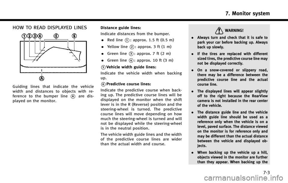
HOW TO READ DISPLAYED LINES
Guiding lines that indicate the vehicle
width and distances to objects with re-
ference to the bumper line
*Aare dis-
played on the monitor. Distance guide lines:
Indicate distances from the bumper.
. Red line
*1: approx. 1.5 ft (0.5 m)
. Yellow line
*2: approx. 3 ft (1 m)
. Green line
*3: approx. 7 ft (2 m)
. Green line
*4: approx. 10 ft (3 m)
*5Vehicle width guide lines:
Indicate the vehicle width when backing
up.
*6Predictive course lines:
Indicate the predictive course when back-
ing up. The predictive course lines will be
displayed on the monitor when the shift
lever is in the R (Reverse) position and the
steering-wheel is turned. The predictive
course lines will move depending on how
much the steering-wheel is turned and will
not be displayed while the steering-wheel
is in the neutral position.
The vehicle width guide lines and the width
of the predictive course lines are wider
than the actual width and course.
WARNING!
. Always turn and check that it is safe to
park your car before backing up. Always
back up slowly.
. If the tires are replaced with different
sized tires, the predictive course line may
not be displayed correctly.
. On a snow-covered or slippery road,
there may be a difference between the
predictive course line and the actual
course line.
. The displayed lines will appear slightly
off to the right because the RearView
camera is not installed in the rear center
of the vehicle.
. The distance guide line and the vehicle
width guide line should be used as a
reference only when the vehicle is on a
level, paved surface. The distance viewed
on the monitor is for reference only and
may be different than the actual distance
between the vehicle and displayed ob-
jects.
. When backing up the vehicle up a hill,
objects viewed in the monitor are further
than they appear. When backing up the
7. Monitor system
7-3
Page 113 of 274
7. Monitor system
7-10
INFO:
When the monitor displays the front view and
the steering-wheel turns about 90 degrees or
less from the neutral position, both the right
and left predictive course lines
*6are dis-
played. When the steering-wheel turns about 90
degrees or more, a line is displayed only on the
opposite side of the turn.
Bird-eye view
WARNING!
. Objects in the bird-eye view will appear
further than the actual distance because
the bird-eye view is a pseudo view that is
processed by combining the views from
the cameras on the outside mirrors, the
front and the rear of the vehicle.
. Tall objects, such as a curb or vehicle,
may be misaligned or not displayed at
the seam of the views.
. Objects that are above the camera cannot
be displayed.
. The view for the bird-eye view may be
misaligned when the camera position
alters. .
A line on the ground may be misaligned
and is not seen as being straight at the
seam of the views. The misalignment will
increase as the line proceeds away from
the vehicle.
. The tire angle display does not indicate
the actual tire angle
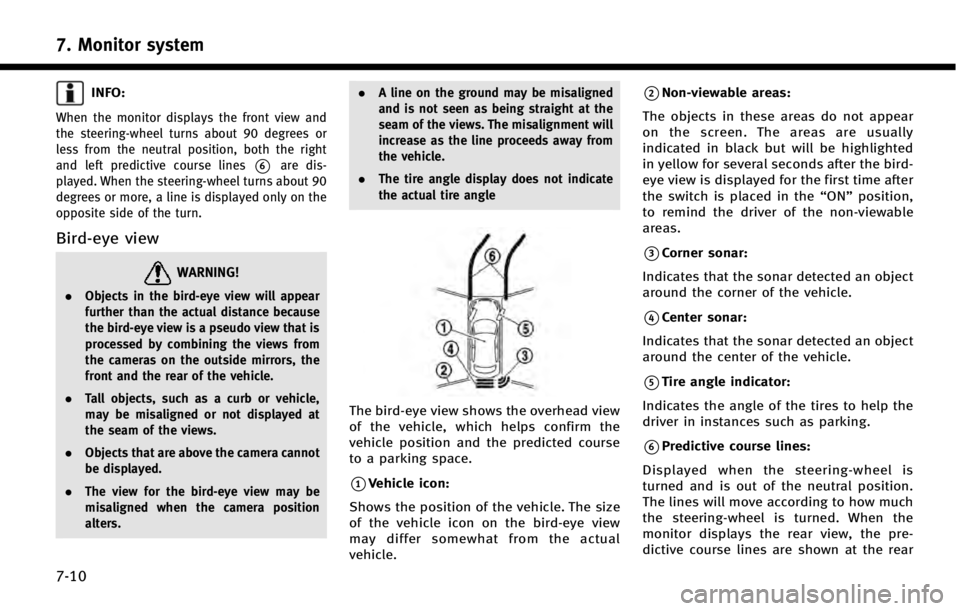
The bird-eye view shows the overhead view
of the vehicle, which helps confirm the
vehicle position and the predicted course
to a parking space.
*1Vehicle icon:
Shows the position of the vehicle. The size
of the vehicle icon on the bird-eye view
may differ somewhat from the actual
vehicle.
*2Non-viewable areas:
The objects in these areas do not appear
on the screen. The areas are usually
indicated in black but will be highlighted
in yellow for several seconds after the bird-
eye view is displayed for the first time after
the switch is placed in the “ON”position,
to remind the driver of the non-viewable
areas.
*3Corner sonar:
Indicates that the sonar detected an object
around the corner of the vehicle.
*4Center sonar:
Indicates that the sonar detected an object
around the center of the vehicle.
*5Tire angle indicator:
Indicates the angle of the tires to help the
driver in instances such as parking.
*6Predictive course lines:
Displayed when the steering-wheel is
turned and is out of the neutral position.
The lines will move according to how much
the steering-wheel is turned. When the
monitor displays the rear view, the pre-
dictive course lines are shown at the rear
Page 116 of 274

6 MPH (10 km/h). It is reactivated at lower
speeds.
Warning tone and indicator
As the vehicle approaches the detected
objects, the color of the warning indicator
and the tone will change from green to
yellow and then to red.
IndicatorTone
green
(blink slow) intermittent (slow)
yellow
(blink fast) intermittent (fast)
red
(no blinking) continuous
The intermittent tone will stop after three
seconds when an object is detected by
only the corner sonar and the distance
does not change.
The tone will stop when the object is away
from the vehicle.
Turning sonar system on/off
When the Sonar·MOD key is touched, the
indicator light on the key will turn off and
the sonar will turn off temporarily. The
Moving Object Detection (MOD) system will
also be turned off at the same time.
“Moving Object Detection (MOD)”
(page 7-13)
When the switch is touched again, the
indicator light will illuminate and the sonar
will turn back on.
In the cases below, the sonar will be turned
back on automatically: . When the shift lever is in the R
(Reverse) position.
. When
screen other than the camera view is
shown on the display.
. When the vehicle speed decreases
below approximately 6 MPH (10 km/h).
. When the ignition switch is placed in
the “OFF” position and turned back to
the “ON” position again.
. When the switch is selected, the MOD
function will also be turned off.
To prevent the sonar system from activat- ing altogether, change the status the
camera settings menu.
“Around View Monitor settings”
(page 7-16)
INFO:
Touching the sonar switch will also turn on/off
the sonar system temporarily.
MOVING OBJECT DETECTION (MOD)
The Moving Object Detection (MOD) system
informs the driver of any moving objects
surrounding the vehicle with images and a
chime when driving out of garages, man-
euvering into parking lots and in other
such instances.
The MOD system operates in the following
conditions when the camera view is
displayed:
. When the shift lever is in the P (Park) or
N (Neutral) position and the vehicle is
stopped, the MOD system detects the
moving objects in the bird-eye view.
The MOD system will not operate if the
outside mirror is moving in or out or if
either door is opened.
. When the shift lever is in the D (Drive)
position and the vehicle speed is below
7. Monitor system
7-13
Page 117 of 274
7. Monitor system
7-14
approximately 5 MPH (8 km/h), the
MOD system detects moving objects in
the front view or front-wide view.
. When the shift lever is in the R
(Reverse) position and the vehicle
speed is below approximately 5 MPH
(8 km/h), the MOD system detects
moving objects in the rear view or
rear-wide view. The MOD system will
not operate if the trunk lid is open.
INFO:
.
The MOD system does not detect moving
objects in the front-side view. The MOD
indicator is not displayed on the screen
when in this view.
.While the sonar/BCI warning tone is beep-
ing, the MOD system does not chime.
WARNING!
. The MOD system is not a substitute for
proper vehicle operation and is not
designed to prevent contact with the
objects surrounding the vehicle. When
maneuvering, always use the outside
mirror and rearview mirror and turn and
check the surrounding area to ensure it is safe to maneuver.
. The MOD system does not have the
function to detect the surrounding sta-
tionary objects.
. Do not use the MOD system when towing
a trailer. The system may not function
properly.
. Excessive noise (for example, audio
system volume or open vehicle window)
will interfere with the chime sound, and
it may not be heard.
. The MOD system performance will be
limited according to environmental con-
ditions and surrounding objects such as:
— When there is low contrast between
background and the moving objects.
— When there is a blinking source of
light.
— When strong light such as another
vehicle’s headlight or sunlight is pre-
sent.
— When camera orientation is not in its
usual position, such as when a mirror
is folded.
— When there is dirt, water drops or
snow on the camera lens. —
When the position of the moving
objects in the display is not changed.
. The MOD system might detect something
like flowing water droplets on the camera
lens, white smoke from the muffler,
moving shadows, etc.
. The MOD system may not function
properly depending on the speed, direc-
tion, distance or shape of the moving
objects.
. If your vehicle sustains damage to the
parts where the camera is installed,
leaving it misaligned or bent, the sensing
zone may be altered and the MOD system
may not detect objects properly.
Page 119 of 274
![INFINITI Q50 2014 Infiniti Intouch 7. Monitor system
7-16
AROUND VIEW MONITOR SETTINGS
Around View Monitor settings can be changed with the following procedure.
1. Push<MENU>.
2. Touch [Settings].
3. Touch [Camera/Sonar].
Available set INFINITI Q50 2014 Infiniti Intouch 7. Monitor system
7-16
AROUND VIEW MONITOR SETTINGS
Around View Monitor settings can be changed with the following procedure.
1. Push<MENU>.
2. Touch [Settings].
3. Touch [Camera/Sonar].
Available set](/img/42/34966/w960_34966-118.png)
7. Monitor system
7-16
AROUND VIEW MONITOR SETTINGS
Around View Monitor settings can be changed with the following procedure.
1. Push