torque INFINITI QX4 2001 Factory Service Manual
[x] Cancel search | Manufacturer: INFINITI, Model Year: 2001, Model line: QX4, Model: INFINITI QX4 2001Pages: 2395, PDF Size: 43.2 MB
Page 1745 of 2395

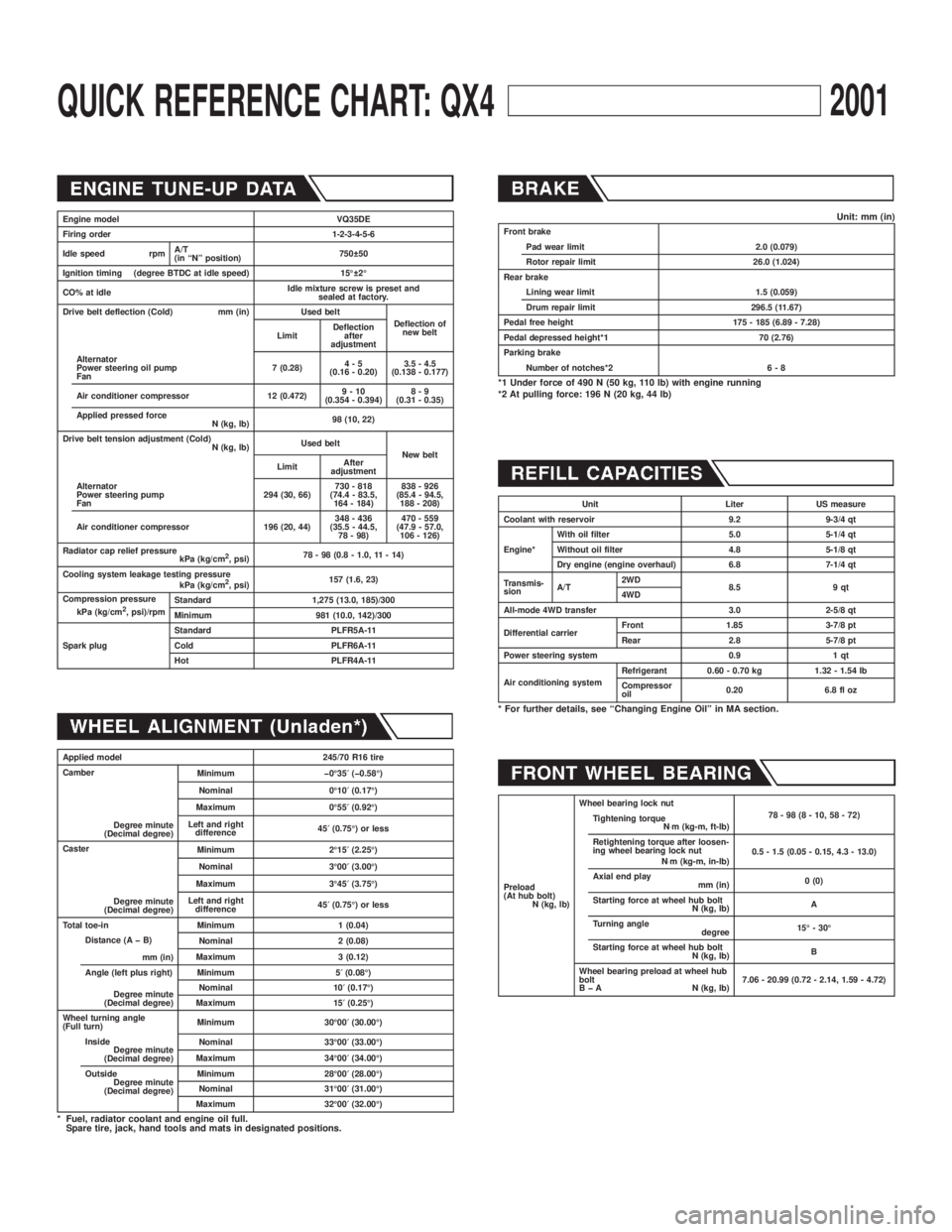
QUICK REFERENCE CHART: QX42001
Engine model VQ35DE
Firing order 1-2-3-4-5-6
Idle speed rpmA/T
(in ªNº position)750 50
Ignition timing (degree BTDC at idle speed) 15É 2É
CO% at idleIdle mixture screw is preset and
sealed at factory.
Drive belt deflection (Cold) mm (in) Used belt
Deflection of
new belt
LimitDeflection
after
adjustment
Alternator
Power steering oil pump
Fan7 (0.28)4-5
(0.16 - 0.20)3.5 - 4.5
(0.138 - 0.177)
Air conditioner compressor 12 (0.472)9-10
(0.354 - 0.394)8-9
(0.31 - 0.35)
Applied pressed force
N (kg, lb)98 (10, 22)
Drive belt tension adjustment (Cold)
N (kg, lb)Used belt
New belt
LimitAfter
adjustment
Alternator
Power steering pump
Fan294 (30, 66)730 - 818
(74.4 - 83.5,
164 - 184)838 - 926
(85.4 - 94.5,
188 - 208)
Air conditioner compressor 196 (20, 44)348 - 436
(35.5 - 44.5,
78 - 98)470 - 559
(47.9 - 57.0,
106 - 126)
Radiator cap relief pressure
kPa (kg/cm
2, psi)78 - 98 (0.8 - 1.0, 11 - 14)
Cooling system leakage testing pressure
kPa (kg/cm
2, psi)157 (1.6, 23)
Compression pressure
kPa (kg/cm
2, psi)/rpmStandard 1,275 (13.0, 185)/300
Minimum 981 (10.0, 142)/300
Spark plugStandard PLFR5A-11
Cold PLFR6A-11
Hot PLFR4A-11
Applied model 245/70 R16 tire
Camber
Degree minute
(Decimal degree)Minimum þ0É35¢(þ0.58É)
Nominal 0É10¢(0.17É)
Maximum 0É55¢(0.92É)
Left and right
difference45¢(0.75É) or less
Caster
Degree minute
(Decimal degree)Minimum 2É15¢(2.25É)
Nominal 3É00¢(3.00É)
Maximum 3É45¢(3.75É)
Left and right
difference45¢(0.75É) or less
Total toe-in Minimum 1 (0.04)
Distance (A þ B)
mm (in)Nominal 2 (0.08)
Maximum 3 (0.12)
Angle (left plus right)
Degree minute
(Decimal degree)Minimum 5¢(0.08É)
Nominal 10¢(0.17É)
Maximum 15¢(0.25É)
Wheel turning angle
(Full turn)Minimum 30É00¢(30.00É)
Inside
Degree minute
(Decimal degree)Nominal 33É00¢(33.00É)
Maximum 34É00¢(34.00É)
Outside
Degree minute
(Decimal degree)Minimum 28É00¢(28.00É)
Nominal 31É00¢(31.00É)
Maximum 32É00¢(32.00É)
* Fuel, radiator coolant and engine oil full.
Spare tire, jack, hand tools and mats in designated positions.
Unit: mm (in)Front brake
Pad wear limit 2.0 (0.079)
Rotor repair limit 26.0 (1.024)
Rear brake
Lining wear limit 1.5 (0.059)
Drum repair limit 296.5 (11.67)
Pedal free height 175 - 185 (6.89 - 7.28)
Pedal depressed height*1 70 (2.76)
Parking brake
Number of notches*2 6 - 8
*1 Under force of 490 N (50 kg, 110 lb) with engine running
*2 At pulling force: 196 N (20 kg, 44 lb)
Unit Liter US measure
Coolant with reservoir 9.2 9-3/4 qt
Engine*With oil filter 5.0 5-1/4 qt
Without oil filter 4.8 5-1/8 qt
Dry engine (engine overhaul) 6.8 7-1/4 qt
Transmis-
sionA/T2WD
8.5 9 qt
4WD
All-mode 4WD transfer 3.0 2-5/8 qt
Differential carrierFront 1.85 3-7/8 pt
Rear 2.8 5-7/8 pt
Power steering system 0.9 1 qt
Air conditioning systemRefrigerant 0.60 - 0.70 kg 1.32 - 1.54 lb
Compressor
oil0.20 6.8 fl oz
* For further details, see ªChanging Engine Oilº in MA section.
Preload
(At hub bolt)
N (kg, lb)Wheel bearing lock nut
78-98(8-10,58-72)
Tightening torque
N×m (kg-m, ft-lb)
Retightening torque after loosen-
ing wheel bearing lock nut
N×m (kg-m, in-lb)0.5 - 1.5 (0.05 - 0.15, 4.3 - 13.0)
Axial end play
mm (in)0 (0)
Starting force at wheel hub bolt
N (kg, lb)A
Turning angle
degree15É - 30É
Starting force at wheel hub bolt
N (kg, lb)B
Wheel bearing preload at wheel hub
bolt
B þ A N (kg, lb)7.06 - 20.99 (0.72 - 2.14, 1.59 - 4.72)
Page 1747 of 2395

Wheels & Tires ..........................................................44
LIFTING POINTS AND TOW TRUCK TOWING...........45
Screw Jack ................................................................45
Garage Jack and Safety Stand .................................46
2-pole Lift ...................................................................47
Tow Truck Towing ......................................................472WD MODELS.........................................................48
4WD MODELS.........................................................48
VEHICLE RECOVERY..............................................49
TIGHTENING TORQUE OF STANDARD BOLTS........50
SAE J1930 TERMINOLOGY LIST................................51
SAE J1930 Terminology List .....................................51
CONTENTS(Cont'd)
GI-2
Page 1754 of 2395

NBGI0002
IThe captionsWARNINGandCAUTIONwarn you of steps that must be followed to prevent personal injury
and/or damage to some part of the vehicle.
WARNINGindicates the possibility of personal injury if instructions are not followed.
CAUTIONindicates the possibility of component damage if instructions are not followed.
BOLD TYPED STATEMENTSexceptWARNINGandCAUTIONgive you helpful information.
IALPHABETICAL INDEXis provided at the end of this manual so that you can rapidly find the item and
page you are searching for.
IA QUICK REFERENCE INDEX, a black tab (e.g.
) is provided on the first page. You can quickly find
the first page of each section by mating it to the section's black tab.
ITHE CONTENTSare listed on the first page of each section.
ITHE TITLEis indicated on the upper portion of each page and shows the part or system.
ITHE PAGE NUMBERof each section consists of two letters which designate the particular section and a
number (e.g. ªBR-5º).
ITHE LARGE ILLUSTRATIONSare exploded views (See below.) and contain tightening torques, lubrica-
tion points, section number of thePARTS CATALOG(e.g. SEC. 440) and other information necessary to
perform repairs.
The illustrations should be used in reference to service matters only. When ordering parts, refer to the
appropriatePARTS CATALOG.
SBR364AC
ITHE SMALL ILLUSTRATIONSshow the important steps such as inspection, use of special tools, knacks
of work and hidden or tricky steps which are not shown in the previous large illustrations.
Assembly, inspection and adjustment procedures for the complicated units such as the automatic transaxle
or transmission, etc. are presented in a step-by-step format where necessary.
ITheUNITSgiven in this manual are primarily expressed as the SI UNIT (International System of Unit),
and alternatively expressed in the metric system and in the yard/pound system.
ªExampleº
Tightening torque:
59 - 78 N´m (6.0 - 8.0 kg-m, 43 - 58 ft-lb)
ITROUBLE DIAGNOSESare included in sections dealing with complicated components.
MA
EM
LC
EC
FE
AT
TF
PD
AX
SU
BR
ST
RS
BT
HA
SC
EL
IDX
HOW TO USE THIS MANUAL
GI-9
Page 1755 of 2395

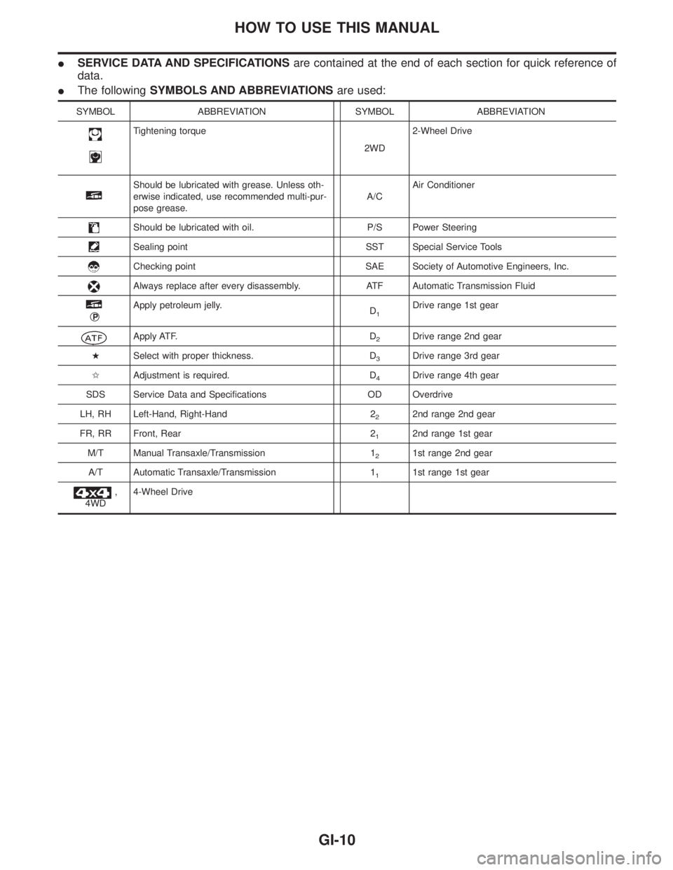
ISERVICE DATA AND SPECIFICATIONSare contained at the end of each section for quick reference of
data.
IThe followingSYMBOLS AND ABBREVIATIONSare used:
SYMBOL ABBREVIATION SYMBOL ABBREVIATION
Tightening torque
2WD2-Wheel Drive
Should be lubricated with grease. Unless oth-
erwise indicated, use recommended multi-pur-
pose grease.A/CAir Conditioner
Should be lubricated with oil. P/S Power Steering
Sealing point SST Special Service Tools
Checking point SAE Society of Automotive Engineers, Inc.
Always replace after every disassembly. ATF Automatic Transmission Fluid
qP
Apply petroleum jelly.
D1Drive range 1st gear
Apply ATF. D2Drive range 2nd gear
HSelect with proper thickness. D
3Drive range 3rd gear
IAdjustment is required. D
4Drive range 4th gear
SDS Service Data and Specifications OD Overdrive
LH, RH Left-Hand, Right-Hand 2
22nd range 2nd gear
FR, RR Front, Rear 2
12nd range 1st gear
M/T Manual Transaxle/Transmission 1
21st range 2nd gear
A/T Automatic Transaxle/Transmission 1
11st range 1st gear
,
4WD4-Wheel Drive
HOW TO USE THIS MANUAL
GI-10
Page 1795 of 2395

NBGI0009
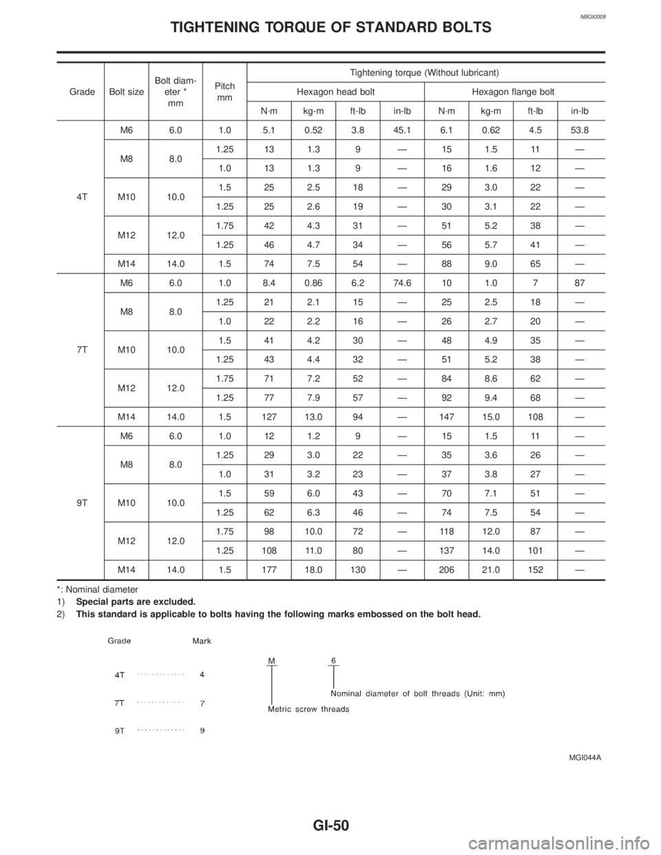
Grade Bolt sizeBolt diam-
eter *
mmPitch
mmTightening torque (Without lubricant)
Hexagon head bolt Hexagon flange bolt
N´m kg-m ft-lb in-lb N´m kg-m ft-lb in-lb
4TM6 6.0 1.0 5.1 0.52 3.8 45.1 6.1 0.62 4.5 53.8
M8 8.01.25 13 1.3 9 Ð 15 1.5 11 Ð
1.0 13 1.3 9 Ð 16 1.6 12 Ð
M10 10.01.5 25 2.5 18 Ð 29 3.0 22 Ð
1.25 25 2.6 19 Ð 30 3.1 22 Ð
M12 12.01.75 42 4.3 31 Ð 51 5.2 38 Ð
1.25 46 4.7 34 Ð 56 5.7 41 Ð
M14 14.0 1.5 74 7.5 54 Ð 88 9.0 65 Ð
7TM6 6.0 1.0 8.4 0.86 6.2 74.6 10 1.0 7 87
M8 8.01.25 21 2.1 15 Ð 25 2.5 18 Ð
1.0 22 2.2 16 Ð 26 2.7 20 Ð
M10 10.01.5 41 4.2 30 Ð 48 4.9 35 Ð
1.25 43 4.4 32 Ð 51 5.2 38 Ð
M12 12.01.75 71 7.2 52 Ð 84 8.6 62 Ð
1.25 77 7.9 57 Ð 92 9.4 68 Ð
M14 14.0 1.5 127 13.0 94 Ð 147 15.0 108 Ð
9TM6 6.0 1.0 12 1.2 9 Ð 15 1.5 11 Ð
M8 8.01.25 29 3.0 22 Ð 35 3.6 26 Ð
1.0 31 3.2 23 Ð 37 3.8 27 Ð
M10 10.01.5 59 6.0 43 Ð 70 7.1 51 Ð
1.25 62 6.3 46 Ð 74 7.5 54 Ð
M12 12.01.75 98 10.0 72 Ð 118 12.0 87 Ð
1.25 108 11.0 80 Ð 137 14.0 101 Ð
M14 14.0 1.5 177 18.0 130 Ð 206 21.0 152 Ð
*: Nominal diameter
1)Special parts are excluded.
2)This standard is applicable to bolts having the following marks embossed on the bolt head.
MGI044A
TIGHTENING TORQUE OF STANDARD BOLTS
GI-50
Page 1799 of 2395

NEW TERMNEW ACRONYM /
ABBREVIATIONOLD TERM
Supercharger bypass SCB ***
System readiness test SRT ***
Thermal vacuum valve TVV Thermal vacuum valve
Three way catalyst TWC Catalyst
Three way catalytic converter system TWC system ***
Three way + oxidation catalyst TWC + OC Catalyst
Three way + oxidation catalytic converter
systemTWC + OC system ***
Throttle body TB Throttle chamber
SPI body
Throttle body fuel injection system TBI system Fuel injection control
Throttle position TP Throttle position
Throttle position sensor TPS Throttle sensor
Throttle position switch TP switch Throttle switch
Torque converter clutch solenoid valve TCC solenoid valve Lock-up cancel solenoid
Lock-up solenoid
Transmission control module TCM A/T control unit
Turbocharger TC Turbocharger
Vehicle speed sensor VSS Vehicle speed sensor
Volume air flow sensor VAFS Air flow meter
Warm up oxidation catalyst WU-OC Catalyst
Warm up oxidation catalytic converter sys-
temWU-OC system ***
Warm up three way catalyst WU-TWC Catalyst
Warm up three way catalytic converter
systemWU-TWC system ***
Wide open throttle position switch WOTP switch Full switch
SAE J1930 TERMINOLOGY LIST
SAE J1930 Terminology List (Cont'd)
GI-54
Page 1805 of 2395

CAUTION:
When replacing or cleaning refrigerant cycle components, observe the following.
IWhen the compressor is removed, store it in the same position as it is when mounted on the car.
Failure to do so will cause lubricant to enter the low pressure chamber.
IWhen connecting tubes, always use a torque wrench and a back-up wrench.
IAfter disconnecting tubes, immediately plug all openings to prevent entry of dirt and moisture.
IWhen installing an air conditioner in the vehicle, connect the pipes as the final stage of the opera-
tion. Do not remove the seal caps of pipes and other components until just before required for
connection.
IAllow components stored in cool areas to warm to working area temperature before removing seal
caps. This prevents condensation from forming inside A/C components.
IThoroughly remove moisture from the refrigeration system before charging the refrigerant.
IAlways replace used O-rings.
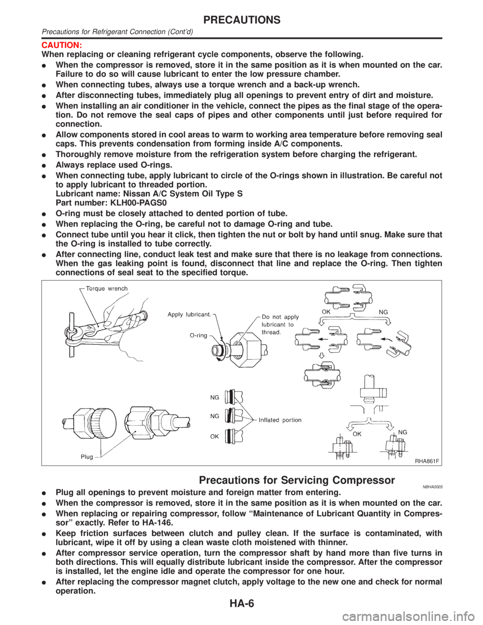
IWhen connecting tube, apply lubricant to circle of the O-rings shown in illustration. Be careful not
to apply lubricant to threaded portion.
Lubricant name: Nissan A/C System Oil Type S
Part number: KLH00-PAGS0
IO-ring must be closely attached to dented portion of tube.
IWhen replacing the O-ring, be careful not to damage O-ring and tube.
IConnect tube until you hear it click, then tighten the nut or bolt by hand until snug. Make sure that
the O-ring is installed to tube correctly.
IAfter connecting line, conduct leak test and make sure that there is no leakage from connections.
When the gas leaking point is found, disconnect that line and replace the O-ring. Then tighten
connections of seal seat to the specified torque.
RHA861F
Precautions for Servicing CompressorNBHA0005IPlug all openings to prevent moisture and foreign matter from entering.
IWhen the compressor is removed, store it in the same position as it is when mounted on the car.
IWhen replacing or repairing compressor, follow ªMaintenance of Lubricant Quantity in Compres-
sorº exactly. Refer to HA-146.
IKeep friction surfaces between clutch and pulley clean. If the surface is contaminated, with
lubricant, wipe it off by using a clean waste cloth moistened with thinner.
IAfter compressor service operation, turn the compressor shaft by hand more than five turns in
both directions. This will equally distribute lubricant inside the compressor. After the compressor
is installed, let the engine idle and operate the compressor for one hour.
IAfter replacing the compressor magnet clutch, apply voltage to the new one and check for normal
operation.
PRECAUTIONS
Precautions for Refrigerant Connection (Cont'd)
HA-6
Page 1947 of 2395

Lubricant Adjusting Procedure for Components
Replacement Except Compressor
=NBHA0071S0201After replacing any of the following major components, add the
correct amount of lubricant to the system.
Amount of lubricant to be added
Part replacedLubricant to be added to
system
Remarks
Amount of lubricant
m(US fl oz, Imp fl oz)
Evaporator 75 (2.5, 2.6) Ð
Condenser 75 (2.5, 2.6) Ð
Liquid tank 5 (0.2, 0.2)Add if compressor is not
replaced. *1
In case of refrigerant
leak30 (1.0, 1.1) Large leak
Ð Small leak *2
*1: If compressor is replaced, addition of lubricant is included in the table.
*2: If refrigerant leak is small, no addition of lubricant is needed.
Lubricant Adjusting Procedure for Compressor
Replacement
NBHA0071S02021. Before connecting ACR4 to vehicle, check ACR4 gauges. No
refrigerant pressure should be displayed. If NG, recover refrig-
erant from equipment lines.
2. Connect ACR4 to vehicle. Confirm refrigerant purity in supply
tank using ACR4 and refrigerant identifier. If NG, refer to
ªCONTAMINATED REFRIGERANTº, HA-2.
3. Confirm refrigerant purity in vehicle A/C system using ACR4
and refrigerant identifier. If NG, refer to ªCONTAMINATED
REFRIGERANTº, HA-2.
4. Discharge refrigerant into the refrigerant recovery/recycling
equipment. Measure lubricant discharged into the recovery/
recycling equipment.
5. Remove the drain plug of the ªoldº (removed) compressor.
Drain the lubricant into a graduated container and record the
amount of drained lubricant.
6. Remove the drain plug and drain the lubricant from the ªnewº
compressor into a separate, clean container.
7. Measure an amount of new lubricant installed equal to amount
drained from ªoldº compressor. Add this lubricant to ªnewº com-
pressor through the suction port opening.
8. Measure an amount of new lubricant equal to the amount
recovered during discharging. Add this lubricant to ªnewº com-
pressor through the suction port opening.
9. Torque the drain plug.
18 - 19 N´m (1.8 - 1.9 kg-m, 13 - 14 ft-lb)
10. If the liquid tank also needs to be replaced, add an additional
5m(0.2 US fl oz, 0.2 Imp fl oz) of lubricant at this time.
Do not add this 5 m(0.2 US fl oz, 0.2 Imp fl oz) of lubri-
cant if only replacing the compressor.
SERVICE PROCEDURE
Maintenance of Lubricant Quantity in Compressor (Cont'd)
HA-148
Page 1951 of 2395

CoilNBHA0075S03Check coil for loose connection or cracked insulation.
RHA142E
INSTALLATIONNBHA0076IInstall the field coil.
Be sure to align the coil's pin with the hole in the com-
pressor's front head.
IInstall the field coil harness clip using a screwdriver.
RHA143EA
IInstall the pulley assembly using the installer and a hand
press, and then install the snap ring using snap ring pliers.
RHA127F
IInstall the clutch disc on the drive shaft, together with the
original shim(s). Press the clutch disc down by hand.
RHA086E
IUsing the holder to prevent clutch disc rotation, tighten the bolt
to 14 N´m (1.4 kg-m, 10 ft-lb) torque.
After tightening the bolt, check that the pulley rotates
smoothly.
SERVICE PROCEDURE
Compressor Clutch (Cont'd)
HA-152
Page 1952 of 2395

RHA087E
ICheck clearance around the entire periphery of clutch disc.
Disc-to-pulley clearance:
0.3 - 0.6 mm (0.012 - 0.024 in)
If the specified clearance is not obtained, replace adjusting
spacer and readjust.
Break-in OperationNBHA0076S01When replacing compressor clutch assembly, always carry out the
break-in operation. This is done by engaging and disengaging the
clutch about thirty times. Break-in operation raises the level of
transmitted torque.
GI
MA
EM
LC
EC
FE
AT
TF
PD
AX
SU
BR
ST
RS
BT
SC
EL
IDX
SERVICE PROCEDURE
Compressor Clutch (Cont'd)
HA-153