torque INFINITI QX4 2001 Factory Owners Manual
[x] Cancel search | Manufacturer: INFINITI, Model Year: 2001, Model line: QX4, Model: INFINITI QX4 2001Pages: 2395, PDF Size: 43.2 MB
Page 1655 of 2395

SEM950F
TIGHTENING PROCEDURESNBEM0006S01Intake ManifoldNBEM0006S0101ITighten in numerical order shown in the figure.
1. Tighten all bolts and nuts to 5 to 10 N´m (0.5 to 1.0 kg-m, 44
to 86 in-lb).
2. Finally tighten all bolts and nuts to 26 to 31 N´m (2.7 to 3.2
kg-m, 20 to 23 ft-lb).
ITighten all bolts and nuts to the final torque, evenly dividing the
tightening into at least five steps.
SEM473G
Fuel TubeNBEM0006S0102ITighten in numerical order shown in the figure.
1. Tighten all bolts to 9.3 to 10.8 N´m (0.95 to 1.1 kg-m, 83 to 95
in-lb).
2. Then tighten all bolts to 21 to 26 N´m (2.1 to 2.7 kg-m, 15 to
20 ft-lb).
SEM474G
Fuel Pressure RegulatorNBEM0006S0103Tighten fuel pressure regulator to 2.9 to 3.8 N´m (0.3 to 0.39 kg-m,
26.0 to 33.9 in-lb).
ITighten screws evenly several times to have the fuel pres-
sure regulator tightened at the specified torque.
IAlways replace O-ring with new ones.
ILubricate O-ring with new engine oil.
SEM475G
Throttle BodyNBEM0006S0105ITighten in numerical order shown in the figure.
1. Tighten all bolts to 8.8 to 10.8 N´m (0.9 to 1.1 kg-m, 79 to 95
in-lb).
2. Then tighten all bolts to 18 to 21 N´m (1.8 to 2.2 kg-m, 13 to
15 ft-lb).
SEM476G
Upper Intake Manifold CollectorNBEM0006S0107Tighten bolts and nuts to 18 to 21 N´m (1.8 to 2.2 kg-m, 13 to 15
ft-lb) in numerical order shown in the figure.
OUTER COMPONENT PARTS
Removal and Installation (Cont'd)
EM-12
Page 1662 of 2395
SEM159F
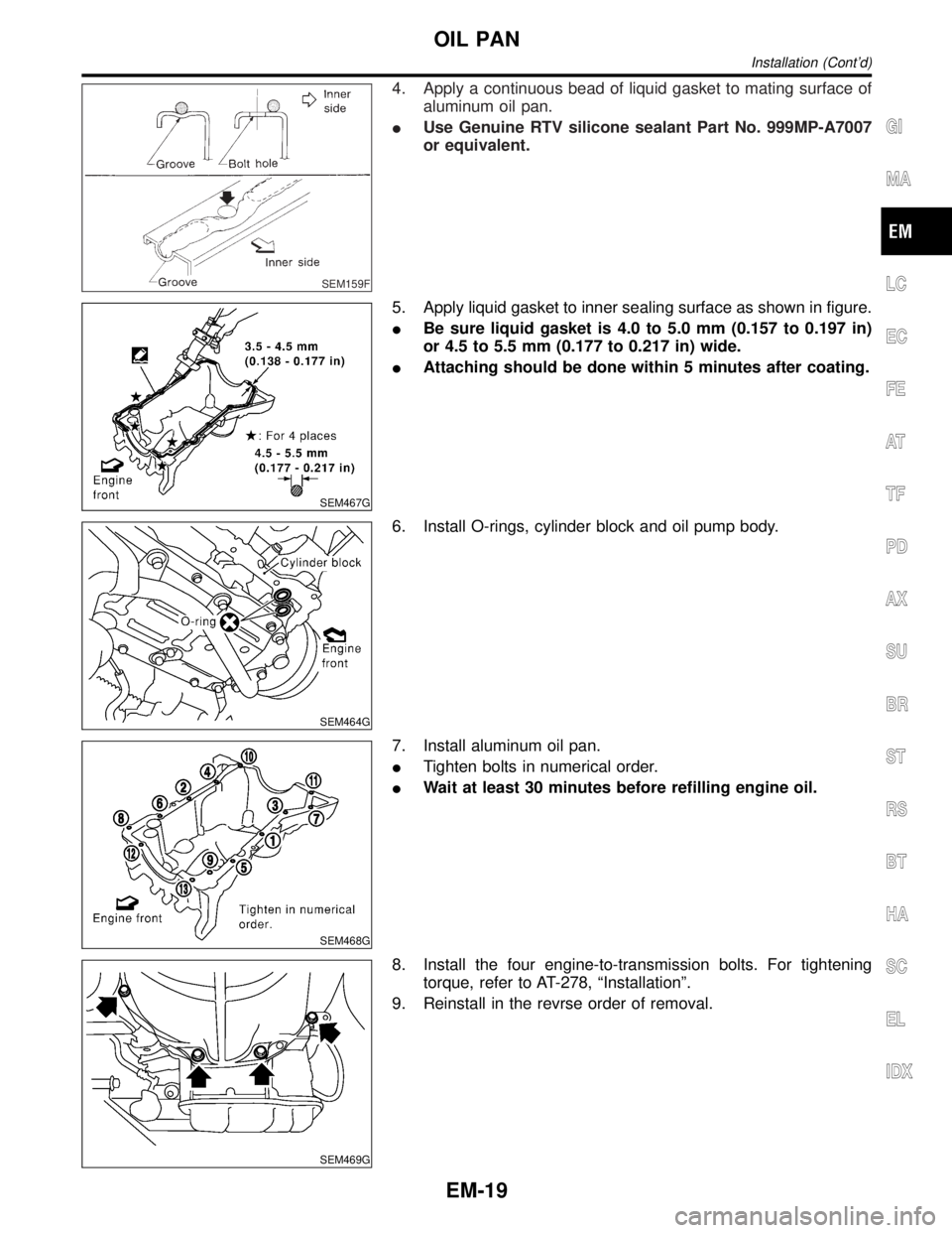
4. Apply a continuous bead of liquid gasket to mating surface of
aluminum oil pan.
IUse Genuine RTV silicone sealant Part No. 999MP-A7007
or equivalent.
SEM467G
5. Apply liquid gasket to inner sealing surface as shown in figure.
IBe sure liquid gasket is 4.0 to 5.0 mm (0.157 to 0.197 in)
or 4.5 to 5.5 mm (0.177 to 0.217 in) wide.
IAttaching should be done within 5 minutes after coating.
SEM464G
6. Install O-rings, cylinder block and oil pump body.
SEM468G
7. Install aluminum oil pan.
ITighten bolts in numerical order.
IWait at least 30 minutes before refilling engine oil.
SEM469G
8. Install the four engine-to-transmission bolts. For tightening
torque, refer to AT-278, ªInstallationº.
9. Reinstall in the revrse order of removal.
GI
MA
LC
EC
FE
AT
TF
PD
AX
SU
BR
ST
RS
BT
HA
SC
EL
IDX
OIL PAN
Installation (Cont'd)
EM-19
Page 1675 of 2395

SEM435G
12. Install O-rings on rear timing chain case.
13. Apply liquid gasket to front timing chain case.
IRefer to ªPOSITION FOR APPLYING LIQUID GASKETº,
EM-21.
IBefore installation, wipe off the protruding sealant.
SEM436G
14. Install rear case pin into dowel pin hole on front timing chain
case.
15. Tighten bolts to the specified torque in order shown in the fig-
ure.
ILeave the bolts unattended for 30 minutes or more after
tightening.
SEM437G
16. Install CVTC cover.
a. Install O-rings at front timing chain case.
b. Install seal ring at CVTC covers.
c. Apply liquid gasket to CVTC covers.
Use genuine RTV silicone sealant Part No. 999MP-A7007 or
equivalent.
IBeing careful not to move the seal ring from the installation
groove, align the dowel pins on the chain case with the holes
to install the CVTC cover.
SEM438G
ITighten in numerical order as shown in the figure.
TIMING CHAIN
Installation (Cont'd)
EM-32
Page 1685 of 2395

SEM861E
InspectionNBEM0019CYLINDER HEAD DISTORTIONNBEM0019S01Clean surface of cylinder head.
Use a reliable straightedge and feeler gauge to check the flatness
of cylinder head surface.
Check along six positions shown in the figure.
Head surface flatness: Limit 0.1 mm (0.004 in)
If beyond the specified limit, resurface or replace it.
The limit for cylinder head resurfacing is determined by the
cylinder block resurfacing.
Resurfacing limit:
Amount of cylinder head resurfacing is ªAº.
Amount of cylinder block resurfacing is ªBº.
The maximum limit : A+ B = 0.2 mm (0.008 in)
After resurfacing cylinder head, check that camshaft rotates freely
by hand. If resistance is felt, cylinder head must be replaced.
Nominal cylinder head height:
126.3 - 126.5 mm (4.972 - 4.980 in)
SEM191F
CAMSHAFT VISUAL CHECKNBEM0019S02Check camshaft for scratches, seizure and wear.
CAMSHAFT RUNOUTNBEM0019S031. Measure camshaft runout at A and B as shown in the figure.
Runout (Total indicator reading):
Limit 0.05 mm (0.0020 in)
2. If it exceeds the limit, replace camshaft.
SEM549A
CAMSHAFT CAM HEIGHTNBEM0019S041. Measure camshaft cam height.
Standard cam height:
Intake and exhaust
44.465 - 44.655 mm (1.7506 - 1.7581 in)
Cam wear limit:
0.2 mm (0.008 in)
2. If wear is beyond the limit, replace camshaft.
SEM862E
CAMSHAFT JOURNAL CLEARANCENBEM0019S051. Install camshaft bracket and tighten bolts to the specified
torque.
2. Measure inner diameter ªAº of camshaft bearing.
Standard inner diameter:
No. 1: 26.000 - 26.021 mm (1.0236 - 1.0244 in)
No. 2, 3, 4: 23.500 - 23.521 mm (0.9252 - 0.9260 in)
CYLINDER HEAD
Inspection
EM-42
Page 1694 of 2395
SEM885EA
SEM886EA
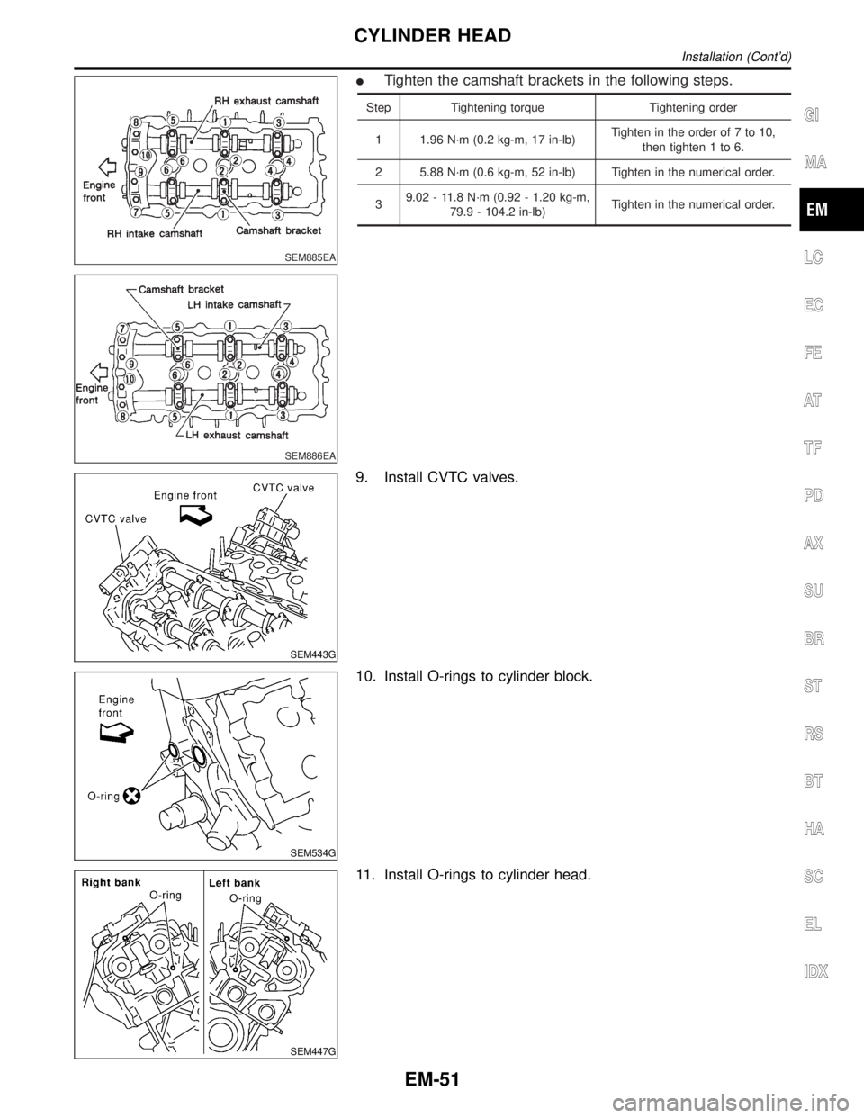
ITighten the camshaft brackets in the following steps.
Step Tightening torque Tightening order
1 1.96 N´m (0.2 kg-m, 17 in-lb)Tighten in the order of 7 to 10,
then tighten 1 to 6.
2 5.88 N´m (0.6 kg-m, 52 in-lb) Tighten in the numerical order.
39.02 - 11.8 N´m (0.92 - 1.20 kg-m,
79.9 - 104.2 in-lb)Tighten in the numerical order.
SEM443G
9. Install CVTC valves.
SEM534G
10. Install O-rings to cylinder block.
SEM447G
11. Install O-rings to cylinder head.
GI
MA
LC
EC
FE
AT
TF
PD
AX
SU
BR
ST
RS
BT
HA
SC
EL
IDX
CYLINDER HEAD
Installation (Cont'd)
EM-51
Page 1709 of 2395
SEM843E
SEM321AA
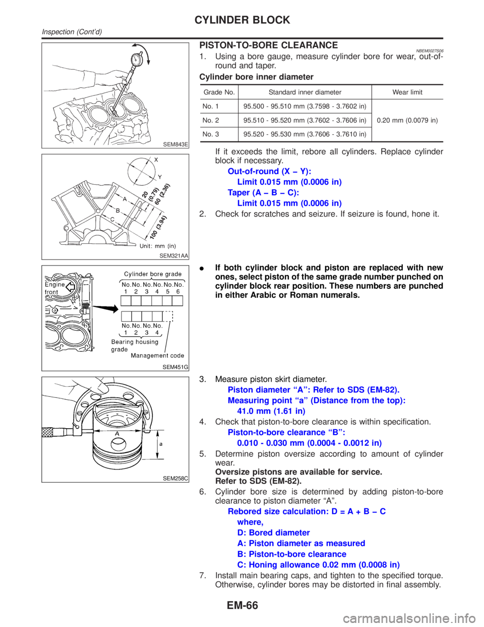
PISTON-TO-BORE CLEARANCENBEM0027S061. Using a bore gauge, measure cylinder bore for wear, out-of-
round and taper.
Cylinder bore inner diameter
Grade No. Standard inner diameter Wear limit
No. 1 95.500 - 95.510 mm (3.7598 - 3.7602 in)
0.20 mm (0.0079 in) No. 2 95.510 - 95.520 mm (3.7602 - 3.7606 in)
No. 3 95.520 - 95.530 mm (3.7606 - 3.7610 in)
If it exceeds the limit, rebore all cylinders. Replace cylinder
block if necessary.
Out-of-round (X þ Y):
Limit 0.015 mm (0.0006 in)
Taper (AþBþC):
Limit 0.015 mm (0.0006 in)
2. Check for scratches and seizure. If seizure is found, hone it.
SEM451G
IIf both cylinder block and piston are replaced with new
ones, select piston of the same grade number punched on
cylinder block rear position. These numbers are punched
in either Arabic or Roman numerals.
SEM258C
3. Measure piston skirt diameter.
Piston diameter ªAº: Refer to SDS (EM-82).
Measuring point ªaº (Distance from the top):
41.0 mm (1.61 in)
4. Check that piston-to-bore clearance is within specification.
Piston-to-bore clearance ªBº:
0.010 - 0.030 mm (0.0004 - 0.0012 in)
5. Determine piston oversize according to amount of cylinder
wear.
Oversize pistons are available for service.
Refer to SDS (EM-82).
6. Cylinder bore size is determined by adding piston-to-bore
clearance to piston diameter ªAº.
Rebored size calculation: D = A+BþC
where,
D: Bored diameter
A: Piston diameter as measured
B: Piston-to-bore clearance
C: Honing allowance 0.02 mm (0.0008 in)
7. Install main bearing caps, and tighten to the specified torque.
Otherwise, cylinder bores may be distorted in final assembly.
CYLINDER BLOCK
Inspection (Cont'd)
EM-66
Page 1712 of 2395
SEM280G
AEM027
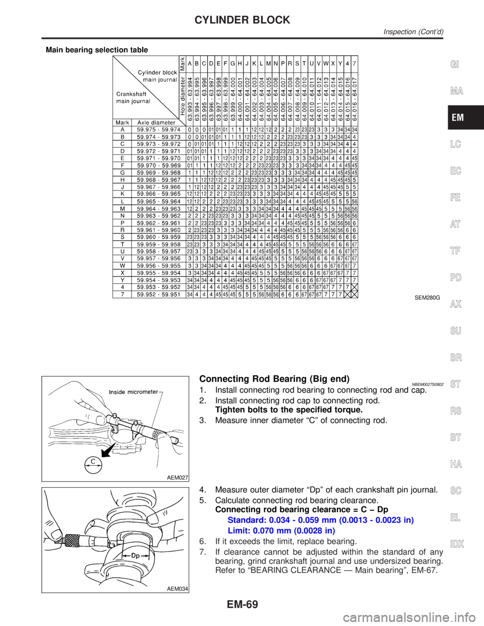
Connecting Rod Bearing (Big end)NBEM0027S08021. Install connecting rod bearing to connecting rod and cap.
2. Install connecting rod cap to connecting rod.
Tighten bolts to the specified torque.
3. Measure inner diameter ªCº of connecting rod.
AEM034
4. Measure outer diameter ªDpº of each crankshaft pin journal.
5. Calculate connecting rod bearing clearance.
Connecting rod bearing clearance=CþDp
Standard: 0.034 - 0.059 mm (0.0013 - 0.0023 in)
Limit: 0.070 mm (0.0028 in)
6. If it exceeds the limit, replace bearing.
7. If clearance cannot be adjusted within the standard of any
bearing, grind crankshaft journal and use undersized bearing.
Refer to ªBEARING CLEARANCE Ð Main bearingº, EM-67.
GI
MA
LC
EC
FE
AT
TF
PD
AX
SU
BR
ST
RS
BT
HA
SC
EL
IDX
CYLINDER BLOCK
Inspection (Cont'd)
EM-69
Page 1716 of 2395
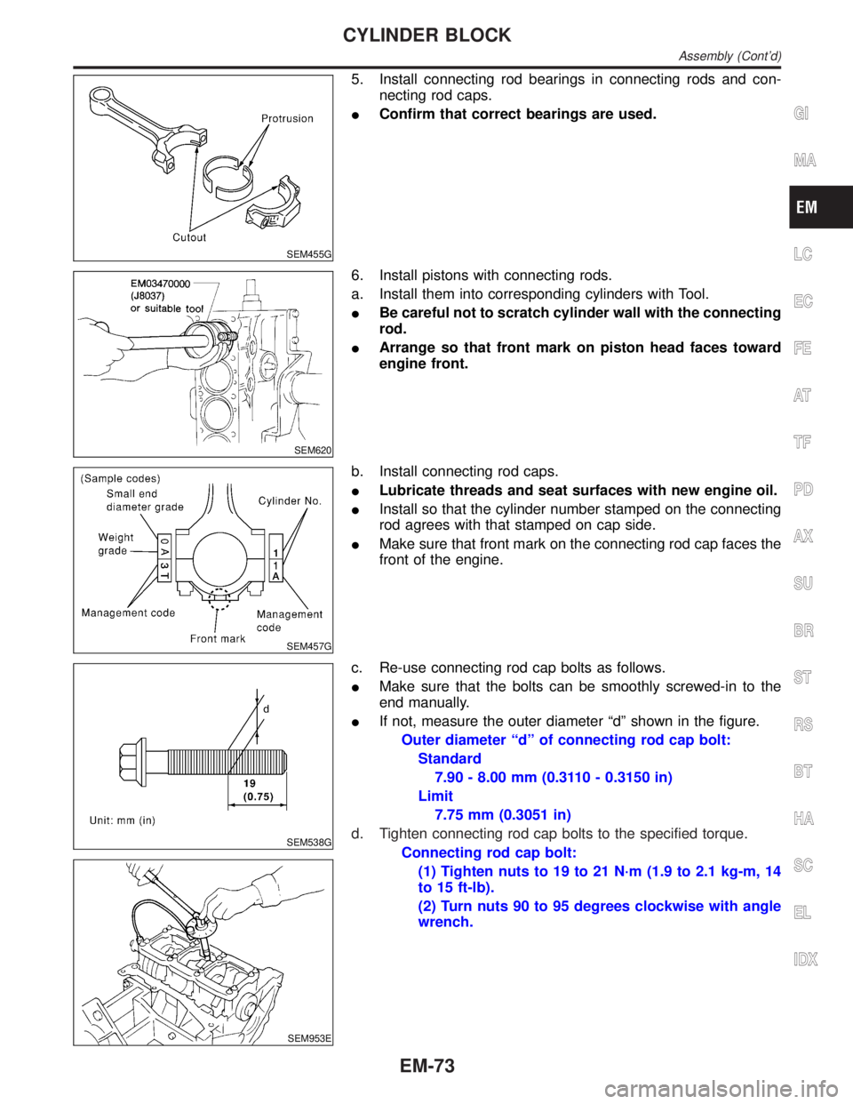
SEM455G
5. Install connecting rod bearings in connecting rods and con-
necting rod caps.
IConfirm that correct bearings are used.
SEM620
6. Install pistons with connecting rods.
a. Install them into corresponding cylinders with Tool.
IBe careful not to scratch cylinder wall with the connecting
rod.
IArrange so that front mark on piston head faces toward
engine front.
SEM457G
b. Install connecting rod caps.
ILubricate threads and seat surfaces with new engine oil.
IInstall so that the cylinder number stamped on the connecting
rod agrees with that stamped on cap side.
IMake sure that front mark on the connecting rod cap faces the
front of the engine.
SEM538G
SEM953E
c. Re-use connecting rod cap bolts as follows.
IMake sure that the bolts can be smoothly screwed-in to the
end manually.
IIf not, measure the outer diameter ªdº shown in the figure.
Outer diameter ªdº of connecting rod cap bolt:
Standard
7.90 - 8.00 mm (0.3110 - 0.3150 in)
Limit
7.75 mm (0.3051 in)
d. Tighten connecting rod cap bolts to the specified torque.
Connecting rod cap bolt:
(1) Tighten nuts to 19 to 21 N´m (1.9 to 2.1 kg-m, 14
to 15 ft-lb).
(2) Turn nuts 90 to 95 degrees clockwise with angle
wrench.
GI
MA
LC
EC
FE
AT
TF
PD
AX
SU
BR
ST
RS
BT
HA
SC
EL
IDX
CYLINDER BLOCK
Assembly (Cont'd)
EM-73
Page 1737 of 2395
Removal and InstallationNBFE0005CAUTION:
IAlways replace exhaust gaskets with new ones when reassembling.
IWith engine running, check all tube connections for exhaust gas leaks, and entire system for
unusual noises.
ICheck to ensure that mounting brackets and mounting insulators are installed properly and free
from undue stress. Improper installation could result in excessive noise or vibration.
IDiscard any heated oxygen sensor which has been dropped from a height of more than 0.5 m (19.7
in) onto a hard surface such as a concrete floor; use a new one.
IBefore installing new oxygen sensor, clean exhaust system threads using Oxygen Sensor Thread
Cleaner tool J-43897-18 of J-43897-12 and approved anti-seize lubricant.
IDo not overtorque the oxygen sensor. Doing so may cause damage to the oxygen sensor, result-
ing in the MIL coming on.
EXHAUST SYSTEM
Removal and Installation
FE-8
Page 1740 of 2395

MEL874F
MEL875F
InstallationNBEL0146To install SMJ, tighten bolts until orange ªfulltightº mark appears
and then retighten to specified torque as required.
:3-5N´m
(0.3 - 0.5 kg-m, 26 - 43 in-lb)
CAUTION:
Do not overtighten bolts, otherwise, they may be damaged.
SUPER MULTIPLE JUNCTION (SMJ)
Installation