warning INFINITI QX4 2001 Factory Service Manual
[x] Cancel search | Manufacturer: INFINITI, Model Year: 2001, Model line: QX4, Model: INFINITI QX4 2001Pages: 2395, PDF Size: 43.2 MB
Page 1561 of 2395

GPS ANTENNA CHECK=NBEL0184S11
1 CHECK VOLTAGE FOR GPS ANTENNA
1. Disconnect GPS feeder cable connector from IVCS unit.
2. Turn ignition switch ON.
3. Check voltage at IVCS unit GPS feeder cable terminal.
SEL106W
Does approx. 5V exist?
Ye s©Replace GPS antenna.
No©Replace IVCS unit.
AIR BAG DIAGNOSES SENSOR UNIT
COMMUNICATION CHECK
NBEL0184S12
1 AIR BAG OPERATION CHECK
Turn ignition switch ON and check air bag warning lamp operation. (For details, refer to RS-38.)
Does air bag warning lamp operate properly?
Ye s©Check harness connector connection between air bag diagnosis sensor unit and IVCS
unit.
No©Check supplemental restraint system. Refer to RS-29.
SMART ENTRANCE CONTROL UNIT COMMUNICATION
CHECK
NBEL0184S13
1 CHECK SMART ENTRANCE CONTROL UNIT OPERATION
Check the system related smart entrance control unit operation. (e.g.: power door lock, power window)
Does the system operate properly?
Ye s©Check harness for open or short between smart entrance control unit and IVCS unit.
No©Check smart entrance control unit. Refer to ªSMART ENTRANCE CONTROL UNITº in
the Service Manual. (EL-324)
INFINITI COMMUNICATOR (IVCS)
Trouble Diagnoses (Cont'd)
EL-376
Page 1565 of 2395

SEL528V
4. Touch ªBACKº key of CONSULT-II until ªSELECT SYSTEMº
appears, then turn off CONSULT-II.
5. Turn ignition switch to the OFF position.
6. Disconnect CONSULT-II DDL connector.
7. Start the engine.
8. Touch the ªMAYDAYº or ªINFORMATIONº switches. Then the
system will call the demonstration center.
SEL529V
9. Check INFINITI Communicator operation.
IIf contact with Communicator Response Center is successful,
system is OK.
NOTE:
During the system contact to Communicator Response Cen-
ter in demonstration mode, ªREDIALº and ªNO SERVICEº indi-
cators blink alternately.
SEL530V
IIf ªNO SERVICEº indicator illuminates and the contact to Com-
municator Response Center is unsuccessful, retry from other
location where the cellular connection seems good. (e.g.;
move the vehicle outside of the workshop and retry.)
NOTE:
If ªNO SERVICEº indicator frequently illuminates from a loca-
tion where the cellular connection seems good, check the con-
nection of the feeder cable for the cellular phone antenna.
SEL531V
IIf ªREDIALº indicator lamp illuminates and the contact to Com-
municator Response Center is unsuccessful, the cellular net-
work is busy or there are no open cellular channels. The sys-
tem will redial automatically.
NOTE:
If redial fails several times, confirm whether the roaming
agreement of customer's cellular provider at the vehicle loca-
tion is available or not.
WARNING:
IMake sure to turn the demonstration mode OFF before
returning the vehicle to the owner.
IIn the demonstration mode, any service from Communica-
tor Response Center is not available. Therefore, even if
the customer encounters an emergency, no service will be
dispatched.
INFINITI COMMUNICATOR (IVCS)
Demonstration Mode (Cont'd)
EL-380
Page 1642 of 2395
NBEL0145
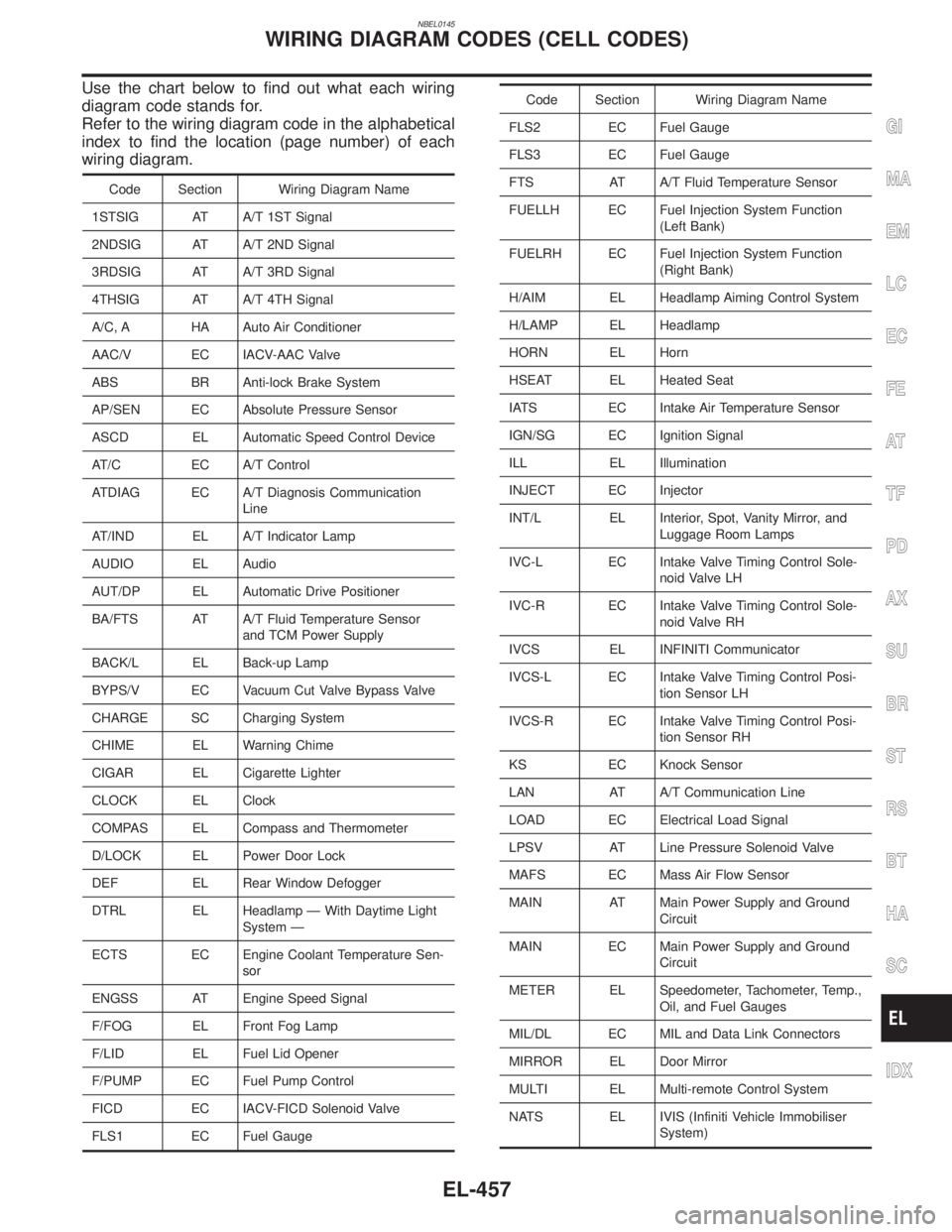
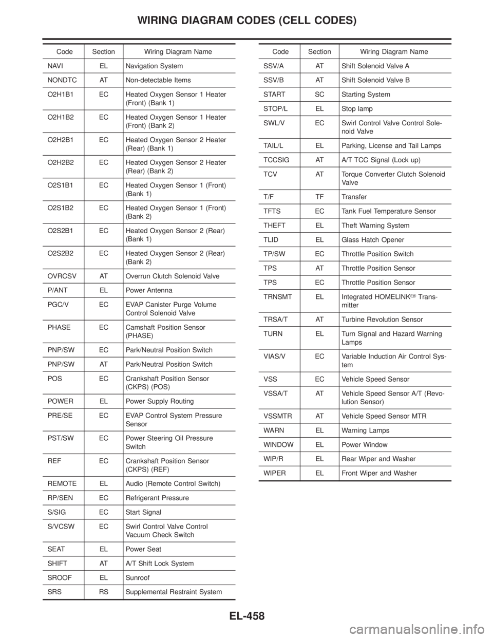
Use the chart below to find out what each wiring
diagram code stands for.
Refer to the wiring diagram code in the alphabetical
index to find the location (page number) of each
wiring diagram.
Code Section Wiring Diagram Name
1STSIG AT A/T 1ST Signal
2NDSIG AT A/T 2ND Signal
3RDSIG AT A/T 3RD Signal
4THSIG AT A/T 4TH Signal
A/C, A HA Auto Air Conditioner
AAC/V EC IACV-AAC Valve
ABS BR Anti-lock Brake System
AP/SEN EC Absolute Pressure Sensor
ASCD EL Automatic Speed Control Device
AT/C EC A/T Control
ATDIAG EC A/T Diagnosis Communication
Line
AT/IND EL A/T Indicator Lamp
AUDIO EL Audio
AUT/DP EL Automatic Drive Positioner
BA/FTS AT A/T Fluid Temperature Sensor
and TCM Power Supply
BACK/L EL Back-up Lamp
BYPS/V EC Vacuum Cut Valve Bypass Valve
CHARGE SC Charging System
CHIME EL Warning Chime
CIGAR EL Cigarette Lighter
CLOCK EL Clock
COMPAS EL Compass and Thermometer
D/LOCK EL Power Door Lock
DEF EL Rear Window Defogger
DTRL EL Headlamp Ð With Daytime Light
System Ð
ECTS EC Engine Coolant Temperature Sen-
sor
ENGSS AT Engine Speed Signal
F/FOG EL Front Fog Lamp
F/LID EL Fuel Lid Opener
F/PUMP EC Fuel Pump Control
FICD EC IACV-FICD Solenoid Valve
FLS1 EC Fuel Gauge
Code Section Wiring Diagram Name
FLS2 EC Fuel Gauge
FLS3 EC Fuel Gauge
FTS AT A/T Fluid Temperature Sensor
FUELLH EC Fuel Injection System Function
(Left Bank)
FUELRH EC Fuel Injection System Function
(Right Bank)
H/AIM EL Headlamp Aiming Control System
H/LAMP EL Headlamp
HORN EL Horn
HSEAT EL Heated Seat
IATS EC Intake Air Temperature Sensor
IGN/SG EC Ignition Signal
ILL EL Illumination
INJECT EC Injector
INT/L EL Interior, Spot, Vanity Mirror, and
Luggage Room Lamps
IVC-L EC Intake Valve Timing Control Sole-
noid Valve LH
IVC-R EC Intake Valve Timing Control Sole-
noid Valve RH
IVCS EL INFINITI Communicator
IVCS-L EC Intake Valve Timing Control Posi-
tion Sensor LH
IVCS-R EC Intake Valve Timing Control Posi-
tion Sensor RH
KS EC Knock Sensor
LAN AT A/T Communication Line
LOAD EC Electrical Load Signal
LPSV AT Line Pressure Solenoid Valve
MAFS EC Mass Air Flow Sensor
MAIN AT Main Power Supply and Ground
Circuit
MAIN EC Main Power Supply and Ground
Circuit
METER EL Speedometer, Tachometer, Temp.,
Oil, and Fuel Gauges
MIL/DL EC MIL and Data Link Connectors
MIRROR EL Door Mirror
MULTI EL Multi-remote Control System
NATS EL IVIS (Infiniti Vehicle Immobiliser
System)
GI
MA
EM
LC
EC
FE
AT
TF
PD
AX
SU
BR
ST
RS
BT
HA
SC
IDX
WIRING DIAGRAM CODES (CELL CODES)
EL-457
Page 1643 of 2395
Code Section Wiring Diagram Name
NAVI EL Navigation System
NONDTC AT Non-detectable Items
O2H1B1 EC Heated Oxygen Sensor 1 Heater
(Front) (Bank 1)
O2H1B2 EC Heated Oxygen Sensor 1 Heater
(Front) (Bank 2)
O2H2B1 EC Heated Oxygen Sensor 2 Heater
(Rear) (Bank 1)
O2H2B2 EC Heated Oxygen Sensor 2 Heater
(Rear) (Bank 2)
O2S1B1 EC Heated Oxygen Sensor 1 (Front)
(Bank 1)
O2S1B2 EC Heated Oxygen Sensor 1 (Front)
(Bank 2)
O2S2B1 EC Heated Oxygen Sensor 2 (Rear)
(Bank 1)
O2S2B2 EC Heated Oxygen Sensor 2 (Rear)
(Bank 2)
OVRCSV AT Overrun Clutch Solenoid Valve
P/ANT EL Power Antenna
PGC/V EC EVAP Canister Purge Volume
Control Solenoid Valve
PHASE EC Camshaft Position Sensor
(PHASE)
PNP/SW EC Park/Neutral Position Switch
PNP/SW AT Park/Neutral Position Switch
POS EC Crankshaft Position Sensor
(CKPS) (POS)
POWER EL Power Supply Routing
PRE/SE EC EVAP Control System Pressure
Sensor
PST/SW EC Power Steering Oil Pressure
Switch
REF EC Crankshaft Position Sensor
(CKPS) (REF)
REMOTE EL Audio (Remote Control Switch)
RP/SEN EC Refrigerant Pressure
S/SIG EC Start Signal
S/VCSW EC Swirl Control Valve Control
Vacuum Check Switch
SEAT EL Power Seat
SHIFT AT A/T Shift Lock System
SROOF EL Sunroof
SRS RS Supplemental Restraint SystemCode Section Wiring Diagram Name
SSV/A AT Shift Solenoid Valve A
SSV/B AT Shift Solenoid Valve B
START SC Starting System
STOP/L EL Stop lamp
SWL/V EC Swirl Control Valve Control Sole-
noid Valve
TAIL/L EL Parking, License and Tail Lamps
TCCSIG AT A/T TCC Signal (Lock up)
TCV AT Torque Converter Clutch Solenoid
Valve
T/F TF Transfer
TFTS EC Tank Fuel Temperature Sensor
THEFT EL Theft Warning System
TLID EL Glass Hatch Opener
TP/SW EC Throttle Position Switch
TPS AT Throttle Position Sensor
TPS EC Throttle Position Sensor
TRNSMT EL Integrated HOMELINKYTrans-
mitter
TRSA/T AT Turbine Revolution Sensor
TURN EL Turn Signal and Hazard Warning
Lamps
VIAS/V EC Variable Induction Air Control Sys-
tem
VSS EC Vehicle Speed Sensor
VSSA/T AT Vehicle Speed Sensor A/T (Revo-
lution Sensor)
VSSMTR AT Vehicle Speed Sensor MTR
WARN EL Warning Lamps
WINDOW EL Power Window
WIP/R EL Rear Wiper and Washer
WIPER EL Front Wiper and Washer
WIRING DIAGRAM CODES (CELL CODES)
EL-458
Page 1658 of 2395
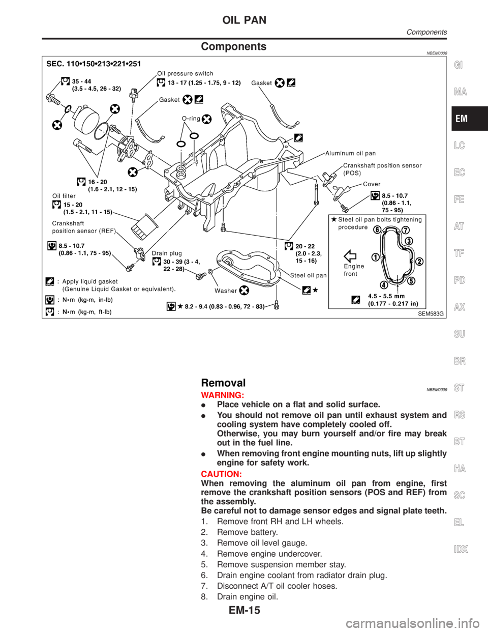
ComponentsNBEM0008
SEM583G
RemovalNBEM0009WARNING:
IPlace vehicle on a flat and solid surface.
IYou should not remove oil pan until exhaust system and
cooling system have completely cooled off.
Otherwise, you may burn yourself and/or fire may break
out in the fuel line.
IWhen removing front engine mounting nuts, lift up slightly
engine for safety work.
CAUTION:
When removing the aluminum oil pan from engine, first
remove the crankshaft position sensors (POS and REF) from
the assembly.
Be careful not to damage sensor edges and signal plate teeth.
1. Remove front RH and LH wheels.
2. Remove battery.
3. Remove oil level gauge.
4. Remove engine undercover.
5. Remove suspension member stay.
6. Drain engine coolant from radiator drain plug.
7. Disconnect A/T oil cooler hoses.
8. Drain engine oil.
GI
MA
LC
EC
FE
AT
TF
PD
AX
SU
BR
ST
RS
BT
HA
SC
EL
IDX
OIL PAN
Components
EM-15
Page 1700 of 2395
Removal and InstallationNBEM0042WARNING:
ISituate vehicle on a flat and solid surface.
IPlace chocks at front and back of rear wheels.
IDo not remove engine until exhaust system has com-
pletely cooled off. Otherwise, you may burn yourself
and/or fire may break out in fuel line.
IFor safety during subsequent steps, the tension of wires
should be slackened against the engine.
IBefore disconnecting fuel hose, release fuel pressure
from fuel line.
Refer to EC-39, ªFuel Pressure Releaseº.
IBefore removing front axle from transmission, place
safety stands under designated front supporting points.
Refer to GI section for lifting points and towing.
IBe sure to hoist engine and transmission in a safe man-
ner.
IFor engines not equipped with engine slingers, attach
proper slingers and bolts described in PARTS CATALOG.
CAUTION:
IWhen lifting engine, be careful not to strike adjacent parts,
especially accelerator wire casing, brake lines, and brake
master cylinder.
IIn hoisting the engine, always use engine slingers in a
safe manner.
IBefore separating engine and transmission, remove
crankshaft position sensor (POS) from the assembly.
IAlways take extra care not to damage edge of crankshaft
position sensor (POS), or ring gear teeth.GI
MA
LC
EC
FE
AT
TF
PD
AX
SU
BR
ST
RS
BT
HA
SC
EL
IDX
ENGINE ASSEMBLY
Removal and Installation
EM-57
Page 1733 of 2395
Removal and InstallationNBFE0004WARNING:
When replacing fuel line parts, be sure to observe the follow-
ing:
IPut a ªCAUTION: INFLAMMABLEº sign in workshop.
IDo not smoke while servicing fuel system. Keep open
flames and sparks away from work area.
IBe sure to furnish the workshop with a CO
2fire extin-
guisher.
CAUTION:
IBefore removing fuel line parts, carry out the following
procedures:
a) Put drained fuel in an explosion-proof container and put
lid on securely.
b) Release fuel pressure from fuel line. Refer to MA-16,
ªChanging Fuel Filterº.
c) Disconnect battery ground cable.
IAlways replace O-ring with new ones.
IDo not kink or twist hose and tube when they are installed.
IDo not tighten hose clamps excessively to avoid damag-
ing hoses.
IWhen installing fuel check valve, be careful of its desig-
nated direction. Refer to EC-32, ªEVAPORATIVE EMIS-
SION SYSTEMº.
IAfter installation, run engine and check for fuel leaks at
connections.
FUEL SYSTEM
Removal and Installation
FE-4
Page 1748 of 2395

PrecautionsNBGI0001Observe the following precautions to ensure safe and proper
servicing. These precautions are not described in each indi-
vidual section.
SGI646
PRECAUTIONS FOR SUPPLEMENTAL RESTRAINT
SYSTEM (SRS) ªAIR BAGº AND ªSEAT BELT
PRE-TENSIONERº
NBGI0001S01The Supplemental Restraint System such as ªAIR BAGº and ªSEAT
BELT PRE-TENSIONERº used along with a seat belt, helps to
reduce the risk or severity of injury to the driver and front passen-
ger for certain types of collision. The SRS system composition
which is available to INFINITI QX4 is as follows:
IFor a frontal collision
The Supplemental Restraint System consists of driver air bag
module (located in the center of the steering wheel), front pas-
senger air bag module (located on the instrument panel on
passenger side), seat belt pre-tensioners, a diagnosis sensor
unit, warning lamp, wiring harness and spiral cable.
IFor a side collision
The Supplemental Restraint System consists of side air bag
module (located in the outer side of front seat), satellite sensor,
diagnosis sensor unit (one of components of air bags for a
frontal collision), wiring harness, warning lamp (one of compo-
nents of air bags for a frontal collision).
Information necessary to service the system safely is included in
theRS sectionof this Service Manual.
WARNING:
ITo avoid rendering the SRS inoperative, which could
increase the risk of personal injury or death in the event
of a collision which would result in air bag inflation, all
maintenance must be performed by an authorized INFINITI
dealer.
IImproper maintenance, including incorrect removal and
installation of the SRS, can lead to personal injury caused
by unintentional activation of the system. For removal of
Spiral Cable and Air Bag Module, see the RS section.
IDo not use electrical test equipment on any circuit related
to the SRS unless instructed to in this Service Manual.
Spiral cable and wiring harnesses covered with yellow
insulation tape either just before the harness connectors
or for the complete harness are related to the SRS.
PRECAUTIONS FOR IVIS (INFINITI VEHICLE
IMMOBILIZER SYSTEM Ð NATS)
NBGI0001S08IVIS (NATS) will immobilize the engine if someone tries to start it
without the registered key of IVIS (NATS).
Both of the originally supplied ignition key IDs have been IVIS
(NATS) registered.
MA
EM
LC
EC
FE
AT
TF
PD
AX
SU
BR
ST
RS
BT
HA
SC
EL
IDX
PRECAUTIONS
Precautions
GI-3
Page 1749 of 2395

The security indicator is located on the instrument panel. The indi-
cator blinks when the ignition switch is in OFF or ACC position.
Therefore, IVIS (NATS) warns outsiders that the vehicle is
equipped with the anti-theft system.
IWhen IVIS (NATS) detects trouble, the security indicator lamp
lights up while ignition switch is in ON position.
This lighting up indicates that the anti-theft is not functioning,
so prompt service is required.
IWhen servicing IVIS (NATS) (trouble diagnoses, system initial-
ization and additional registration of other IVIS (NATS) ignition
key IDs), CONSULT-II hardware and CONSULT-II IVIS (NATS)
software is necessary.
Regarding the procedures of IVIS (NATS) initialization and
IVIS (NATS) ignition key ID registration, refer to CONSULT-II
operation manual, IVIS/NVIS.
Therefore, CONSULT-II IVIS (NATS) software (program card
and operation manual) must be kept strictly confidential to
maintain the integrity of the anti-theft function.
IWhen servicing IVIS (NATS) (trouble diagnoses, system initial-
ization and additional registration of other IVIS (NATS) ignition
key IDs), it may be necessary to re-register original key iden-
tification. Therefore, be sure to receive all keys from vehicle
owner.
A maximum of five key IDs can be registered into IVIS (NATS).
IWhen failing to start the engine first time using the key of IVIS
(NATS) (for example, when interference is caused by another
IVIS (NATS) key, an automated full road device or automated
payment device on the key ring), restart as follows.
a) Leave the ignition switch in ON position for approximately 5
seconds.
b) Turn ignition switch to OFF or LOCK position and wait approxi-
mately 5 seconds.
c) Repeat step 1 and 2.
d) Restart the engine while holding the device (which may have
caused the interference) separate from the registered NATS
key. If the no start condition re-occurs, NISSAN recommends
placing the registered IVIS (NATS) key on a separate key ring
to avoid interference from other devices.
PRECAUTIONS FOR INFINITI COMMUNICATOR (IVCS)NBGI0001S09The purpose of INFINITI Communicator is to increase security for
the vehicle owner by providing a convenient way to contact the
most appropriate emergency assistance provider during an emer-
gency.
Improper operation of the system may result in a police response.
The theft warning system also activates INFINITI Communicator.
For details, refer to INFINITI Communicator (IVCS) in the EL sec-
tion.
PRECAUTIONS
Precautions (Cont'd)
GI-4
Page 1751 of 2395
IClean all disassembled parts in the designated liquid or solvent
prior to inspection or assembly.
IReplace oil seals, gaskets, packings, O-rings, locking washers,
cotter pins, self-locking nuts, etc. with new ones.
IReplace inner and outer races of tapered roller bearings and
needle bearings as a set.
IArrange the disassembled parts in accordance with their
assembled locations and sequence.
IDo not touch the terminals of electrical components which use
microcomputers (such as ECMs).
Static electricity may damage internal electronic components.
IAfter disconnecting vacuum or air hoses, attach a tag to indi-
cate the proper connection.
IUse only the fluids and lubricants specified in this manual.
IUse approved bonding agent, sealants or their equivalents
when required.
IUse tools and recommended special tools where specified for
safe and efficient service repairs.
IWhen repairing the fuel, oil, water, vacuum or exhaust
systems, check all affected lines for leaks.
IDispose of drained oil or the solvent used for cleaning parts in
an appropriate manner.
WARNING:
To prevent ECM from storing the diagnostic trouble codes, do
not carelessly disconnect the harness connectors which are
related to the engine control system and TCM (Transmission
Control Module) system. The connectors should be discon-
nected only when working according to the WORK FLOW of
TROUBLE DIAGNOSES in EC and AT sections.
SGI787
PRECAUTIONS FOR MULTIPORT FUEL INJECTION
SYSTEM OR ENGINE CONTROL SYSTEM
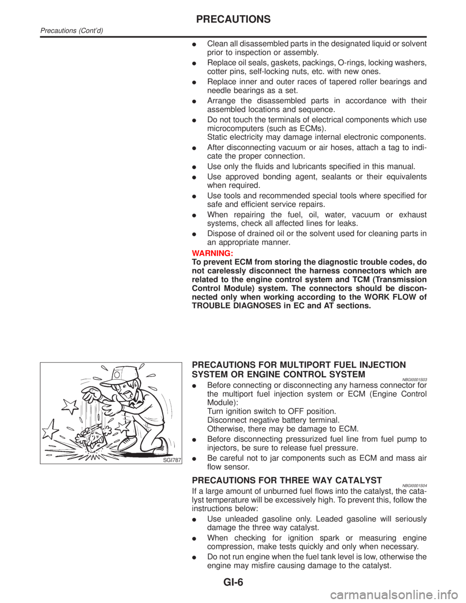
NBGI0001S03IBefore connecting or disconnecting any harness connector for
the multiport fuel injection system or ECM (Engine Control
Module):
Turn ignition switch to OFF position.
Disconnect negative battery terminal.
Otherwise, there may be damage to ECM.
IBefore disconnecting pressurized fuel line from fuel pump to
injectors, be sure to release fuel pressure.
IBe careful not to jar components such as ECM and mass air
flow sensor.
PRECAUTIONS FOR THREE WAY CATALYSTNBGI0001S04If a large amount of unburned fuel flows into the catalyst, the cata-
lyst temperature will be excessively high. To prevent this, follow the
instructions below:
IUse unleaded gasoline only. Leaded gasoline will seriously
damage the three way catalyst.
IWhen checking for ignition spark or measuring engine
compression, make tests quickly and only when necessary.
IDo not run engine when the fuel tank level is low, otherwise the
engine may misfire causing damage to the catalyst.
PRECAUTIONS
Precautions (Cont'd)
GI-6