display INFINITI QX4 2001 Factory Service Manual
[x] Cancel search | Manufacturer: INFINITI, Model Year: 2001, Model line: QX4, Model: INFINITI QX4 2001Pages: 2395, PDF Size: 43.2 MB
Page 1807 of 2395

RHA273D
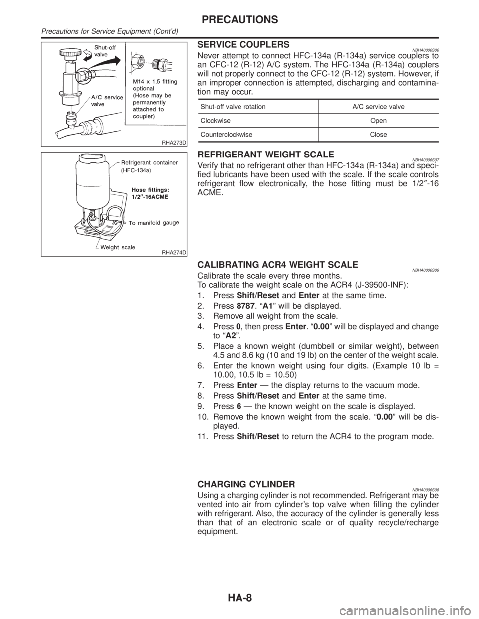
SERVICE COUPLERSNBHA0006S06Never attempt to connect HFC-134a (R-134a) service couplers to
an CFC-12 (R-12) A/C system. The HFC-134a (R-134a) couplers
will not properly connect to the CFC-12 (R-12) system. However, if
an improper connection is attempted, discharging and contamina-
tion may occur.
Shut-off valve rotation A/C service valve
Clockwise Open
Counterclockwise Close
RHA274D
REFRIGERANT WEIGHT SCALENBHA0006S07Verify that no refrigerant other than HFC-134a (R-134a) and speci-
fied lubricants have been used with the scale. If the scale controls
refrigerant flow electronically, the hose fitting must be 1/2²-16
ACME.
CALIBRATING ACR4 WEIGHT SCALENBHA0006S09Calibrate the scale every three months.
To calibrate the weight scale on the ACR4 (J-39500-INF):
1. PressShift/ResetandEnterat the same time.
2. Press8787.ªA1º will be displayed.
3. Remove all weight from the scale.
4. Press0, then pressEnter.ª0.00º will be displayed and change
to ªA2º.
5. Place a known weight (dumbbell or similar weight), between
4.5 and 8.6 kg (10 and 19 lb) on the center of the weight scale.
6. Enter the known weight using four digits. (Example 10 lb =
10.00, 10.5 lb = 10.50)
7. PressEnterÐ the display returns to the vacuum mode.
8. PressShift/ResetandEnterat the same time.
9. Press6Ð the known weight on the scale is displayed.
10. Remove the known weight from the scale. ª0.00º will be dis-
played.
11. PressShift/Resetto return the ACR4 to the program mode.
CHARGING CYLINDERNBHA0006S08Using a charging cylinder is not recommended. Refrigerant may be
vented into air from cylinder's top valve when filling the cylinder
with refrigerant. Also, the accuracy of the cylinder is generally less
than that of an electronic scale or of quality recycle/recharge
equipment.
PRECAUTIONS
Precautions for Service Equipment (Cont'd)
HA-8
Page 1823 of 2395

RHA328HA
DISPLAY SCREENNBHA0016S01Displays the operational status of the system.
AUTO SWITCHNBHA0016S02The compressor, intake doors, air mix door, outlet doors, and blower speed are automatically controlled so
that the in-vehicle temperature will reach, and be maintained at the set temperature selected by the operator.
ECON SWITCHNBHA0016S03By pressing the ECON switch, the display should indicate ECON and the compressor always turns OFF. With
the compressor OFF, the system will not remove heat (cool) or de-humidify. The system will maintain the in-
vehicle temperature at the set temperature when the set temperature is above the ambient (outside) tempera-
ture. The system will set the intake doors to the outside air position.
TEMPERATURE SWITCH (POTENTIO TEMPERATURE CONTROL) WITHOUT NAVIGATION
SYSTEM
NBHA0016S04Increases or decreases the set temperature.
OFF SWITCHNBHA0016S05The compressor and blower are OFF, the intake doors are set to the outside air position, and the air outlet
doors are set to the foot (80% foot and 20% defrost) position.
FAN SWITCHNBHA0016S06Manually controls the blower speed. Four speeds are available for manual control (as shown on the display
screen):
low
, medium low, medium high, high
RECIRCULATION (REC) SWITCHNBHA0016S07OFF position: Outside air is drawn into the passenger compartment.
ON position: Interior air is recirculated inside the vehicle.
DEFROSTER (DEF) SWITCHNBHA0016S08Positions the air outlet doors to the defrost position. Also positions the intake doors to the outside air position.
MODE SWITCHNBHA0016S09Controls the air discharge outlets.
TEMPERATURE DIAL (POTENTIO TEMPERATURE CONTROL) WITH NAVIGATION SYSTEMNBHA0016S10Increases or decreases the set temperature.
AMB (AMBIENT) SWITCH (WITH NAVIGATION SYSTEM)NBHA0016S11Shows the ambient (outside) air temperature on the display screen for 5 seconds.
DESCRIPTION
Control Operation (Cont'd)
HA-24
Page 1844 of 2395

STEP-BY-STEP PROCEDURE=NBHA0021S02Without Navigation SystemNBHA0021S0201
1 SET IN SELF-DIAGNOSTIC MODE
1. Turn ignition switch ON.
2. Set in self-diagnostic mode as follows. Within 10 seconds after starting engine (ignition switch is turned ªONº.), press
switch for at least 5 seconds.
©GO TO 2.
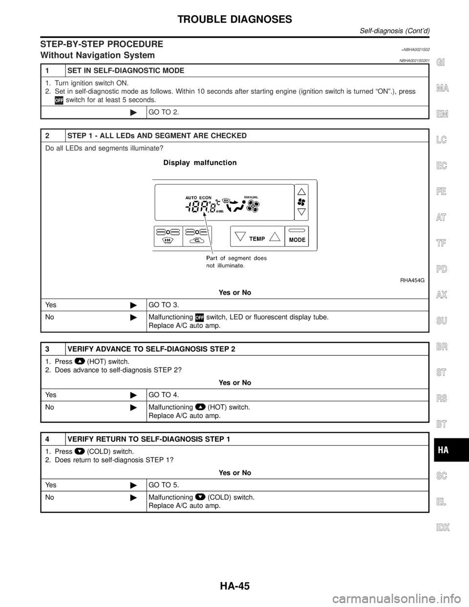
2 STEP 1 - ALL LEDs AND SEGMENT ARE CHECKED
Do all LEDs and segments illuminate?
RHA454G
YesorNo
Ye s©GO TO 3.
No©Malfunctioning
switch, LED or fluorescent display tube.
Replace A/C auto amp.
3 VERIFY ADVANCE TO SELF-DIAGNOSIS STEP 2
1. Press(HOT) switch.
2. Does advance to self-diagnosis STEP 2?
YesorNo
Ye s©GO TO 4.
No©Malfunctioning
(HOT) switch.
Replace A/C auto amp.
4 VERIFY RETURN TO SELF-DIAGNOSIS STEP 1
1. Press(COLD) switch.
2. Does return to self-diagnosis STEP 1?
YesorNo
Ye s©GO TO 5.
No©Malfunctioning
(COLD) switch.
Replace A/C auto amp.
GI
MA
EM
LC
EC
FE
AT
TF
PD
AX
SU
BR
ST
RS
BT
SC
EL
IDX
TROUBLE DIAGNOSES
Self-diagnosis (Cont'd)
HA-45
Page 1845 of 2395

5 STEP 2 - SENSOR CIRCUITS ARE CHECKED FOR OPEN OR SHORT CIRCUIT
Press(HOT) switch.
Does code No.
appear on the display?
RHA970DB
YesorNo
Ye s©GO TO 6.
No©GO TO 13.
6 STEP 3 - MODE DOOR AND INTAKE DOOR POSITIONS ARE CHECKED
Press(HOT) switch.
Does code No.
appear on the display?
RHA869DD
YesorNo
Ye s©GO TO 7.
No©GO TO 14.
TROUBLE DIAGNOSES
Self-diagnosis (Cont'd)
HA-46
Page 1846 of 2395

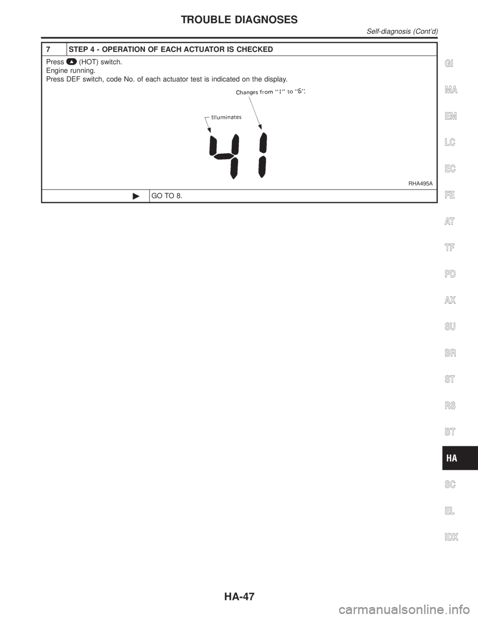
7 STEP 4 - OPERATION OF EACH ACTUATOR IS CHECKED
Press(HOT) switch.
Engine running.
Press DEF switch, code No. of each actuator test is indicated on the display.
RHA495A
©GO TO 8.
GI
MA
EM
LC
EC
FE
AT
TF
PD
AX
SU
BR
ST
RS
BT
SC
EL
IDX
TROUBLE DIAGNOSES
Self-diagnosis (Cont'd)
HA-47
Page 1848 of 2395

9 STEP 5 - TEMPERATURE OF EACH SENSOR IS CHECKED
Press(HOT) switch.
Code No.
appears on the display.
RHA492A
©GO TO 10.
10 CHECK AMBIENT SENSOR
Press(DEF) switch one time, temperature detected by ambient sensor is indicated on the display.
ECON shown in display indicates negative temperature reading.
NOTE:
If temperature shown on display greatly differs from actual temperature, check sensor circuit first, then inspect sensor.
RHA499G
OK or NG
OK©GO TO 11.
NG©Go to Ambient Sensor Circuit (HA-129).
GI
MA
EM
LC
EC
FE
AT
TF
PD
AX
SU
BR
ST
RS
BT
SC
EL
IDX
TROUBLE DIAGNOSES
Self-diagnosis (Cont'd)
HA-49
Page 1849 of 2395

11 CHECK IN-VEHICLE SENSOR
Press(DEF) switch the second time, temperature detected by in-vehicle sensor is indicated on the display screen.
ECON shown in display indicates negative temperature reading.
NOTE:
If temperature shown on display greatly differs from actual temperature, check sensor circuit first, then inspect sensor.
RHA500G
OK or NG
OK©GO TO 12.
NG©Go to In-vehicle Sensor Circuit (HA-132).
12 CHECK INTAKE SENSOR
Press(DEF) switch the third time, temperature detected by intake sensor is indicated on the display.
NOTE:
If temperature shown on display greatly differs from actual temperature, check sensor circuit first, then inspect sensor.
RHA500GB
OK or NG
OK©1. Press
(DEF) switch the fourth time. Display returns to original presentation 5.
2. Turn ignition switch OFF or
(AUTO) switch ON.
3. END
NG©Go to Intake Sensor Circuit (HA-139).
TROUBLE DIAGNOSES
Self-diagnosis (Cont'd)
HA-50
Page 1851 of 2395

14 CHECK MALFUNCTIONING DOOR MOTOR POSITION SWITCH
Mode or (and) intake door motor position switch(es) is (are) malfunctioning.
(If two or more mode or intake doors are out of order, corresponding code numbers blink respectively two times.)
MTBL0508
*1: If mode door motor harness connector is disconnected, the following display pattern will appear.
,,,,,Return to
*2: If intake door motor harness connector is disconnected, the following display pattern will appear.
,,,Return to
*3: HA-75
*4: HA-87
RHA168DA
RHA498A
©INSPECTION END
TROUBLE DIAGNOSES
Self-diagnosis (Cont'd)
HA-52
Page 1852 of 2395

AUXILIARY MECHANISM: TEMPERATURE SETTING TRIMMER=NBHA0021S03Without Navigation SystemNBHA0021S0301The trimmer compensates for differences in range of±3ÉC (±6ÉF) between temperature setting (displayed
digitally) and temperature felt by driver.
Operating procedures for this trimmer are as follows:
IBegin Self-diagnosis STEP 5 mode.
IPress
(fan) UP switch to set system in auxiliary mode.
IDisplay shows ª
º in auxiliary mechanism.
It takes approximately 3 seconds.
IPress either
(HOT) or(COLD) switch as desired. Temperature will change at a rate of 0.5ÉC (1ÉF)
each time a switch is pressed.
SHA197E
When battery cable is disconnected, trimmer operation is canceled. Temperature set becomes that of
initial condition, i.e. 0ÉC (0ÉF).
GI
MA
EM
LC
EC
FE
AT
TF
PD
AX
SU
BR
ST
RS
BT
SC
EL
IDX
TROUBLE DIAGNOSES
Self-diagnosis (Cont'd)
HA-53
Page 1854 of 2395

STEP-BY-STEP PROCEDURENBHA0021S05With Navigation SystemNBHA0021S0501
1 SET IN SELF-DIAGNOSTIC MODE
1. Turn ignition switch ON.
2. Set in self-diagnostic mode as follows. Within 10 seconds after starting engine (ignition switch is turned ªONº.), press
switch for at least 5 seconds.
©GO TO 2.
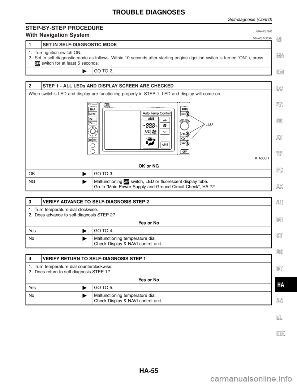
2 STEP 1 - ALL LEDs AND DISPLAY SCREEN ARE CHECKED
When switch's LED and display are functioning properly in STEP-1, LED and display will come on.
RHA860H
OK or NG
OK©GO TO 3.
NG©Malfunctioning
switch, LED or fluorescent display tube.
Go to ªMain Power Supply and Ground Circuit Checkº, HA-72.
3 VERIFY ADVANCE TO SELF-DIAGNOSIS STEP 2
1. Turn temperature dial clockwise.
2. Does advance to self-diagnosis STEP 2?
YesorNo
Ye s©GO TO 4.
No©Malfunctioning temperature dial.
Check Display & NAVI control unit.
4 VERIFY RETURN TO SELF-DIAGNOSIS STEP 1
1. Turn temperature dial counterclockwise.
2. Does return to self-diagnosis STEP 1?
YesorNo
Ye s©GO TO 5.
No©Malfunctioning temperature dial.
Check Display & NAVI control unit.
GI
MA
EM
LC
EC
FE
AT
TF
PD
AX
SU
BR
ST
RS
BT
SC
EL
IDX
TROUBLE DIAGNOSES
Self-diagnosis (Cont'd)
HA-55