4wd INFINITI QX4 2001 Factory User Guide
[x] Cancel search | Manufacturer: INFINITI, Model Year: 2001, Model line: QX4, Model: INFINITI QX4 2001Pages: 2395, PDF Size: 43.2 MB
Page 391 of 2395

ABS
DESCRIPTION...............................................................32
Purpose......................................................................32
Operation ...................................................................32
ABS Hydraulic Circuit ................................................32
System Components .................................................33
System Description ....................................................33
SENSOR.................................................................33
CONTROL UNIT (BUILT-IN ABS ACTUATOR AND
ELECTRIC UNIT)
.....................................................33
ABS ACTUATOR AND ELECTRIC UNIT....................33
G SENSOR (4WD MODELS ONLY)..........................34
Component Parts and Harness Connector
Location .....................................................................35
Schematic ..................................................................36
Wiring Diagram - ABS - .............................................37
ON BOARD DIAGNOSTIC SYSTEM
DESCRIPTION...............................................................41
Self-diagnosis ............................................................41
FUNCTION..............................................................41
SELF-DIAGNOSIS PROCEDURE..............................41
HOW TO READ SELF-DIAGNOSTIC RESULTS
(MALFUNCTION CODES)
........................................42
HOW TO ERASE SELF-DIAGNOSTIC RESULTS
(MALFUNCTION CODES)
........................................42
CONSULT-II ...............................................................43
CONSULT-II APPLICATION TO ABS..........................43
ECU (ABS CONTROL UNIT) PART NUMBER
MODE
.....................................................................43
CONSULT-II Inspection Procedure............................44
SELF-DIAGNOSIS PROCEDURE..............................44
SELF-DIAGNOSTIC RESULTS MODE.......................45
DATA MONITOR PROCEDURE................................46
ACTIVE TEST PROCEDURE....................................47
DATA MONITOR MODE...........................................48
ACTIVE TEST MODE...............................................48
TROUBLE DIAGNOSIS - INTRODUCTION..................49
How to Perform Trouble Diagnoses for Quick
and Accurate Repair ..................................................49
INTRODUCTION......................................................49
TROUBLE DIAGNOSIS - BASIC INSPECTION...........50
Preliminary Check......................................................50
Ground Circuit Check ................................................53
ABS ACTUATOR AND ELECTRIC UNIT GROUND.....53
TROUBLE DIAGNOSIS - GENERAL
DESCRIPTION...............................................................54
Malfunction Code/Symptom Chart.............................54
TROUBLE DIAGNOSES FOR SELF-DIAGNOSTIC
ITEMS.............................................................................56Wheel Sensor or Rotor ..............................................56
DIAGNOSTIC PROCEDURE.....................................56
ABS Actuator Solenoid Valve or Solenoid Valve
Relay ..........................................................................59
DIAGNOSTIC PROCEDURE.....................................59
Motor Relay or Motor.................................................61
DIAGNOSTIC PROCEDURE.....................................61
Low Voltage ...............................................................63
DIAGNOSTIC PROCEDURE.....................................63
G Sensor and Circuit .................................................65
DIAGNOSTIC PROCEDURE.....................................65
ELECTRICAL COMPONENT INSPECTION................67
Control Unit ................................................................68
DIAGNOSTIC PROCEDURE.....................................68
TROUBLE DIAGNOSES FOR SYMPTOMS.................69
1. ABS Works Frequently ..........................................69
2. Unexpected Pedal Action ......................................69
3. Long Stopping Distance ........................................70
4. ABS Does Not Work ..............................................71
5. Pedal Vibration and Noise.....................................71
6. Warning Lamp Does Not Come On When
Ignition Switch Is Turned On .....................................72
7. Warning Lamp Stays On When Ignition Switch
Is Turned On ..............................................................74
8. Vehicle Vibrates Excessively When ABS Is
Operating ...................................................................77
REMOVAL AND INSTALLATION.................................80
Front Wheel Sensor...................................................80
Rear Wheel Sensor ...................................................80
Front Sensor Rotor ....................................................81
REMOVAL...............................................................81
INSTALLATION........................................................81
Rear Sensor Rotor.....................................................81
REMOVAL...............................................................81
INSTALLATION........................................................81
G Sensor....................................................................81
ABS Actuator and Electric Unit..................................82
REMOVAL...............................................................82
INSTALLATION........................................................82
SERVICE DATA AND SPECIFICATIONS (SDS).........83
General Specifications ...............................................83
Disc Brake .................................................................83
Drum Brake................................................................83
Brake Pedal ...............................................................83
Parking Brake Control ...............................................84
CONTENTS(Cont'd)
BR-2
Page 397 of 2395

SBR995
Bleeding Brake System=NBBR0009CAUTION:
ICarefully monitor brake fluid level at master cylinder dur-
ing bleeding operation.
IIf master cylinder is suspected to have air inside, bleed air
from master cylinder first. Refer to ªInstallationº, ªMAS-
TER CYLINDERº, BR-18.
IFill reservoir with new brake fluid ªDOT 3º. Make sure it is
full at all times while bleeding air out of system.
IPlace a container under master cylinder to avoid spillage
of brake fluid.
ITurn ignition switch OFF and disconnect ABS actuator
and electric unit connectors or battery ground cable.
IBleed air in the following order.
1. LSV air bleeder (4WD)
2. Left rear brake
3. Right rear brake
4. Left front brake
5. Right front brake
SBR419C
1. Connect a transparent vinyl tube to air bleeder valve.
2. Fully depress brake pedal several times.
3. With brake pedal depressed, open air bleeder valve to release
air.
4. Close air bleeder valve.
5. Release brake pedal slowly.
6. Repeat steps 2. through 5. until clear brake fluid comes out of
air bleeder valve.
7. Tighten air bleeder valve.
:7-9N´m(0.7 - 0.9 kg-m, 61 - 78 in-lb)
ON-VEHICLE SERVICE
Bleeding Brake System
BR-8
Page 401 of 2395

InspectionNBBR0014CAUTION:
ICarefully monitor brake fluid level at master cylinder.
IUse new brake fluid ªDOT 3º.
IBe careful not to splash brake fluid on painted areas; it
may cause paint damage. If brake fluid is splashed on
paint areas, wash it away with water immediately.
IDepress pedal slowly when raising front brake pressure.
ICheck rear brake pressure 2 seconds after front brake
pressure reaches specified value.
IDisconnect harness connectors from ABS actuator and
electric unit before checking.
SBR212E
1. Park vehicle on a level surface with vehicle unloaded*.
* Fuel, radiator coolant and engine oil full. Spare tire, jack,
hand tools and mats in designated positions.
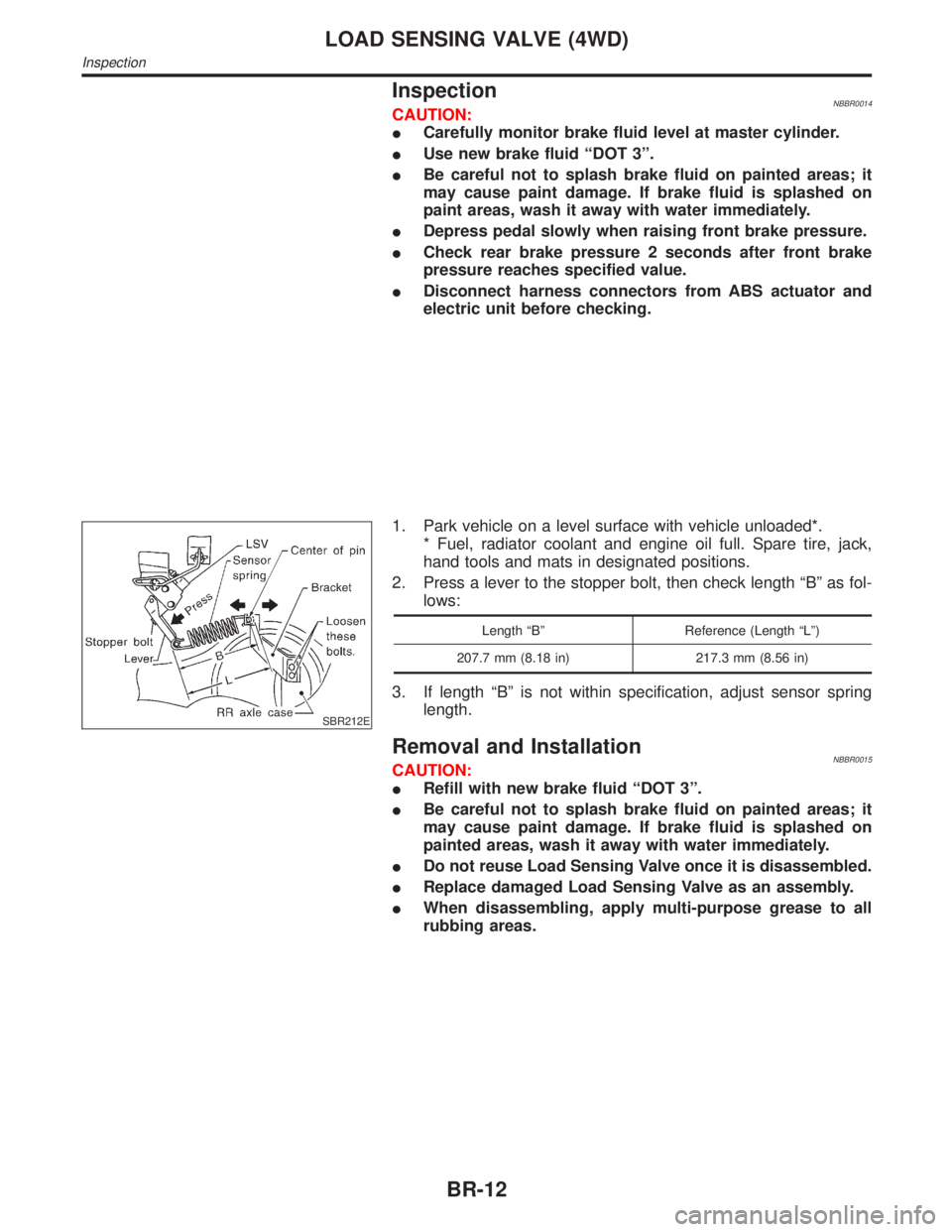
2. Press a lever to the stopper bolt, then check length ªBº as fol-
lows:
Length ªBº Reference (Length ªLº)
207.7 mm (8.18 in) 217.3 mm (8.56 in)
3. If length ªBº is not within specification, adjust sensor spring
length.
Removal and InstallationNBBR0015CAUTION:
IRefill with new brake fluid ªDOT 3º.
IBe careful not to splash brake fluid on painted areas; it
may cause paint damage. If brake fluid is splashed on
painted areas, wash it away with water immediately.
IDo not reuse Load Sensing Valve once it is disassembled.
IReplace damaged Load Sensing Valve as an assembly.
IWhen disassembling, apply multi-purpose grease to all
rubbing areas.
LOAD SENSING VALVE (4WD)
Inspection
BR-12
Page 402 of 2395

SBR379DC
1. Tighten all flare nuts and mounting bolts.
Flare nut:
: 15 - 17 N´m (1.5 - 1.8 kg-m, 11 - 13 ft-lb)
2. Refill until new brake fluid comes out of each air bleeder valve.
3. Bleed air. Refer to ªBleeding Brake Systemº, BR-8.
GI
MA
EM
LC
EC
FE
AT
TF
PD
AX
SU
ST
RS
BT
HA
SC
EL
IDX
LOAD SENSING VALVE (4WD)
Removal and Installation (Cont'd)
BR-13
Page 423 of 2395

This component controls the hydraulic circuit and increases, holds
or decreases hydraulic pressure to all or individual wheels. The
ABS actuator and electric unit is serviced as an assembly.
ABS Actuator OperationNBBR0091S0301
Inlet solenoid
valveOutlet solenoid
valve
Normal brake operation OFF (Open) OFF (Closed)Master cylinder brake fluid pressure is directly
transmitted to caliper via the inlet solenoid valve.
ABS operationPressure hold ON (Closed) OFF (Closed)Hydraulic circuit is shut off to hold the caliper
brake fluid pressure.
Pressure
decreaseON (Closed) ON (Open)Caliper brake fluid is sent to reservoir via the out-
let solenoid valve. Then it is pushed up to the
master cylinder by pump.
Pressure increase OFF (Open) OFF (Closed)Master cylinder brake fluid pressure is transmitted
to caliper.
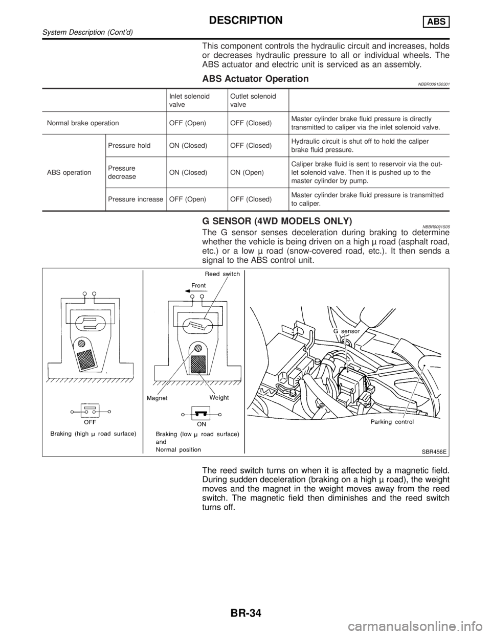
G SENSOR (4WD MODELS ONLY)NBBR0091S05The G sensor senses deceleration during braking to determine
whether the vehicle is being driven on a high road (asphalt road,
etc.) or a low road (snow-covered road, etc.). It then sends a
signal to the ABS control unit.
SBR456E
The reed switch turns on when it is affected by a magnetic field.
During sudden deceleration (braking on a high road), the weight
moves and the magnet in the weight moves away from the reed
switch. The magnetic field then diminishes and the reed switch
turns off.
DESCRIPTIONABS
System Description (Cont'd)
BR-34
Page 432 of 2395

CONSULT-II=NBBR0096CONSULT-II APPLICATION TO ABSNBBR0096S01
ITEMSELF-DIAGNOSTIC
RESULTSDATA MONITOR ACTIVE TEST
Front right wheel sensor´´Ð
Front left wheel sensor´´Ð
Rear right wheel sensor´´Ð
Rear left wheel sensor´´Ð
G switch (G sensor)H´´´
ABS sensor´ÐÐ
Stop lamp switch дÐ
Front right inlet solenoid valve´´´
Front right outlet solenoid valve´´´
Front left inlet solenoid valve´´´
Front left outlet solenoid valve´´´
Rear inlet solenoid valve´´´
Rear outlet solenoid valve´´´
Actuator solenoid valve relay´´Ð
Actuator motor relay
(ABS MOTOR is shown on the Data Monitor
screen.)´´´
ABS warning lamp дÐ
Battery voltage´´Ð
Control unit´ÐÐ
ABS operating signal д´
´: Applicable
Ð: Not applicable
H: 4WD models only
ECU (ABS CONTROL UNIT) PART NUMBER MODENBBR0096S02Ignore the ECU part number displayed in the ECU PART NUMBER MODE. Refer to parts catalog to order
the ECU.
GI
MA
EM
LC
EC
FE
AT
TF
PD
AX
SU
ST
RS
BT
HA
SC
EL
IDX
ON BOARD DIAGNOSTIC SYSTEM DESCRIPTIONABS
CONSULT-II
BR-43
Page 434 of 2395
![INFINITI QX4 2001 Factory User Guide SELF-DIAGNOSTIC RESULTS MODENBBR0097S02
Diagnostic item Diagnostic item is detected when ... Reference Page
FR RH SENSOR*1
[OPEN]ICircuit for front right wheel sensor is open.
(An abnormally high inpu INFINITI QX4 2001 Factory User Guide SELF-DIAGNOSTIC RESULTS MODENBBR0097S02
Diagnostic item Diagnostic item is detected when ... Reference Page
FR RH SENSOR*1
[OPEN]ICircuit for front right wheel sensor is open.
(An abnormally high inpu](/img/42/57027/w960_57027-433.png)
SELF-DIAGNOSTIC RESULTS MODENBBR0097S02
Diagnostic item Diagnostic item is detected when ... Reference Page
FR RH SENSOR*1
[OPEN]ICircuit for front right wheel sensor is open.
(An abnormally high input voltage is entered.)BR-56
FR LH SENSOR*1
[OPEN]ICircuit for front left wheel sensor is open.
(An abnormally high input voltage is entered.)BR-56
RR RH SENSOR*1
[OPEN]ICircuit for rear right sensor is open.
(An abnormally high input voltage is entered.)BR-56
RR LH SENSOR*1
[OPEN]ICircuit for rear left sensor is open.
(An abnormally high input voltage is entered.)BR-56
FR RH SENSOR*1
[SHORT]ICircuit for front right wheel sensor is shorted.
(An abnormally low input voltage is entered.)BR-56
FR LH SENSOR*1
[SHORT]ICircuit for front left wheel sensor is shorted.
(An abnormally low input voltage is entered.)BR-56
RR RH SENSOR*1
[SHORT]ICircuit for rear right sensor is shorted.
(An abnormally low input voltage is entered.)BR-56
RR LH SENSOR*1
[SHORT]ICircuit for rear left sensor is shorted.
(An abnormally low input voltage is entered.)BR-56
ABS SENSOR*1
[ABNORMAL SIGNAL]ITeeth damage on sensor rotor or improper installation of wheel sensor.
(Abnormal wheel sensor signal is entered.)BR-56
FR RH IN ABS SOL
[OPEN, SHORT]ICircuit for front right inlet solenoid valve is open.
(An abnormally low output voltage is entered.)BR-59
FR LH IN ABS SOL
[OPEN, SHORT]ICircuit for front left inlet solenoid valve is open.
(An abnormally low output voltage is entered.)BR-59
FR RH OUT ABS SOL
[OPEN, SHORT]ICircuit for front right outlet solenoid valve is open.
(An abnormally low output voltage is entered.)BR-59
FR LH OUT ABS SOL
[OPEN, SHORT]ICircuit for front left outlet solenoid valve is open.
(An abnormally low output voltage is entered.)BR-59
RR IN ABS SOL
[OPEN, SHORT]ICircuit for rear inlet solenoid valve is shorted.
(An abnormally high output voltage is entered.)BR-59
RR OUT ABS SOL
[OPEN, SHORT]ICircuit for rear out solenoid valve is shorted.
(An abnormally high output voltage is entered.)BR-59
ABS ACTUATOR RELAY
[ABNORMAL]IActuator solenoid valve relay is ON, even if control unit sends off signal.
IActuator solenoid valve relay is OFF, even if control unit sends on signal.BR-59
ABS MOTOR RELAY
[ABNORMAL]ICircuit for ABS motor relay is open or shorted.
ICircuit for actuator motor is open or shorted.
IActuator motor relay is stuck.BR-61
BATTERY VOLT
[VB-LOW]IPower source voltage supplied to ABS control unit is abnormally low.
BR-63
CONTROL UNITIFunction of calculation in ABS control unit has failed. BR-68
G SENSOR*2
[ABNORMAL]IG sensor circuit is open or shorted.
BR-65
*1: If one or more wheels spin on a rough or slippery road for 40 seconds or more, the ABS warning lamp will illuminate. This does not
indicate a malfunction. Only in the case of the short-circuit (Code Nos. 26, 22, 32 and 36), after repair the ABS warning lamp also illu-
minates when the ignition switch is turned ON. In this case, drive the vehicle at speeds greater than 30 km/h (19 MPH) for approxi-
mately 1 minute as specified in ªSELF-DIAGNOSIS PROCEDUREº, BR-41. Check to ensure that the ABS warning lamp goes out while
the vehicle is being driven.
*2: 4WD models onlyGI
MA
EM
LC
EC
FE
AT
TF
PD
AX
SU
ST
RS
BT
HA
SC
EL
IDX
ON BOARD DIAGNOSTIC SYSTEM DESCRIPTIONABS
CONSULT-II Inspection Procedure (Cont'd)
BR-45
Page 437 of 2395

DATA MONITOR MODENBBR0097S05
MONITOR ITEM CONDITION SPECIFICATION
FR RH SENSOR
FR LH SENSOR
RR RH SENSOR
RR LH SENSORDrive vehicle.
(Each wheel is rotating.)Wheel speed signal
(Almost the same speed as speedometer.)
STOP LAMP SW Brake is depressed.Depress the pedal: ON
Release the pedal: OFF
G-SWITCHHVehicle is driven.
Vehicle is stopped.
Brake is applied.During sudden braking while driving on high roads (asphalt
roads, etc.): OFF
While vehicle is stopped or during constant-speed driving: ON
FR RH IN SOL
FR RH OUT SOL
FR LH IN SOL
FR LH OUT SOL
RR IN SOL
RR OUT SOL1. Drive vehicle at speeds
over 30 km/h (19 MPH) for at
least 1 minute.
2. Engine is running.Operating conditions for each solenoid valve are indicated. ABS
is not operating: OFF
MOTOR RELAYABS is not operating: OFF
ABS is operating: ON
ACTUATOR RELAY
Ignition switch is ON or
engine is running.Ignition switch ON (Engine stops): OFF
Engine running: ON
WARNING LAMPABS warning lamp is turned on: ON
ABS warning lamp is turned off: OFF
BATTERY VOLT Power supply voltage for control unit
ABS OPER SIGABS is not operating: OFF
ABS is operating: ON
H: 4WD model only
ACTIVE TEST MODENBBR0097S06
TEST ITEM CONDITION JUDGEMENT
FR RH SOLENOID
FR LH SOLENOID
RR SOLENOID
Engine is running.Brake fluid pressure control operation
IN SOL OUT SOL
UP (Increase): OFF OFF
KEEP (Hold): ON OFF
DOWN (Decrease): ON ON
ABS MOTORABS actuator motor
ON: Motor runs (ABS motor relay ON)
OFF: Motor stops (ABS motor relay OFF)
ABS OPER SIGIgnition switch is ON or
engine is running.ON: Set ABS OPER SIG ªONº (ABS is operating.)
OFF: Set ABS OPER SIG ªOFFº (ABS is not operating.)
G SWITCHHIgnition switch is ON.G SWITCH (G SENSOR)
ON: Set G SWITCH MONITOR ªONº (G switch circuit is
closed.)
OFF: Set G SWITCH MONITOR ªOFFº (G switch circuit is
open.)
H: 4WD models only
NOTE:
Active test will automatically stop ten seconds after the test starts. (TEST IS STOPPED monitor shows ON.)
ON BOARD DIAGNOSTIC SYSTEM DESCRIPTIONABS
CONSULT-II Inspection Procedure (Cont'd)
BR-48
Page 444 of 2395

*3: The trouble code ª61º can sometimes appear when the ABS motor is not properly grounded. If it appears, be sure to check the con-
dition of the ABS motor ground circuit connection.
*4: 4WD models only
GI
MA
EM
LC
EC
FE
AT
TF
PD
AX
SU
ST
RS
BT
HA
SC
EL
IDX
TROUBLE DIAGNOSIS Ð GENERAL DESCRIPTIONABS
Malfunction Code/Symptom Chart (Cont'd)
BR-55
Page 456 of 2395

SBR844DF
ELECTRICAL COMPONENT INSPECTION=NBBR0115G Sensor (4WD models only)NBBR0115S01CAUTION:
The G sensor is easily damaged if it sustains an impact. Be
careful not to drop or bump it.
1. Measure resistance between terminals 2 and 51 of G sensor
unit connector.
G sensor conditionResistance between ter-
minals 2 and 51G sensor switch condi-
tion
Installed in vehicle 1.4 - 1.6 kWªONº
Tilted as shown in figure 4.7 - 5.5 kWªOFFº
2. Measure resistance between terminals 1 and 17 of the G sen-
sor unit connector.
Resistance: 70 - 124W
GI
MA
EM
LC
EC
FE
AT
TF
PD
AX
SU
ST
RS
BT
HA
SC
EL
IDX
TROUBLE DIAGNOSES FOR SELF-DIAGNOSTIC ITEMSABS
G Sensor and Circuit (Cont'd)
BR-67