4wd INFINITI QX4 2001 Factory Service Manual
[x] Cancel search | Manufacturer: INFINITI, Model Year: 2001, Model line: QX4, Model: INFINITI QX4 2001Pages: 2395, PDF Size: 43.2 MB
Page 279 of 2395

SAT360IA
Revolution Sensor ReplacementNBAT0210Ð 4WD MODEL ÐNBAT0210S011. Remove rear engine mounting member from side member
while supporting A/T with transfer case with jack. Tighten rear
engine mounting member to the specified torque. Refer to
EM-59, ªRear Engine Mountingº.
2. Lower A/T with transfer case as much as possible.
3. Remove revolution sensor from A/T.
4. Reinstall any part removed.
IAlways use new sealing parts.
SAT661I
Ð 2WD MODEL ÐNBAT0210S02IRemove revolution sensor from A/T.
IAlways use new sealing parts.
SAT136K
Turbine Revolution Sensor ReplacementNBAT02311. Remove A/T assembly, Refer to ªRemovalº, AT-277.
2. Remove turbine revolution sensor from A/T assembly upper
side.
3. Reinstall any part removed.
IAlways use new sealing parts.
SAT035E
Rear Oil Seal ReplacementNBAT0211Ð 4WD MODEL ÐNBAT0211S011. Remove transfer case from vehicle. Refer to TF-119, ªRemovalº.
2. Remove rear oil seal.
IDo not remove oil seal unless it is to be replaced.
3. Install rear oil seal.
IApply ATF before installing.
4. Reinstall any part removed.
ON-VEHICLE SERVICE
Revolution Sensor Replacement
AT-274
Page 280 of 2395

SAT544J
SAT546J
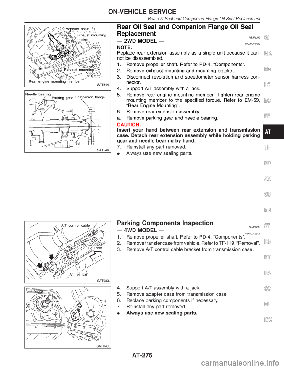
Rear Oil Seal and Companion Flange Oil Seal
Replacement
NBAT0212Ð 2WD MODEL ÐNBAT0212S01NOTE:
Replace rear extension assembly as a single unit because it can-
not be disassembled.
1. Remove propeller shaft. Refer to PD-4, ªComponentsº.
2. Remove exhaust mounting and mounting bracket.
3. Disconnect revolution and speedometer sensor harness con-
nector.
4. Support A/T assembly with a jack.
5. Remove rear engine mounting member. Tighten rear engine
mounting member to the specified torque. Refer to EM-59,
ªRear Engine Mountingº.
6. Remove rear extension assembly.
a. Remove parking gear and needle bearing.
CAUTION:
Insert your hand between rear extension and transmission
case. Detach rear extension assembly while holding parking
gear and needle bearing by hand.
7. Reinstall any part removed.
IAlways use new sealing parts.
SAT083J
Parking Components InspectionNBAT0213Ð 4WD MODEL ÐNBAT0213S011. Remove propeller shaft. Refer to PD-4, ªComponentsº.
2. Remove transfer case from vehicle. Refer to TF-119, ªRemovalº.
3. Remove A/T control cable bracket from transmission case.
SAT078B
4. Support A/T assembly with a jack.
5. Remove adapter case from transmission case.
6. Replace parking components if necessary.
7. Reinstall any part removed.
IAlways use new sealing parts.
GI
MA
EM
LC
EC
FE
TF
PD
AX
SU
BR
ST
RS
BT
HA
SC
EL
IDX
ON-VEHICLE SERVICE
Rear Oil Seal and Companion Flange Oil Seal Replacement
AT-275
Page 282 of 2395

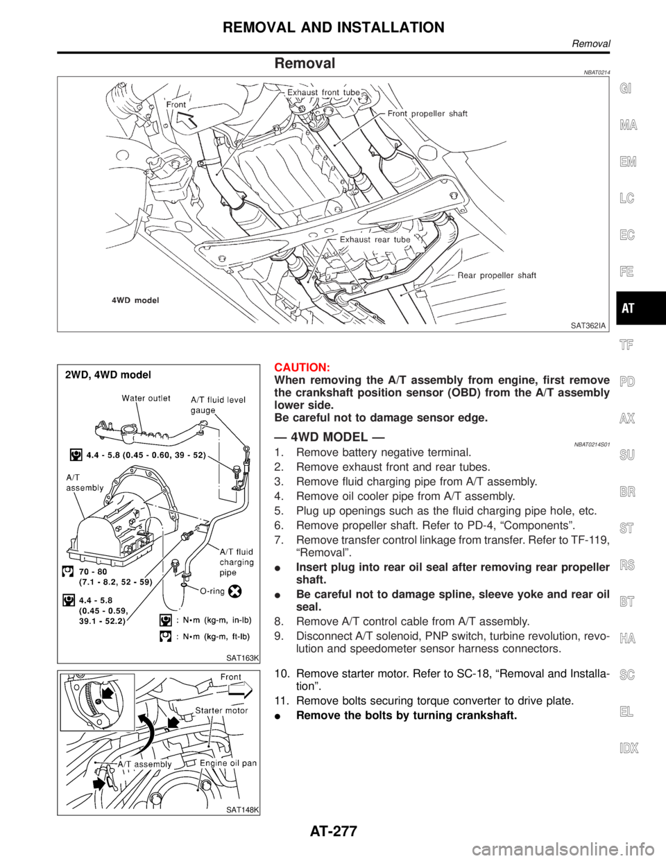
RemovalNBAT0214
SAT362IA
SAT163K
CAUTION:
When removing the A/T assembly from engine, first remove
the crankshaft position sensor (OBD) from the A/T assembly
lower side.
Be careful not to damage sensor edge.
Ð 4WD MODEL ÐNBAT0214S011. Remove battery negative terminal.
2. Remove exhaust front and rear tubes.
3. Remove fluid charging pipe from A/T assembly.
4. Remove oil cooler pipe from A/T assembly.
5. Plug up openings such as the fluid charging pipe hole, etc.
6. Remove propeller shaft. Refer to PD-4, ªComponentsº.
7. Remove transfer control linkage from transfer. Refer to TF-119,
ªRemovalº.
IInsert plug into rear oil seal after removing rear propeller
shaft.
IBe careful not to damage spline, sleeve yoke and rear oil
seal.
8. Remove A/T control cable from A/T assembly.
9. Disconnect A/T solenoid, PNP switch, turbine revolution, revo-
lution and speedometer sensor harness connectors.
SAT148K
10. Remove starter motor. Refer to SC-18, ªRemoval and Installa-
tionº.
11. Remove bolts securing torque converter to drive plate.
IRemove the bolts by turning crankshaft.
GI
MA
EM
LC
EC
FE
TF
PD
AX
SU
BR
ST
RS
BT
HA
SC
EL
IDX
REMOVAL AND INSTALLATION
Removal
AT-277
Page 297 of 2395

SAT755I
20. Remove adapter case (4WD model only).
a. Remove adapter case from transmission case.
b. Remove adapter case gasket from transmission case.
SAT756I
c. Remove oil seal from adapter case.
IBe careful not to scratch adapter case.
IDo not remove oil seal unless it is to be replaced.
SAT556J
21. Remove revolution sensor from rear extension or adapter
case.
a. Remove O-ring from revolution sensor.
SAT960A
22. Remove output shaft and parking gear (4WD model only).
a. Remove rear snap ring from output shaft.
SAT957A
b. Slowly push output shaft all the way forward.
IDo not use excessive force.
c. Remove snap ring from output shaft.
DISASSEMBLY
AT-292
Page 328 of 2395

SAT867A
IAlign notch in forward clutch piston with groove in for-
ward clutch drum.
SAT868A
b) Install overrun clutch by turning it slowly and evenly.
IApply ATF to inner surface of forward clutch piston.
SAT869A
IMeasurement of clearance between retaining plate and snap
ring of overrun clutch
Specified clearance:
Standard
1.0 - 1.4 mm (0.039 - 0.055 in)
Allowable limit
2.0 mm (0.079 in)
Retaining plate:
Refer to SDS, AT-359.
SAT870A
IMeasurement of clearance between retaining plate and snap
ring of forward clutch
Specified clearance:
Standard
0.35 - 0.75 mm (0.0138 - 0.0295 in)
Allowable limit
Model 4EX16 (2WD)
2.15 mm (0.0846 in)
Model 4EX17, 4EX23 (4WD)
2.35 mm (0.0925 in)
Retaining plate:
Refer to SDS, AT-359.
GI
MA
EM
LC
EC
FE
TF
PD
AX
SU
BR
ST
RS
BT
HA
SC
EL
IDX
REPAIR FOR COMPONENT PARTS
Forward and Overrun Clutches (Cont'd)
AT-323
Page 330 of 2395

SAT382I
3. Remove low one-way clutch inner race, spring retainer and
return spring from transmission case.
4. Remove seal rings from low one-way clutch inner race.
5. Remove needle bearing from low one-way clutch inner race.
SAT876A
6. Remove low and reverse brake piston using compressed air.
7. Remove oil seal and D-ring from piston.
INSPECTIONNBAT0138Low and Reverse Brake Snap Ring and Spring RetainerNBAT0138S01ICheck for deformation, or damage.
SAT829A
Low and Reverse Brake Return SpringsNBAT0138S02ICheck for deformation or damage. Also measure free length
and outside diameter.
Inspection standard:
Refer to SDS, AT-357.
SAT845A
Low and Reverse Brake Drive PlatesNBAT0138S03ICheck facing for burns, cracks or damage.
IMeasure thickness of facing.
Thickness of drive plate:
Standard value
Model 4EX16 (2WD)
1.90 - 2.05 mm (0.075 - 0.081 in)
Model 4EX17, 4EX23 (4WD)
1.52 - 1.67 mm (0.0598 - 0.0657 in)
Wear limit
GI
MA
EM
LC
EC
FE
TF
PD
AX
SU
BR
ST
RS
BT
HA
SC
EL
IDX
REPAIR FOR COMPONENT PARTS
Low & Reverse Brake (Cont'd)
AT-325
Page 348 of 2395

SAT952A
j. Install needle bearing onto rear internal gear.
IApply petroleum jelly to needle bearing.
SAT953A
k. Install bearing race onto rear of front internal gear.
IApply petroleum jelly to bearing race.
ISecurely engage pawls of bearing race with holes in front
internal gear.
SAT954A
l. Install front internal gear on transmission case.
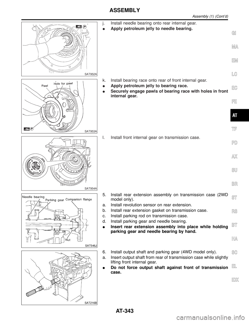
SAT546J
5. Install rear extension assembly on transmission case (2WD
model only).
a. Install revolution sensor on rear extension.
b. Install rear extension gasket on transmission case.
c. Install parking rod on transmission case.
d. Install parking gear and needle bearing.
IInsert rear extension assembly into place while holding
parking gear and needle bearing by hand.
SAT216B
6. Install output shaft and parking gear (4WD model only).
a. Insert output shaft from rear of transmission case while slightly
lifting front internal gear.
IDo not force output shaft against front of transmission
case.
GI
MA
EM
LC
EC
FE
TF
PD
AX
SU
BR
ST
RS
BT
HA
SC
EL
IDX
ASSEMBLY
Assembly (1) (Cont'd)
AT-343
Page 349 of 2395

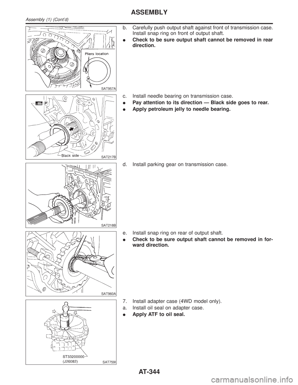
SAT957A
b. Carefully push output shaft against front of transmission case.
Install snap ring on front of output shaft.
ICheck to be sure output shaft cannot be removed in rear
direction.
SAT217B
c. Install needle bearing on transmission case.
IPay attention to its direction Ð Black side goes to rear.
IApply petroleum jelly to needle bearing.
SAT218B
d. Install parking gear on transmission case.
SAT960A
e. Install snap ring on rear of output shaft.
ICheck to be sure output shaft cannot be removed in for-
ward direction.
SAT759I
7. Install adapter case (4WD model only).
a. Install oil seal on adapter case.
IApply ATF to oil seal.
ASSEMBLY
Assembly (1) (Cont'd)
AT-344
Page 361 of 2395

General SpecificationsNBAT0160
Applied modelVQ35DE engine
2WD 4WD
Automatic transmission model RE4R01A
Transmission model code number 4EX16 4EX17
Stall torque ratio2.0:1
Transmission gear ratio1st 2.785
2nd 1.545
Top 1.000
OD 0.694
Reverse 2.272
Recommended fluidNissan Matic ªDº (Continental U.S. and Alaska) or Genuine Nissan Automatic Trans-
mission Fluid (Canada)*1
Fluid capacity8.5(9 US qt, 7-1/2 Imp qt)
*1: Refer to MA-11, ªFluids and Lubricantsº.
Shift ScheduleNBAT0178VEHICLE SPEED WHEN SHIFTING GEARS THROTTLE POSITIONNBAT0178S01
Throttle positionVehicle speed km/h (MPH)
D
1,D2D2,D3D3,D4D4,D3D3,D2D2,D112,11
Full throttle55-59
(34 - 37)105 - 113
(65 - 70)174 - 184
(108 - 114)170 - 180
(106 - 112)102 - 110
(63 - 68)43-47
(27 - 29)43-47
(27 - 29)
Half throttle37-41
(23 - 25)71-79
(44 - 49)129 - 139
(80 - 86)81-91
(50 - 57)33-41
(21 - 25)12-16
(7 - 10)43-47
(27 - 29)
VEHICLE SPEED WHEN PERFORMING AND RELEASING LOCK-UPNBAT0178S02
Throttle positionOverdrive control switch [Shift posi-
tion]Vehicle speed km/h (MPH)
Lock-up ªONº Lock-up ªOFFº
Full throttleON [D
4] 174 - 184 (108 - 114) 170 - 180 (106 - 112)
OFF [D
3] 104 - 114 (65 - 71) 101 - 111 (63 - 69)
Half throttleON [D
4] 151 - 161 (94 - 100) 106 - 116 (66 - 72)
OFF [D
3] 85-95(53-59) 82-92(51-57)
Stall RevolutionNBAT0163
Stall revolution rpm2,440 - 2,640
Line PressureNBAT0164
Engine speed
rpmLine pressure kPa (kg/cm2, psi)
D, 2 and 1 positions R position
Idle 422 - 461 (4.3 - 4.7, 61 - 67) 667 - 706 (6.8 - 7.2, 97 - 102)
Stall 1,020 - 1,098 (10.4 - 11.2, 148 - 159) 1,422 - 1,500 (14.5 - 15.3, 206 - 218)
SERVICE DATA AND SPECIFICATIONS (SDS)
General Specifications
AT-356
Page 390 of 2395

BRAKE SYSTEM
SECTION
BR
CONTENTS
PRECAUTIONS...............................................................3
Supplemental Restraint System (SRS)²AIR
BAG²and²SEAT BELT PRE-TENSIONER²...............3
Precautions for Brake System .....................................3
Wiring Diagrams and Trouble Diagnoses....................4
PREPARATION...............................................................5
Special Service Tools ..................................................5
Commercial Service Tools ...........................................5
NOISE, VIBRATION AND HARSHNESS (NVH)
TROUBLESHOOTING.....................................................6
NVH Troubleshooting Chart.........................................6
ON-VEHICLE SERVICE..................................................7
Checking Brake Fluid Level.........................................7
Checking Brake Line ...................................................7
Changing Brake Fluid ..................................................7
Bleeding Brake System ...............................................8
BRAKE HYDRAULIC LINE.............................................9
Hydraulic Circuit...........................................................9
Removal .....................................................................10
Inspection...................................................................10
Installation ..................................................................10
PROPORTIONING VALVE (2WD)................................ 11
Inspection................................................................... 11
Removal and Installation (Built-in type)..................... 11
LOAD SENSING VALVE (4WD)...................................12
Inspection...................................................................12
Removal and Installation ...........................................12
BRAKE PEDAL AND BRACKET..................................14
Removal and Installation ...........................................14
Inspection...................................................................14
Adjustment .................................................................14
MASTER CYLINDER.....................................................16
Removal .....................................................................16
Disassembly...............................................................16
Inspection...................................................................17
Assembly ...................................................................17
Installation ..................................................................18
BRAKE BOOSTER........................................................19
On-vehicle Service.....................................................19OPERATING CHECK...............................................19
AIRTIGHT CHECK...................................................19
Removal .....................................................................19
Inspection...................................................................19
OUTPUT ROD LENGTH CHECK..............................19
Installation ..................................................................20
VACUUM PIPING...........................................................21
Vacuum Hose ............................................................21
Removal and Installation ...........................................21
Inspection...................................................................21
HOSES AND CONNECTORS...................................21
CHECK VALVE........................................................21
FRONT DISC BRAKE...................................................22
Components...............................................................22
Pad Replacement ......................................................22
Removal .....................................................................23
Disassembly...............................................................24
Inspection...................................................................24
CALIPER.................................................................24
ROTOR...................................................................24
Assembly ...................................................................25
Installation ..................................................................25
Brake Burnishing Procedure......................................25
REAR DRUM BRAKE...................................................26
Components...............................................................26
Removal .....................................................................26
Inspection...................................................................27
WHEEL CYLINDER..................................................27
Wheel Cylinder Overhaul...........................................28
Inspection...................................................................28
DRUM.....................................................................28
LINING....................................................................28
Installation ..................................................................28
PARKING BRAKE CONTROL......................................30
Components...............................................................30
Removal and Installation ...........................................30
Inspection...................................................................30
Adjustment .................................................................31
GI
MA
EM
LC
EC
FE
AT
TF
PD
AX
SU
ST
RS
BT
HA
SC
EL
IDX