window INFINITI QX4 2001 Factory User Guide
[x] Cancel search | Manufacturer: INFINITI, Model Year: 2001, Model line: QX4, Model: INFINITI QX4 2001Pages: 2395, PDF Size: 43.2 MB
Page 1098 of 2395

SEF355X
Overall Function CheckNBEC0336Use this procedure to check the overall monitoring function of the
EVAP control system purge flow monitoring. During this check, a
1st trip DTC might not be confirmed.
WITH GSTNBEC0336S011) Lift up drive wheels.
2) Start engine (TCS switch ªOFFº) and warm it up to normal
operating temperature.
3) Turn ignition switch ªOFFº, wait at least 10 seconds.
4) Start engine and wait at least 70 seconds.
5) Set voltmeter probes to ECM terminals 84 (EVAP control sys-
tem pressure sensor signal) and ground.
6) Check EVAP control system pressure sensor value at idle
speed and note it.
7) Establish and maintain the following conditions for at least 1
minute.
Air conditioner switch ON
Steering wheel Fully turned
Headlamp switch ON
Rear window defogger switch ON
Engine speed Approx. 3,000 rpm
Gear position Any position other than ªPº, ªNº or ªRº
8) Verify that EVAP control system pressure sensor value stays
0.1V less than the value at idle speed (measured at step 6) for
at least 1 second.
9) If NG, go to ªDiagnostic Procedureº, EC-564.
GI
MA
EM
LC
FE
AT
TF
PD
AX
SU
BR
ST
RS
BT
HA
SC
EL
IDX
DTC P1447 EVAPORATIVE EMISSION (EVAP) CONTROL SYSTEM PURGE
FLOW MONITORING
Overall Function Check
EC-563
Page 1178 of 2395

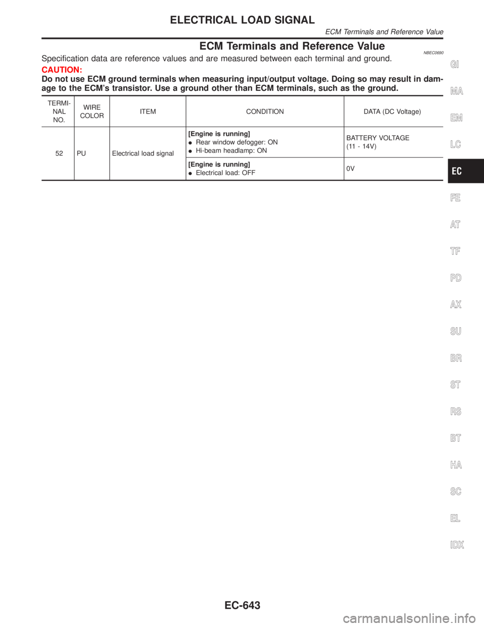
ECM Terminals and Reference ValueNBEC0690Specification data are reference values and are measured between each terminal and ground.
CAUTION:
Do not use ECM ground terminals when measuring input/output voltage. Doing so may result in dam-
age to the ECM's transistor. Use a ground other than ECM terminals, such as the ground.
TERMI-
NAL
NO.WIRE
COLORITEM CONDITION DATA (DC Voltage)
52 PU Electrical load signal[Engine is running]
IRear window defogger: ON
IHi-beam headlamp: ONBATTERY VOLTAGE
(11 - 14V)
[Engine is running]
IElectrical load: OFF0V
GI
MA
EM
LC
FE
AT
TF
PD
AX
SU
BR
ST
RS
BT
HA
SC
EL
IDX
ELECTRICAL LOAD SIGNAL
ECM Terminals and Reference Value
EC-643
Page 1180 of 2395

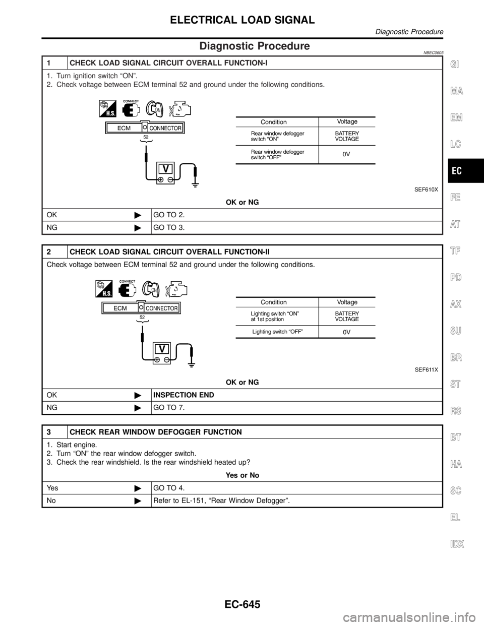
Diagnostic ProcedureNBEC0605
1 CHECK LOAD SIGNAL CIRCUIT OVERALL FUNCTION-I
1. Turn ignition switch ªONº.
2. Check voltage between ECM terminal 52 and ground under the following conditions.
SEF610X
OK or NG
OK©GO TO 2.
NG©GO TO 3.
2 CHECK LOAD SIGNAL CIRCUIT OVERALL FUNCTION-II
Check voltage between ECM terminal 52 and ground under the following conditions.
SEF611X
OK or NG
OK©INSPECTION END
NG©GO TO 7.
3 CHECK REAR WINDOW DEFOGGER FUNCTION
1. Start engine.
2. Turn ªONº the rear window defogger switch.
3. Check the rear windshield. Is the rear windshield heated up?
YesorNo
Ye s©GO TO 4.
No©Refer to EL-151, ªRear Window Defoggerº.
GI
MA
EM
LC
FE
AT
TF
PD
AX
SU
BR
ST
RS
BT
HA
SC
EL
IDX
ELECTRICAL LOAD SIGNAL
Diagnostic Procedure
EC-645
Page 1181 of 2395

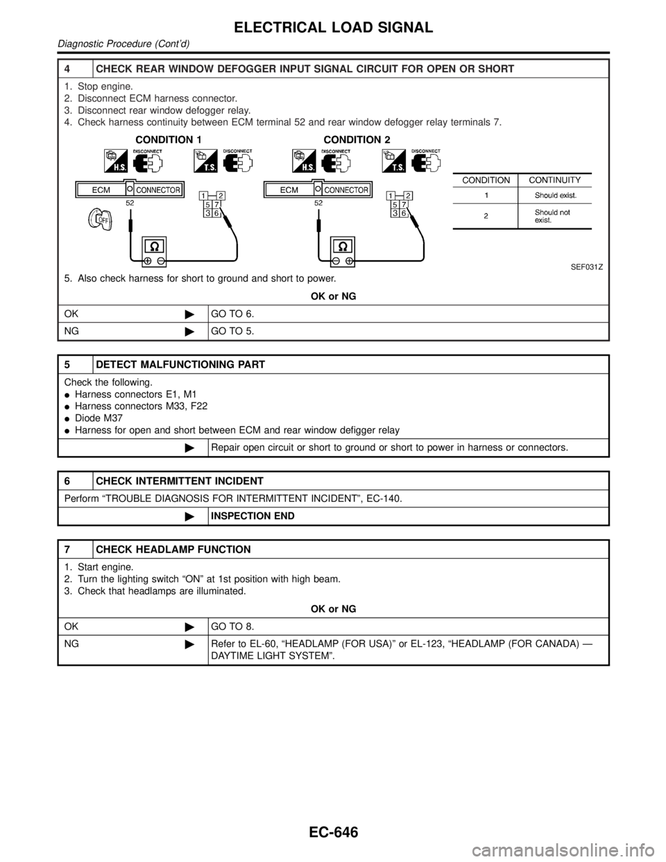
4 CHECK REAR WINDOW DEFOGGER INPUT SIGNAL CIRCUIT FOR OPEN OR SHORT
1. Stop engine.
2. Disconnect ECM harness connector.
3. Disconnect rear window defogger relay.
4. Check harness continuity between ECM terminal 52 and rear window defogger relay terminals 7.
SEF031Z
5. Also check harness for short to ground and short to power.
OK or NG
OK©GO TO 6.
NG©GO TO 5.
5 DETECT MALFUNCTIONING PART
Check the following.
IHarness connectors E1, M1
IHarness connectors M33, F22
IDiode M37
IHarness for open and short between ECM and rear window defigger relay
©Repair open circuit or short to ground or short to power in harness or connectors.
6 CHECK INTERMITTENT INCIDENT
Perform ªTROUBLE DIAGNOSIS FOR INTERMITTENT INCIDENTº, EC-140.
©INSPECTION END
7 CHECK HEADLAMP FUNCTION
1. Start engine.
2. Turn the lighting switch ªONº at 1st position with high beam.
3. Check that headlamps are illuminated.
OK or NG
OK©GO TO 8.
NG©Refer to EL-60, ªHEADLAMP (FOR USA)º or EL-123, ªHEADLAMP (FOR CANADA) Ð
DAYTIME LIGHT SYSTEMº.
ELECTRICAL LOAD SIGNAL
Diagnostic Procedure (Cont'd)
EC-646
Page 1184 of 2395

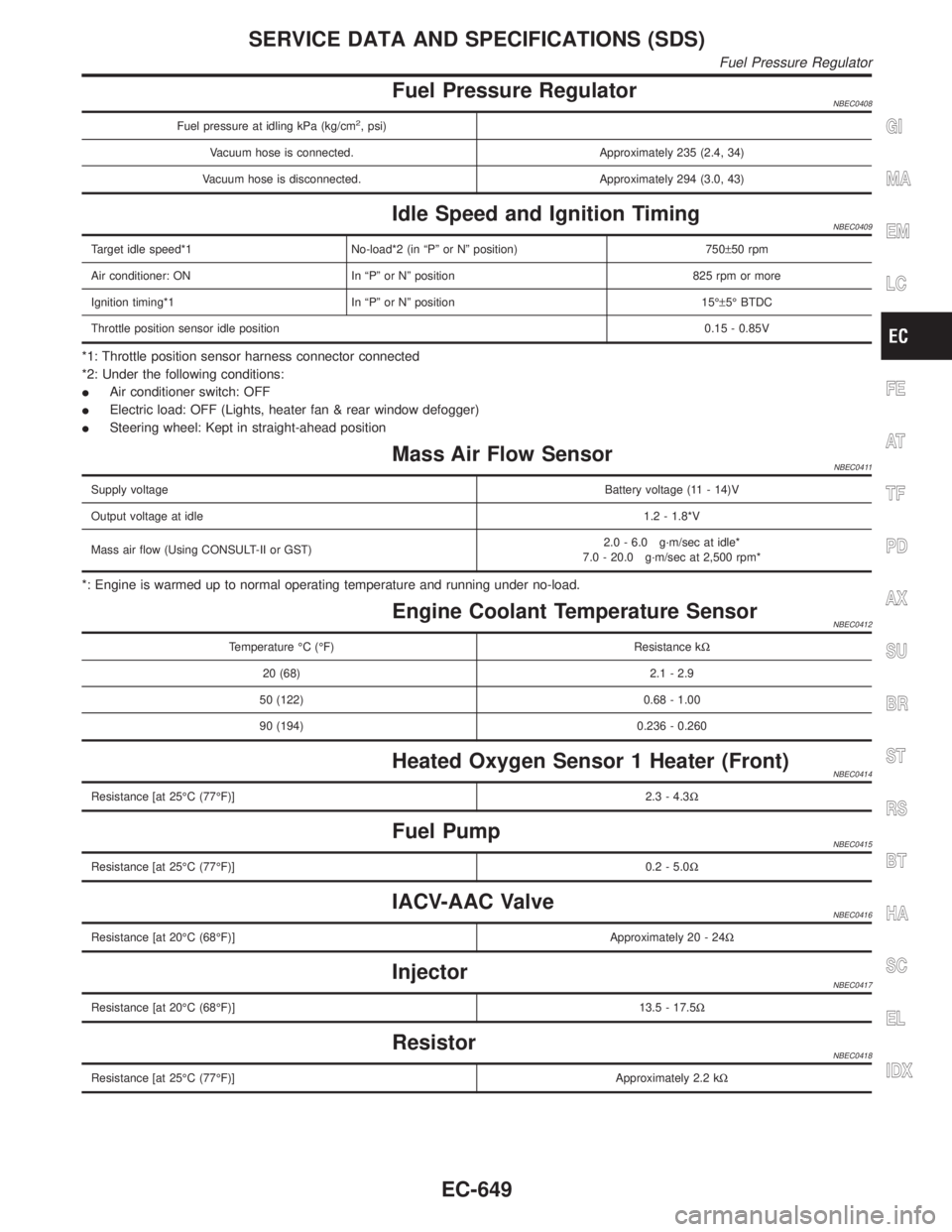
Fuel Pressure RegulatorNBEC0408
Fuel pressure at idling kPa (kg/cm2, psi)
Vacuum hose is connected. Approximately 235 (2.4, 34)
Vacuum hose is disconnected. Approximately 294 (3.0, 43)
Idle Speed and Ignition TimingNBEC0409
Target idle speed*1 No-load*2 (in ªPº or Nº position) 750±50 rpm
Air conditioner: ON In ªPº or Nº position 825 rpm or more
Ignition timing*1 In ªPº or Nº position 15ɱ5É BTDC
Throttle position sensor idle position0.15 - 0.85V
*1: Throttle position sensor harness connector connected
*2: Under the following conditions:
IAir conditioner switch: OFF
IElectric load: OFF (Lights, heater fan & rear window defogger)
ISteering wheel: Kept in straight-ahead position
Mass Air Flow SensorNBEC0411
Supply voltageBattery voltage (11 - 14)V
Output voltage at idle1.2 - 1.8*V
Mass air flow (Using CONSULT-II or GST)2.0 - 6.0 g´m/sec at idle*
7.0 - 20.0 g´m/sec at 2,500 rpm*
*: Engine is warmed up to normal operating temperature and running under no-load.
Engine Coolant Temperature SensorNBEC0412
Temperature ÉC (ÉF) Resistance kW
20 (68) 2.1 - 2.9
50 (122) 0.68 - 1.00
90 (194) 0.236 - 0.260
Heated Oxygen Sensor 1 Heater (Front)NBEC0414
Resistance [at 25ÉC (77ÉF)]2.3 - 4.3W
Fuel PumpNBEC0415
Resistance [at 25ÉC (77ÉF)]0.2 - 5.0W
IACV-AAC ValveNBEC0416
Resistance [at 20ÉC (68ÉF)]Approximately 20 - 24W
InjectorNBEC0417
Resistance [at 20ÉC (68ÉF)]13.5 - 17.5W
ResistorNBEC0418
Resistance [at 25ÉC (77ÉF)]Approximately 2.2 kW
GI
MA
EM
LC
FE
AT
TF
PD
AX
SU
BR
ST
RS
BT
HA
SC
EL
IDX
SERVICE DATA AND SPECIFICATIONS (SDS)
Fuel Pressure Regulator
EC-649
Page 1187 of 2395

Electrical Components Inspection ...........................108
COMPASS AND THERMOMETER............................. 110
System Description .................................................. 110
Wiring Diagram - COMPAS -................................... 111
Trouble Diagnoses................................................... 112
Calibration Procedure for Compass ........................ 113
WARNING LAMPS...................................................... 114
Schematic ................................................................ 114
Wiring Diagram - WARN - ....................................... 115
Fuel Warning Lamp Sensor Check .........................122
Electrical Components Inspection ...........................122
A/T INDICATOR...........................................................123
Wiring Diagram - AT/IND -.......................................123
WARNING CHIME.......................................................125
Component Parts and Harness Connector
Location ...................................................................125
System Description ..................................................125
Wiring Diagram - CHIME - ......................................127
Trouble Diagnoses...................................................129
FRONT WIPER AND WASHER..................................136
System Description ..................................................136
Wiring Diagram - WIPER - ......................................138
Removal and Installation .........................................139
Washer Nozzle Adjustment .....................................140
Washer Tube Layout ...............................................140
REAR WIPER AND WASHER....................................141
System Description ..................................................141
Wiring Diagram - WIP/R -........................................143
Trouble Diagnoses...................................................145
Removal and Installation .........................................145
Washer Nozzle Adjustment .....................................146
Washer Tube Layout ...............................................146
Check Valve .............................................................146
HORN...........................................................................147
Wiring Diagram - HORN - .......................................147
CIGARETTE LIGHTER................................................148
Wiring Diagram - CIGAR -.......................................148
CLOCK.........................................................................150
Wiring Diagram - CLOCK -......................................150
REAR WINDOW DEFOGGER.....................................151
Component Parts and Harness Connector
Location ...................................................................151
System Description ..................................................151
Wiring Diagram - DEF - ...........................................153
Trouble Diagnoses...................................................155
Electrical Components Inspection ...........................157
Filament Check ........................................................157
Filament Repair .......................................................158
AUDIO..........................................................................160
System Description ..................................................160
Schematic ................................................................161
Wiring Diagram - AUDIO - .......................................162Trouble Diagnoses...................................................166
Inspection.................................................................167
Wiring Diagram - REMOTE -...................................168
AUDIO ANTENNA.......................................................169
System Description ..................................................169
Wiring Diagram - P/ANT - .......................................170
Trouble Diagnoses...................................................171
Location of Antenna .................................................171
Antenna Rod Replacement .....................................171
POWER SUNROOF.....................................................173
System Description ..................................................173
Wiring Diagram - SROOF - .....................................174
Trouble Diagnoses...................................................176
DOOR MIRROR...........................................................177
Wiring Diagram - MIRROR - ...................................177
GLASS HATCH OPENER...........................................178
System Description ..................................................178
Wiring Diagram - TLID - ..........................................179
FUEL FILLER LID OPENER.......................................180
Wiring Diagram - F/LID - .........................................180
POWER SEAT.............................................................181
Wiring Diagram - SEAT - .........................................181
HEATED SEAT............................................................183
Wiring Diagram - HSEAT - ......................................183
Seatback Heating Unit .............................................185
AUTOMATIC DRIVE POSITIONER............................186
Component Parts and Harness Connector
Location ...................................................................186
System Description ..................................................187
Schematic ................................................................190
Wiring Diagram - AUT/DP - .....................................191
On Board Diagnosis ................................................196
Trouble Diagnoses...................................................198
AUTOMATIC SPEED CONTROL DEVICE (ASCD)...221
Component Parts and Harness Connector
Location ...................................................................221
System Description ..................................................222
Schematic ................................................................224
Wiring Diagram - ASCD - ........................................225
Fail-safe System ......................................................229
Trouble Diagnoses...................................................230
Electrical Component Inspection .............................239
ASCD Wire Adjustment ...........................................240
POWER WINDOW.......................................................241
System Description ..................................................241
Schematic ................................................................244
Wiring Diagram - WINDOW - ..................................245
Trouble Diagnoses...................................................250
POWER DOOR LOCK.................................................254
Component Parts and Harness Connector
Location ...................................................................254
System Description ..................................................254
CONTENTS(Cont'd)
EL-2
Page 1265 of 2395

System DescriptionNBEL0035The illumination lamp operation is controlled by the lighting switch which is built into the combination switch
and headlamp battery saver control unit. The battery saver system is controlled by the headlamp battery saver
control unit and smart entrance control unit.
Power is supplied at all times
Ito tail lamp relay terminals 2 and 3
Ithrough 10A fuse (No. 61, located in the fuse and fusible link box), and
Ito headlamp battery saver control unit terminal 7, and
Ito smart entrance control unit terminal 10
Ithrough 7.5A fuse [No. 24, located in the fuse block (J/B)].
When ignition switch is in ON or START position, power is supplied
Ito headlamp battery saver control unit terminal 1
Ithrough 10A fuse [No. 16, located in the fuse block (J/B)], and
Ito headlamp battery saver control unit terminal 10, and
Ito smart entrance control unit terminal 33
Ithrough 7.5A fuse [No. 11, located in the fuse block (J/B)].
Ground is supplied to headlamp battery saver control unit terminals 4 and 11.
LIGHTING OPERATION BY LIGHTING SWITCHNBEL0035S01When lighting switch is 1ST (or 2ND) position, ground is supplied
Ito tail lamp relay terminal 1 from headlamp battery saver control unit terminals 6 and 14
Ithrough headlamp battery saver control unit terminals 5 and 13, and
Ithrough body grounds E13 and E41.
Tail lamp relay is then energized and illumination lamps illuminate.
The lighting switch must be in the 1ST or 2ND position for illumination.
LIGHTING OPERATION BY AUTO LIGHT CONTROL SYSTEMNBEL0035S03When auto light operation is operated, ground is supplied
Ito tail lamp relay terminal 1 from headlamp battery saver control unit terminals 6 and 14
Ithrough headlamp battery saver control unit terminals 5 and 13, and
Ithrough auto light control unit terminal 7.
Tail lamp relay is then energized and the illumination lamps illuminate.
The illumination control switch that controls the amount of current to the illumination system. As the amount
of current increases, the illumination becomes brighter.
The following chart shows the power and ground connector terminals for the components included in the illu-
mination system.
Component Connector No. Power terminal Ground terminal
Illumination control switch M19 1 3
4WD shift switch M141 7 8
Ashtray M54 1 2
A/T indicator B59 3 4
Cigarette lighter M57 3 4
Audio unit M48 8 7
Compass and thermometer R4 5 2
Hazard switch M35 7 8
Rear window defogger switch M36 5 6
Headlamp aiming switch M16 3 4
Power window main switch D6 16 18
Front power window switch RH D36 10 17
ILLUMINATION
System Description
EL-80
Page 1336 of 2395

Component Parts and Harness Connector
Location
NBEL0072
SEL465X
System DescriptionNBEL0073The rear window defogger system is controlled by the smart entrance control unit. The rear window defogger
operates only for approximately 15 minutes.
Power is supplied at all times
Ito rear window defogger relay terminal 3
Ithrough 20A fuse (No. 56, located in the fuse and fusible link box) and
Ito rear window defogger relay terminal 6
Ithrough 20A fuse (No. 57, located in the fuse and fusible link box)
Ito smart entrance control unit terminal 10
Ithrough 7.5A [No. 24, located in fuse block (J/B)]
With the ignition switch in the ON or START position, power is supplied
Ithrough 7.5A fuse [No. 11, located in the fuse block (J/B)]
Ito the rear window defogger relay terminal 1, and
Ito smart entrance control unit terminal 33.
Ground is supplied
Ito terminal 1 of the rear window defogger switch
Ithrough body grounds M4, M66 and M147(with navigation system),
Ito terminal 32 of the A/C auto amp.
Ithrough body grounds M4, M66 and M147 (without navigation system), or
Ito smart entrance control unit terminal 16
Ithrough body grounds M77 and M111.
GI
MA
EM
LC
EC
FE
AT
TF
PD
AX
SU
BR
ST
RS
BT
HA
SC
IDX
REAR WINDOW DEFOGGER
Component Parts and Harness Connector Location
EL-151
Page 1337 of 2395

When the rear window defogger switch is turned ON, ground is supplied
Ithrough terminal 2 of the rear window defogger switch (with navigation system), or
Ithrough terminal 31 of A/C auto amp. (without navigation system)
Ito smart entrance control unit terminal 39.
Terminal 2 of the smart entrance control unit then supplies ground to the rear window defogger relay termi-
nal 2.
With power and ground supplied, the rear window defogger relay is energized.
Power is supplied
Ithrough terminals 5 and 7 of the rear window defogger relay
Ito the rear window defogger.
The rear window defogger has an independent ground.
With power and ground supplied, the rear window defogger filaments heat and defog the rear window.
When the system is activated, the rear window defogger indicator illuminates in the rear window defogger
switch.
Power is supplied
Ito terminal 3 of the rear window defogger switch (with navigation system), or
Ito terminal 30 of the A/C auto amp. (without navigation system)
Ifrom terminal 7 of the rear window defogger relay.
Terminal 4 of the rear window defogger switch (with navigation system) or terminal 32 of the A/C auto amp.
(without navigation system), is grounded through body grounds M4, M66 and M147.
REAR WINDOW DEFOGGER
System Description (Cont'd)
EL-152
Page 1338 of 2395

Wiring Diagram Ð DEF ÐNBEL0074
MEL815L
GI
MA
EM
LC
EC
FE
AT
TF
PD
AX
SU
BR
ST
RS
BT
HA
SC
IDX
REAR WINDOW DEFOGGER
Wiring Diagram Ð DEF Ð
EL-153