engine INFINITI QX4 2001 Factory Service Manual
[x] Cancel search | Manufacturer: INFINITI, Model Year: 2001, Model line: QX4, Model: INFINITI QX4 2001Pages: 2395, PDF Size: 43.2 MB
Page 636 of 2395

Basic InspectionNBEC0038Precaution:
Perform Basic Inspection without electrical or mechanical
loads applied;
IHeadlamp switch is OFF,
IAir conditioner switch is OFF,
IRear window defogger switch is OFF,
ISteering wheel is in the straight-ahead position, etc.
1 INSPECTION START
1. Check service records for any recent repairs that may indicate a related problem, or a current need for scheduled
maintenance.
2. Open engine hood and check the following:
IHarness connectors for improper connections
IVacuum hoses for splits, kinks and improper connections
IWiring for improper connections, pinches and cuts
IAir cleaner clogging
IHoses and ducts for leaks
SEF983U
©GO TO 2.
2 CHECK THROTTLE OPENER OPERATION-I
Confirm that there is a clearance between throttle drum and stopper.
SEF950Y
OK or NG
OK©GO TO 4.
NG©GO TO 3.
GI
MA
EM
LC
FE
AT
TF
PD
AX
SU
BR
ST
RS
BT
HA
SC
EL
IDX
TROUBLE DIAGNOSIS Ð BASIC INSPECTION
Basic Inspection
EC-101
Page 637 of 2395

3 CHECK THROTTLE OPENER FIXING BOLTS
Check throttle opener fixing bolts for loosening.
OK or NG
OK©1. Repair or replace throttle body assembly.
2. GO TO 2.
NG©1. Retighten the fixing bolts.
2. GO TO 2.
4 CHECK THROTTLE OPENER OPERATION-II
1. Start engine and let it idle.
2. Confirm that throttle opener rod moves backward and there is a clearance between throttle drum and throttle opener
rod.
SEF951Y
OK or NG
OK©GO TO 7.
NG©GO TO 5.
5 CHECK VACUUM SOURCE FOR THROTTLE OPENER
1. Disconnect vacuum hose connected to throttle opener.
2. Check vacuum existance with engine running.
SEF952Y
OK or NG
OK©1. Repair or replace throttle body assembly.
2. GO TO 4.
NG©GO TO 6.
TROUBLE DIAGNOSIS Ð BASIC INSPECTION
Basic Inspection (Cont'd)
EC-102
Page 638 of 2395

6 CHECK VACUUM HOSE
1. Stop engine.
2. Remove the vacuum hose.
3. Check the vacuum hose for splits, kinks and clogging.
SEF109L
OK or NG
OK©1. Clean vacuum port by blowing air.
2. GO TO 4.
NG©1. Replace vacuum hose.
2. GO TO 4.
7 CHECK THROTTLE DRUM OPERATION
Confirm that throttle drum moves to contact the stopper.
SEF950Y
OK or NG
OK©GO TO 10.
NG©GO TO 8.
8 CHECK ACCELERATOR WIRE INSTALLATION
1. Stop engine.
2. Check accelerator wire for slack.
OK or NG
OK©GO TO 9.
NG©1. Adjust accelerator wire. Refer to FE-3, ªAdjusting Accelerator Wireº.
2. GO TO 7.
GI
MA
EM
LC
FE
AT
TF
PD
AX
SU
BR
ST
RS
BT
HA
SC
EL
IDX
TROUBLE DIAGNOSIS Ð BASIC INSPECTION
Basic Inspection (Cont'd)
EC-103
Page 639 of 2395

9 CHECK THROTTLE VALVE OPERATION
1. Remove intake air ducts.
2. Check throttle valve operation when moving throttle drum by hand.
OK or NG
OK©1. Retighten the throttle drum fixing nuts.
2. GO TO 7.
NG©1. Clean the throttle body and throttle valve.
2. GO TO 7.
10 CHECK THROTTLE POSITION SWITCH CLOSED POSITION-I
NOTE:
Always check ignition timing before performing the following.
1. Warm up engine to normal operating temperature.
2. Stop engine.
3. Remove the vacuum hose connected to the throttle opener.
4. Connect suitable vacuum hose to vacuum pump as shown below.
SEF793WA
5. Apply vacuum [more than þ40.0 kPa (þ300 mmHg, þ11.81 inHg)] until the throttle drum is free from the throttle opener
rod.
With CONSULT-II©GO TO 11.
Without CONSULT-II©GO TO 15.
TROUBLE DIAGNOSIS Ð BASIC INSPECTION
Basic Inspection (Cont'd)
EC-104
Page 643 of 2395

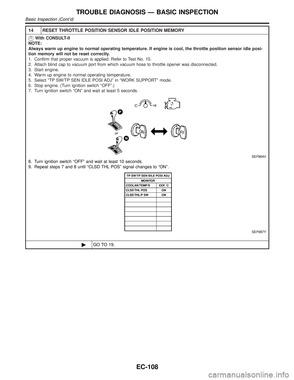
14 RESET THROTTLE POSITION SENSOR IDLE POSITION MEMORY
With CONSULT-II
NOTE:
Always warm up engine to normal operating temperature. If engine is cool, the throttle position sensor idle posi-
tion memory will not be reset correctly.
1. Confirm that proper vacuum is applied. Refer to Test No. 10.
2. Attach blind cap to vacuum port from which vacuum hose to throttle opener was disconnected.
3. Start engine.
4. Warm up engine to normal operating temperature.
5. Select ªTP SW/TP SEN IDLE POSI ADJº in ªWORK SUPPORTº mode.
6. Stop engine. (Turn ignition switch ªOFFº.)
7. Turn ignition switch ªONº and wait at least 5 seconds.
SEF864V
8. Turn ignition switch ªOFFº and wait at least 10 seconds.
9. Repeat steps 7 and 8 until ªCLSD THL POSº signal changes to ªONº.
SEF987Y
©GO TO 19.
TROUBLE DIAGNOSIS Ð BASIC INSPECTION
Basic Inspection (Cont'd)
EC-108
Page 646 of 2395

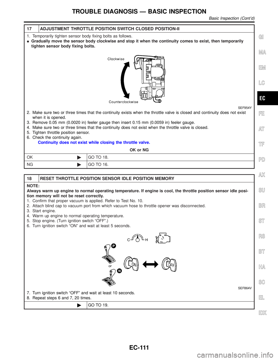
17 ADJUSTMENT THROTTLE POSITION SWITCH CLOSED POSITION-II
1. Temporarily tighten sensor body fixing bolts as follows.
IGradually move the sensor body clockwise and stop it when the continuity comes to exist, then temporarily
tighten sensor body fixing bolts.
SEF954Y
2. Make sure two or three times that the continuity exists when the throttle valve is closed and continuity does not exist
when it is opened.
3. Remove 0.05 mm (0.0020 in) feeler gauge then insert 0.15 mm (0.0059 in) feeler gauge.
4. Make sure two or three times that the continuity does not exist when the throttle valve is closed.
5. Tighten throttle position sensor.
6. Check the continuity again.
Continuity does not exist while closing the throttle valve.
OK or NG
OK©GO TO 18.
NG©GO TO 16.
18 RESET THROTTLE POSITION SENSOR IDLE POSITION MEMORY
NOTE:
Always warm up engine to normal operating temperature. If engine is cool, the throttle position sensor idle posi-
tion memory will not be reset correctly.
1. Confirm that proper vacuum is applied. Refer to Test No. 10.
2. Attach blind cap to vacuum port from which vacuum hose to throttle opener was disconnected.
3. Start engine.
4. Warm up engine to normal operating temperature.
5. Stop engine. (Turn ignition switch ªOFFº.)
6. Turn ignition switch ªONº and wait at least 5 seconds.
SEF864V
7. Turn ignition switch ªOFFº and wait at least 10 seconds.
8. Repeat steps 6 and 7, 20 times.
©GO TO 19.
GI
MA
EM
LC
FE
AT
TF
PD
AX
SU
BR
ST
RS
BT
HA
SC
EL
IDX
TROUBLE DIAGNOSIS Ð BASIC INSPECTION
Basic Inspection (Cont'd)
EC-111
Page 647 of 2395

19 CHECK (1ST TRIP) DTC
1. Turn ignition switch ªOFFº.
2. Release vacuum from throttle opener.
3. Remove vacuum pump and vacuum hose from throttle opener.
4. Reinstall original vacuum hose to throttle opener securely.
5. Start engine and warm it up to normal operating temperature.
6. Rev (2,000 to 3,000 rpm) two or three times.
7. Make sure no (1st trip) DTC is displayed with CONSULT-II or GST.
OK or NG
OK©GO TO 21.
NG©GO TO 20.
20 REPAIR MALFUNCTION
Repair or replace components as necessary according to corresponding ªDiagnostic Procedureº.
©GO TO 19.
21 CHECK TARGET IDLE SPEED
With CONSULT-II
1. Start engine and warm it up to normal operating temperature.
2. Select ªENG SPEEDº in ªDATA MONITORº mode with CONSULT-II.
3. Check idle speed.
750±50 rpm (in ªPº or ªNº position)
Without CONSULT-II
1. Start engine and warm it up to normal operating temperature.
2. Check idle speed.
750±50 rpm (in ªPº or ªNº position)
OK or NG
OK©GO TO 30.
NG©GO TO 22.
22 PERFORM IDLE AIR VOLUME LEARNING
Refer to ªIdle Air Volume Learningº, EC-57.
Which is the result CMPLT or INCMP?
CMPLT or INCMP
CMPLT©GO TO 23.
INCMP©1. Follow the construction of ªIdle Air Volume Leaningº.
2. GO TO 22.
TROUBLE DIAGNOSIS Ð BASIC INSPECTION
Basic Inspection (Cont'd)
EC-112
Page 648 of 2395

23 CHECK TARGET IDLE SPEED AGAIN
With CONSULT-II
1. Start engine and warm it up to normal operating temperature.
2. Select ªENG SPEEDº in ªDATA MONITORº mode with CONSULT-II.
3. Check idle speed.
750±50 rpm (in ªPº or ªNº position)
Without CONSULT-II
1. Start engine and warm it up to normal operating temperature.
2. Check idle speed.
750±50 rpm (in ªPº or ªNº position)
OK or NG
OK©GO TO 28.
NG©GO TO 24.
24 REPLACE IACV-AAC VALVE
Replace IACV-AAC valve.
©GO TO 25.
25 PERFORM IDLE AIR VOLUME LEARNING
Refer to ªIdle Air Volume Learningº, EC-57.
Which is the result CMPLT or INCMP?
CMPLT or INCMP
CMPLT©GO TO 26.
INCMP©1. Follow the construction of ªIdle Air Volume Learningº.
2. GO TO 22.
26 CHECK TARGET IDLE SPEED AGAIN
With CONSULT-II
1. Start engine and warm it up to normal operating temperature.
2. Select ªENG SPEEDº in ªDATA MONITORº mode with CONSULT-II.
3. Check idle speed.
750±50 rpm (in ªPº or ªNº position)
Without CONSULT-II
1. Start engine and warm it up to normal operating temperature.
2. Check idle speed.
750±50 rpm (in ªPº or ªNº position)
OK or NG
OK©GO TO 28.
NG©GO TO 27.
27 CHECK ECM FUNCTION
1. Substitute another known-good ECM to check ECM function. (ECM may be the cause of a problem, but this is rarely
the case.)
2. Perform initialization of IVIS (NATS) system and registration of IVIS (NATS) ignition key IDs. Refer to ªIVIS (INFINITI
VEHICLE IMMOBILIZER SYSTEM Ð NATS)º, EC-74.
©GO TO 22.
GI
MA
EM
LC
FE
AT
TF
PD
AX
SU
BR
ST
RS
BT
HA
SC
EL
IDX
TROUBLE DIAGNOSIS Ð BASIC INSPECTION
Basic Inspection (Cont'd)
EC-113
Page 649 of 2395

28 CHECK IGNITION TIMING
1. Start engine and warm it up to normal operating temperature.
2. Check ignition timing at idle using a timing light.
SEF572X
Ignition timing:
15ɱ5É BTDC (in ªPº or ªNº position)
OK or NG
OK©GO TO 36.
NG©GO TO 29.
29 CHECK TIMING CHAIN INSTALLATION
Check timing chain installation. Refer to EM-29, ªInstallationº.
OK or NG
OK©GO TO 27.
NG©1. Repair the timing chain installation.
2. GO TO 22.
30 CHECK IGNITION TIMING
1. Start engine and let it idle.
2. Check ignition timing at idle using a timing light.
SEF572X
Ignition timing:
15ɱ5É BTDC (in ªPº or ªNº position)
OK or NG
OK©GO TO 36.
NG©GO TO 31.
TROUBLE DIAGNOSIS Ð BASIC INSPECTION
Basic Inspection (Cont'd)
EC-114
Page 650 of 2395

31 PERFORM IDLE AIR VOLUME LEARNING
Refer to ªIdle Air Volume Learningº, EC-57.
Which is the result CMPLT or INCMP?
CMPLT or INCMP
CMPLT©GO TO 32.
INCMP©1. Follow the construction of ªIdle Air volume Learningº.
2. GO TO 31.
32 CHECK TARGET IDLE SPEED AGAIN
With CONSULT-II
1. Start engine and warm it up to normal operating temperature.
2. Select ªENG SPEEDº in ªDATA MONITORº mode with CONSULT-II.
3. Check idle speed.
750±50 rpm (in ªPº or ªNº position)
Without CONSULT-II
1. Start engine and warm it up to normal operating temperature.
2. Check idle speed.
750±50 rpm (in ªPº or ªNº position)
OK or NG
OK©GO TO 34.
NG©GO TO 33.
33 CHECK ECM FUNCTION
1. Substitute another known-good ECM to check ECM function.
(ECM may be the cause of a problem, but this is rarely the case.)
2. Perform initialization of NVIS (NATS) system and registration of NVIS (NATS) ignition key IDs. Refer to ªNVIS (NISSAN
VEHICLE IMMOBILIZER SYSTEM Ð NATS)º, EC-74.
©GO TO 31.
34 CHECK IGNITION TIMING AGAIN
Check ignition timing again. Refer to Test No. 30.
OK or NG
OK©GO TO 36.
NG©GO TO 35.
35 CHECK TIMING CHAIN INSTALLATION
Check timing chain installation. Refer to EM-29, ªInstallationº.
OK or NG
OK©GO TO 33.
NG©1. Repair the timing chain installation.
2. GO TO 31.
36 ERASE UNNECESSARY DTC
After this inspection, unnecessary DTC No. might be displayed.
Erase the stored memory in ECM and TCM (Transmission control module).
Refer to ªHow to Erase Emission-Related Diagnostic Informationº, EC-72 and AT-35, ªHOW TO ERASE DTCº.
©INSPECTION END
GI
MA
EM
LC
FE
AT
TF
PD
AX
SU
BR
ST
RS
BT
HA
SC
EL
IDX
TROUBLE DIAGNOSIS Ð BASIC INSPECTION
Basic Inspection (Cont'd)
EC-115