service INFINITI QX4 2001 Factory Service Manual
[x] Cancel search | Manufacturer: INFINITI, Model Year: 2001, Model line: QX4, Model: INFINITI QX4 2001Pages: 2395, PDF Size: 43.2 MB
Page 2061 of 2395

SPD682
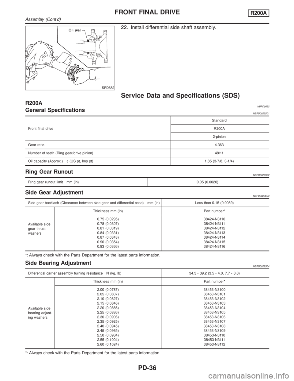
22. Install differential side shaft assembly.
Service Data and Specifications (SDS)
R200ANBPD0022General SpecificationsNBPD0022S01
Front final driveStandard
R200A
2-pinion
Gear ratio4.363
Number of teeth (Ring gear/drive pinion)48/11
Oil capacity (Approx.)(US pt, lmp pt) 1.85 (3-7/8, 3-1/4)
Ring Gear RunoutNBPD0022S02
Ring gear runout limit mm (in)0.05 (0.0020)
Side Gear AdjustmentNBPD0022S03
Side gear backlash (Clearance between side gear and differential case) mm (in) Less than 0.15 (0.0059)
Available side
gear thrust
washersThickness mm (in) Part number*
0.75 (0.0295)
0.78 (0.0307)
0.81 (0.0319)
0.84 (0.0331)
0.87 (0.0343)
0.90 (0.0354)
0.93 (0.0366)38424-N3110
38424-N3111
38424-N3112
38424-N3113
38424-N3114
38424-N3115
38424-N3116
*: Always check with the Parts Department for the latest parts information.
Side Bearing AdjustmentNBPD0022S04
Differential carrier assembly turning resistance N (kg, lb) 34.3 - 39.2 (3.5 - 4.0, 7.7 - 8.8)
Available side
bearing adjust-
ing washersThickness mm (in) Part number*
2.00 (0.0787)
2.05 (0.0807)
2.10 (0.0827)
2.15 (0.0846)
2.20 (0.0866)
2.25 (0.0886)
2.30 (0.0906)
2.35 (0.0925)
2.40 (0.0945)
2.45 (0.0965)
2.50 (0.0984)
2.55 (0.1004)
2.60 (0.1024)38453-N3100
38453-N3101
38453-N3102
38453-N3103
38453-N3104
38453-N3105
38453-N3106
38453-N3107
38453-N3108
38453-N3109
38453-N3110
38453-N3111
38453-N3112
*: Always check with the Parts Department for the latest parts information.
FRONT FINAL DRIVER200A
Assembly (Cont'd)
PD-36
Page 2062 of 2395
![INFINITI QX4 2001 Factory Service Manual Total Preload AdjustmentNBPD0022S05
Total preload N´m (kg-cm, in-lb) P1+ [0.3 - 1.5 (3 - 15, 2.6 - 13.0)]
Ring gear backlash mm (in) 0.10 - 0.15 (0.0039 - 0.0059)
P1: Drive pinion preload
Drive Pinio INFINITI QX4 2001 Factory Service Manual Total Preload AdjustmentNBPD0022S05
Total preload N´m (kg-cm, in-lb) P1+ [0.3 - 1.5 (3 - 15, 2.6 - 13.0)]
Ring gear backlash mm (in) 0.10 - 0.15 (0.0039 - 0.0059)
P1: Drive pinion preload
Drive Pinio](/img/42/57027/w960_57027-2061.png)
Total Preload AdjustmentNBPD0022S05
Total preload N´m (kg-cm, in-lb) P1+ [0.3 - 1.5 (3 - 15, 2.6 - 13.0)]
Ring gear backlash mm (in) 0.10 - 0.15 (0.0039 - 0.0059)
P1: Drive pinion preload
Drive Pinion Height AdjustmentNBPD0022S06
Available pin-
ion height
adjusting
washersThickness mm (in) Part number*
3.09 (0.1217)
3.12 (0.1228)
3.15 (0.1240)
3.18 (0.1252)
3.21 (0.1264)
3.24 (0.1276)
3.27 (0.1287)
3.30 (0.1299)
3.33 (0.1311)
3.36 (0.1323)
3.39 (0.1335)
3.42 (0.1346)
3.45 (0.1358)
3.48 (0.1370)
3.51 (0.1382)
3.54 (0.1394)
3.57 (0.1406)
3.60 (0.1417)
3.63 (0.1429)
3.66 (0.1441)38154-P6017
38154-P6018
38154-P6019
38154-P6020
38154-P6021
38154-P6022
38154-P6023
38154-P6024
38154-P6025
38154-P6026
38154-P6027
38154-P6028
38154-P6029
38154-P6030
38154-P6031
38154-P6032
38154-P6033
38154-P6034
38154-P6035
38154-P6036
*: Always check with the Parts Department for the latest parts information.
Drive Pinion Preload AdjustmentNBPD0022S07
Drive pinion bearing preload adjusting method Adjusting washer and spacer
Drive pinion preload with front oil seal N´m (kg-cm, in-lb) [P
1] 1.1 - 1.4 (11 - 14, 9.5 - 12.2)
Available drive
pinion bearing
preload adjust-
ing washersThickness mm (in) Part number*
3.81 (0.1500)
3.83 (0.1508)
3.85 (0.1516)
3.87 (0.1524)
3.89 (0.1531)
3.91 (0.1539)
3.93 (0.1547)
3.95 (0.1555)
3.97 (0.1563)
3.99 (0.1571)
4.01 (0.1579)
4.03 (0.1587)
4.05 (0.1594)
4.07 (0.1602)
4.09 (0.1610)38125-61001
38126-61001
38127-61001
38128-61001
38129-61001
38130-61001
38131-61001
38132-61001
38133-61001
38134-61001
38135-61001
38136-61001
38137-61001
38138-61001
38139-61001
Available drive
pinion bearing
preload adjust-
ing spacersLength mm (in) Part number*
54.50 (2.1457)
54.80 (2.1575)
55.10 (2.1693)
55.40 (2.1811)
55.70 (2.1929)
56.00 (2.2047)38165-B4000
38165-B4001
38165-B4002
38165-B4003
38165-B4004
38165-61001
*: Always check with the Parts Department for the latest parts information.
GI
MA
EM
LC
EC
FE
AT
TF
AX
SU
BR
ST
RS
BT
HA
SC
EL
IDX
FRONT FINAL DRIVER200A
Service Data and Specifications (SDS) (Cont'd)
PD-37
Page 2063 of 2395

Preparation
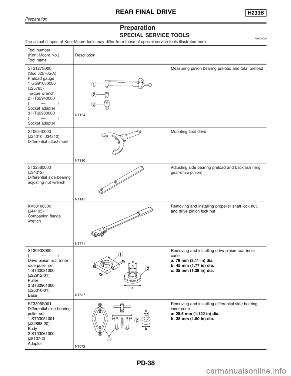
SPECIAL SERVICE TOOLSNBPD0029The actual shapes of Kent-Moore tools may differ from those of special service tools illustrated here.
Tool number
(Kent-Moore No.)
Tool nameDescription
ST3127S000
(See J25765-A)
Preload gauge
1 GG91030000
(J25765)
Torque wrench
2 HT62940000
(Ð)
Socket adapter
3 HT62900000
(Ð)
Socket adapter
NT124
Measuring pinion bearing preload and total preload
ST06340000
(J24310, J34310)
Differential attachment
NT140
Mounting final drive
ST32580000
(J34312)
Differential side bearing
adjusting nut wrench
NT141
Adjusting side bearing preload and backlash (ring
gear-drive pinion)
KV38108300
(J44195)
Companion flange
wrench
NT771
Removing and installing propeller shaft lock nut,
and drive pinion lock nut
ST3090S000
(Ð)
Drive pinion rear inner
race puller set
1 ST30031000
(J22912-01)
Puller
2 ST30901000
(J26010-01)
Base
NT527
Removing and installing drive pinion rear inner
cone
a: 79 mm (3.11 in) dia.
b: 45 mm (1.77 in) dia.
c: 35 mm (1.38 in) dia.
ST3306S001
Differential side bearing
puller set
1 ST33051001
(J22888-20)
Body
2 ST33061000
(J8107-2)
Adapter
NT072
Removing and installing differential side bearing
inner cone
a: 28.5 mm (1.122 in) dia.
b: 38 mm (1.50 in) dia.
REAR FINAL DRIVEH233B
Preparation
PD-38
Page 2065 of 2395

Tool number
(Kent-Moore No.)
Tool nameDescription
(J25269-18)
Side bearing discs
(2 Req'd)
NT135
Selecting pinion height adjusting washer
KV381052S0
(Ð)
Rear axle shaft dummy
1 KV38105210
(Ð)
Torque wrench side
2 KV38105220
(Ð)
Vice side
NT142
Checking differential torque on limited slip differen-
tial
KV38100500
(J25273)
Gear carrier front oil
seal drift
NT115
Installing front oil seal
a: 85 mm (3.35 in) dia.
b: 60 mm (2.36 in) dia.
Noise, Vibration and Harshness (NVH)
Troubleshooting
NBPD0051Refer to ªNVH TROUBLESHOOTING CHARTº, PD-3.
SPD479A
On-vehicle Service
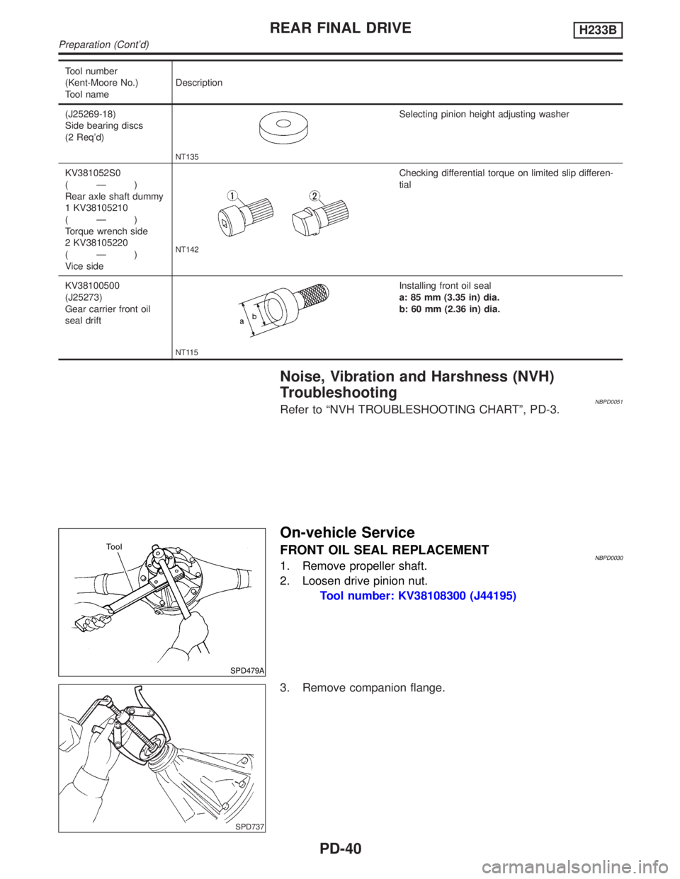
FRONT OIL SEAL REPLACEMENTNBPD00301. Remove propeller shaft.
2. Loosen drive pinion nut.
Tool number: KV38108300 (J44195)
SPD737
3. Remove companion flange.
REAR FINAL DRIVEH233B
Preparation (Cont'd)
PD-40
Page 2066 of 2395

SPD738
4. Remove front oil seal.
SPD739
5. Apply multi-purpose grease to cavity at sealing lips of oil seal.
Press front oil seal into carrier.
Tool number:
KV38100500 (J25273)
6. Install companion flange and drive pinion nut.
7. Install rear propeller shaft.
GI
MA
EM
LC
EC
FE
AT
TF
AX
SU
BR
ST
RS
BT
HA
SC
EL
IDX
REAR FINAL DRIVEH233B
On-vehicle Service (Cont'd)
PD-41
Page 2087 of 2395

Service Data and Specifications (SDS)
H233B=NBPD0042General SpecificationsNBPD0042S01
Rear final drive2WD 4WD
Standard Optional
H233B
2-pinion LSD
Gear ratio4.363
Number of teeth (Ring gear/drive pinion) 48/11
Oil capacity (Approx.)(US pt, lmp pt) 2.8 (5-7/8, 4-7/8)
Ring Gear RunoutNBPD0042S02
Ring gear runout limit mm (in)0.08 (0.0031)
Side Gear AdjustmentNBPD0042S03
Side gear backlash (Clearance between side gear and differential case) mm (in) 0.10 - 0.20 (0.0039 - 0.0079)
Available side
gear thrust
washersThickness mm (in) Part number*
1.75 (0.0689)
1.80 (0.0709)
1.85 (0.0728)38424-T5000
38424-T5001
38424-T5002
*: Always check with the Parts Department for the latest parts information.
Differential Torque Adjustment (LSD models)NBPD0042S04
Differential torque N´m (kg-m, ft-lb) 88 - 108 (9 - 11, 65 - 80)
Number of discs and plates (One
side)Friction disc 2
Friction plate 9
Spring plate 2
Wear limit of plate and disc mm (in) 0.1 (0.004)
Allowable warpage of friction disc and plate mm (in) 0.08 (0.0031)
Available discs
and platesPlate name Thickness mm (in) Part number*
Friction disc1.48 - 1.52 (0.0583 - 0.0598)
1.38 - 1.42 (0.0543 - 0.0559)
1.58 - 1.62 (0.0622 - 0.0638)38433-C6002 (Standard type)
38433-C6004 (Adjusting type)
38433-C6003 (Adjusting type)
Friction plate1.48 - 1.52 (0.0583 - 0.0598)
1.38 - 1.42 (0.0543 - 0.0559)
1.58 - 1.62 (0.0622 - 0.0638)38432-C6001
38432-C6002
38432-C6003
Spring plate 1.48 - 1.52 (0.0583 - 0.0598) 38435-S9200
*: Always check with the Parts Department for the latest parts information.
Total Preload AdjustmentNBPD0042S05
Total preload N´m (kg-cm, in-lb) P1+ [0.3 - 0.4 (3 - 4, 2.6 - 3.5)]
Ring gear backlash mm (in) 0.13 - 0.18 (0.0051 - 0.0071)
Side bearing adjusting methodSide adjuster
P1: Drive pinion preload
REAR FINAL DRIVEH233B
Service Data and Specifications (SDS)
PD-62
Page 2088 of 2395

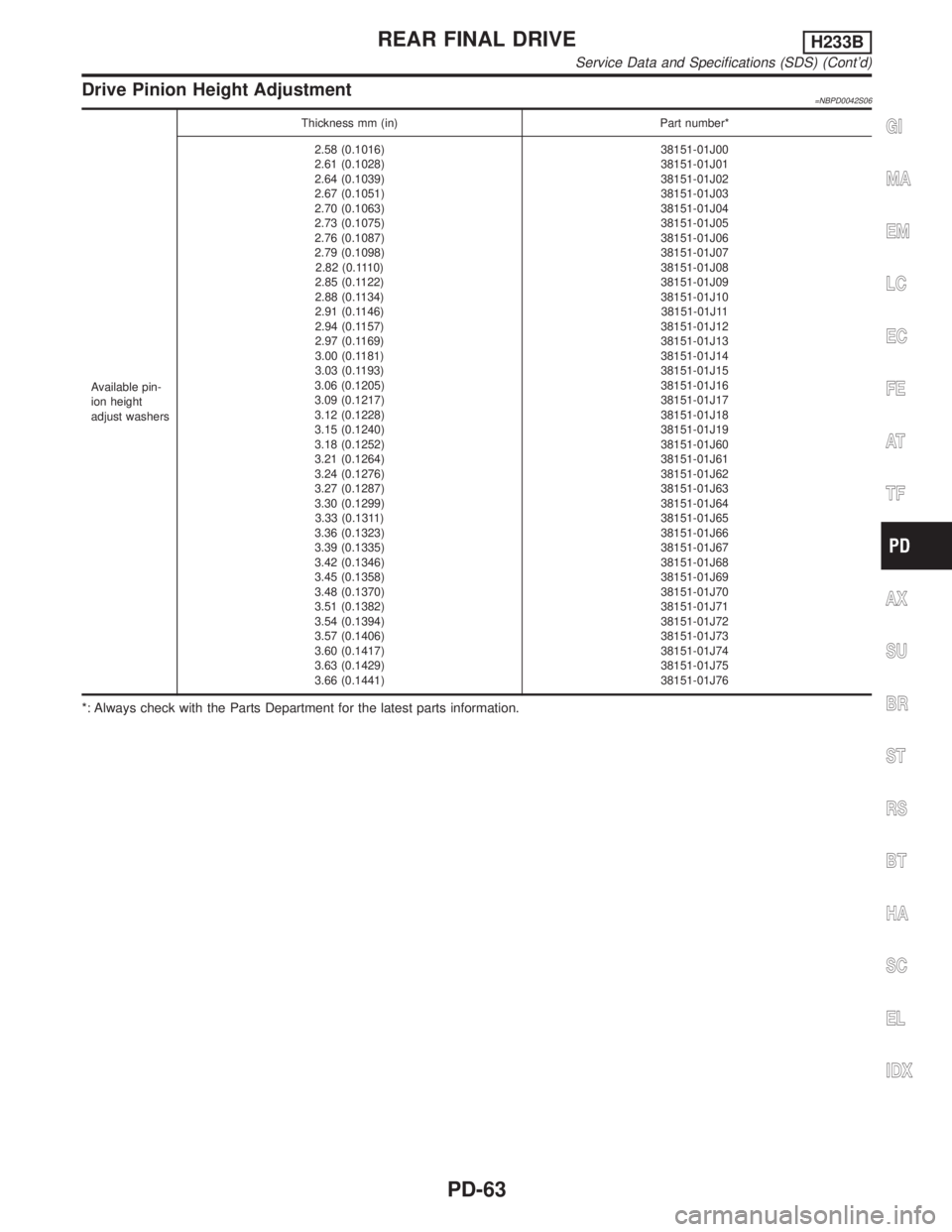
Drive Pinion Height Adjustment=NBPD0042S06
Available pin-
ion height
adjust washersThickness mm (in) Part number*
2.58 (0.1016)
2.61 (0.1028)
2.64 (0.1039)
2.67 (0.1051)
2.70 (0.1063)
2.73 (0.1075)
2.76 (0.1087)
2.79 (0.1098)
2.82 (0.1110)
2.85 (0.1122)
2.88 (0.1134)
2.91 (0.1146)
2.94 (0.1157)
2.97 (0.1169)
3.00 (0.1181)
3.03 (0.1193)
3.06 (0.1205)
3.09 (0.1217)
3.12 (0.1228)
3.15 (0.1240)
3.18 (0.1252)
3.21 (0.1264)
3.24 (0.1276)
3.27 (0.1287)
3.30 (0.1299)
3.33 (0.1311)
3.36 (0.1323)
3.39 (0.1335)
3.42 (0.1346)
3.45 (0.1358)
3.48 (0.1370)
3.51 (0.1382)
3.54 (0.1394)
3.57 (0.1406)
3.60 (0.1417)
3.63 (0.1429)
3.66 (0.1441)38151-01J00
38151-01J01
38151-01J02
38151-01J03
38151-01J04
38151-01J05
38151-01J06
38151-01J07
38151-01J08
38151-01J09
38151-01J10
38151-01J11
38151-01J12
38151-01J13
38151-01J14
38151-01J15
38151-01J16
38151-01J17
38151-01J18
38151-01J19
38151-01J60
38151-01J61
38151-01J62
38151-01J63
38151-01J64
38151-01J65
38151-01J66
38151-01J67
38151-01J68
38151-01J69
38151-01J70
38151-01J71
38151-01J72
38151-01J73
38151-01J74
38151-01J75
38151-01J76
*: Always check with the Parts Department for the latest parts information.
GI
MA
EM
LC
EC
FE
AT
TF
AX
SU
BR
ST
RS
BT
HA
SC
EL
IDX
REAR FINAL DRIVEH233B
Service Data and Specifications (SDS) (Cont'd)
PD-63
Page 2089 of 2395
![INFINITI QX4 2001 Factory Service Manual Drive Pinion Preload Adjustment=NBPD0042S07
Drive pinion bearing preload adjusting method Adjusting shim and spacer
Drive pinion preload without front oil seal N´m (kg-cm, in-lb) [P
1] 1.2 - 2.0 (12 INFINITI QX4 2001 Factory Service Manual Drive Pinion Preload Adjustment=NBPD0042S07
Drive pinion bearing preload adjusting method Adjusting shim and spacer
Drive pinion preload without front oil seal N´m (kg-cm, in-lb) [P
1] 1.2 - 2.0 (12](/img/42/57027/w960_57027-2088.png)
Drive Pinion Preload Adjustment=NBPD0042S07
Drive pinion bearing preload adjusting method Adjusting shim and spacer
Drive pinion preload without front oil seal N´m (kg-cm, in-lb) [P
1] 1.2 - 2.0 (12 - 20, 10 - 17)
Available front
drive pinion
bearing adjust-
ing shimsThickness mm (in) Part number*
2.31 (0.0909)
2.33 (0.0917)
2.35 (0.0925)
2.37 (0.0933)
2.39 (0.0941)
2.41 (0.0949)
2.43 (0.0957)
2.45 (0.0965)
2.47 (0.0972)
2.49 (0.0980)
2.51 (0.0988)
2.53 (0.0996)
2.55 (0.1004)
2.57 (0.1012)
2.59 (0.1020)38125-82100
38126-82100
38127-82100
38128-82100
38129-82100
38130-82100
38131-82100
38132-82100
38133-82100
38134-82100
38135-82100
38136-82100
38137-82100
38138-82100
38139-82100
Available drive
pinion bearing
adjusting spac-
ersThickness mm (in) Part number*
4.50 (0.1772)
4.75 (0.1870)
5.00 (0.1969)
5.25 (0.2067)
5.50 (0.2165)38165-76000
38166-76000
38167-76000
38166-01J00
38166-01J10
*: Always check with the Parts Department for the latest parts information.
REAR FINAL DRIVEH233B
Service Data and Specifications (SDS) (Cont'd)
PD-64
Page 2090 of 2395

RESTRAINT SYSTEM
SECTION
RS
CONTENTS
SEAT BELTS...................................................................3
Precautions ..................................................................3
SUPPLEMENTAL RESTRAINT SYSTEM (SRS)
²AIR BAG²AND²SEAT BELT PRE-TENSIONER²
........3
PRECAUTION FOR SEAT BELT SERVICE..................3
Front Seat Belt.............................................................4
REMOVAL AND INSTALLATION.................................4
Rear Seat Belt .............................................................5
REMOVAL AND INSTALLATION.................................5
Seat Belt Inspection.....................................................7
AFTER A COLLISION.................................................7
PRELIMINARY CHECKS............................................7
SEAT BELT RETRACTOR ON-VEHICLE CHECK.........8
SEAT BELT RETRACTOR OFF-VEHICLE CHECK.......8
SUPPLEMENTAL RESTRAINT SYSTEM (SRS).........10
Precautions ................................................................10
SUPPLEMENTAL RESTRAINT SYSTEM (SRS)
²AIR BAG²AND²SEAT BELT PRE-TENSIONER²
......10
PRECAUTIONS FOR SRS²AIR BAG²AND²SEAT
BELT PRE-TENSIONER²SERVICE
...........................10
WIRING DIAGRAMS AND TROUBLE DIAGNOSIS.....10
Preparation ................................................................ 11
SPECIAL SERVICE TOOLS...................................... 11
Description .................................................................12
Seat Belt Pre-tensioner with Load Limiter.................12
Built-in Type Side Air Bag..........................................13
SRS Component Parts Location ...............................13
Maintenance Items ....................................................14
Diagnosis Sensor Unit ...............................................15
REMOVAL AND INSTALLATION...............................15
Seat Belt Pre-tensioner .............................................15
REMOVAL AND INSTALLATION...............................15
Satellite Sensor..........................................................16
REMOVAL AND INSTALLATION...............................16
Driver Air Bag Module and Spiral Cable ...................17
REMOVAL AND INSTALLATION...............................17
REMOVAL...............................................................17
INSTALLATION........................................................18
Front Passenger Air Bag Module ..............................19
REMOVAL...............................................................19
INSTALLATION........................................................20
Side Air Bag Module ..................................................21
REMOVAL...............................................................21
INSTALLATION........................................................22
Disposal of Air Bag Module and Seat Belt Pre-
tensioner ....................................................................22
CHECKING DEPLOYMENT TOOL.............................23
DEPLOYMENT PROCEDURES FOR AIR BAG
MODULE (OUTSIDE OF VEHICLE)
...........................24
DEPLOYMENT PROCEDURES FOR SEAT BELT
PRE-TENSIONER (OUTSIDE OF VEHICLE)
..............27
DEPLOYMENT OF AIR BAG MODULE AND SEAT
BELT PRE-TENSIONER WHILE MOUNTED IN
VEHICLE
.................................................................27
DISPOSING OF AIR BAG MODULE AND SEAT
BELT PRE-TENSIONER
...........................................28
Trouble Diagnoses Introduction.................................29
DIAGNOSIS FUNCTION...........................................29
DIAGNOSIS MODE FOR CONSULT-II.......................29
HOW TO CHANGE SELF-DIAGNOSIS MODE
WITH CONSULT-II
...................................................30
HOW TO CHANGE SELF-DIAGNOSIS MODE
WITHOUT CONSULT-II
............................................30
HOW TO ERASE SELF-DIAGNOSIS RESULTS.........30
How to Perform Trouble Diagnoses for Quick
and Accurate Repair ..................................................32
INFORMATION FROM CUSTOMER..........................32
PRELIMINARY CHECK............................................32
WORK FLOW..........................................................33
Schematic ..................................................................34
Wiring Diagram - SRS -.............................................35
SRS Operation Check ...............................................38
DIAGNOSTIC PROCEDURE 1..................................38
Trouble Diagnoses with CONSULT-II...................39
DIAGNOSTIC PROCEDURE 2..................................39
DIAGNOSTIC PROCEDURE 3..................................42
DIAGNOSTIC PROCEDURE 4 (CONTINUED
FROM DIAGNOSTIC PROCEDURE 2)
......................44
DIAGNOSTIC PROCEDURE 5..................................44
Trouble Diagnoses without CONSULT-II..............48
DIAGNOSTIC PROCEDURE 6..................................48
GI
MA
EM
LC
EC
FE
AT
TF
PD
AX
SU
BR
ST
BT
HA
SC
EL
IDX
Page 2092 of 2395

Precautions
SUPPLEMENTAL RESTRAINT SYSTEM (SRS) ªAIR BAGº AND ªSEAT BELT
PRE-TENSIONERº
NBRS0001The Supplemental Restraint System such as ªAIR BAGº and ªSEAT BELT PRE-TENSIONERº used along with
a seat belt, helps to reduce the risk or severity of injury to the driver and front passenger for certain types of
collision. The SRS composition which is available to INFINITI QX4 is as follows:
IFor a frontal collision
The Supplemental Restraint System consists of driver air bag module (located in the center of the steer-
ing wheel), front passenger air bag module (located on the instrument panel on passenger side), seat belt
pre-tensioners, a diagnosis sensor unit, warning lamp, wiring harness and spiral cable.
IFor a side collision
The Supplemental Restraint System consists of side air bag module (located in the outer side of front seat),
satellite sensor, diagnosis sensor unit (one of components of air bags for a frontal collision), wiring harness,
warning lamp (one of components of air bags for a frontal collision).
WARNING:
ITo avoid rendering the SRS inoperative, which could increase the risk of personal injury or death
in the event of a collision which would result in air bag inflation, all maintenance must be performed
by an authorized INFINITI dealer.
IImproper maintenance, including incorrect removal and installation of the SRS, can lead to per-
sonal injury caused by unintentional activation of the system.
IDo not use electrical test equipment on any circuit related to the SRS unless instructed to in this
Service Manual. Spiral cable and wiring harnesses covered with yellow insulation tape either just
before the harness connectors or for the complete harness are related to the SRS.
PRECAUTION FOR SEAT BELT SERVICENBRS0002CAUTION:
IBefore removing the seat belt pre-tensioner assembly, turn the ignition switch off, disconnect both
battery cables and wait at least 3 minutes.
IDo not use electrical test equipment for seat belt pre-tensioner connector.
IAfter replacing or reinstalling seat belt pre-tensioner assembly, or reconnecting seat belt pre-ten-
sioner connector, check the system function. Refer to ªSRS Operation Checkº (RS-38) for details.
IDo not use disassemble buckle or seat belt assembly.
IReplace anchor bolts if they are deformed or worn out.
INever oil tongue and buckle.
IIf any component of seat belt assembly is questionable, do not repair. Replace the whole seat belt
assembly.
IIf webbing is cut, frayed, or damaged, replace seat belt assembly.
IWhen replacing seat belt assembly, use a genuine seat belt assembly.
After A CollisionNBRS0002S01WARNING:
Inspect all seat belt assemblies including retractors and attaching hardware after any collision.
NISSAN recommends that all seat belt assemblies in use during a collision be replaced unless the
collision was minor and the belts show no damage and continue to operate properly. Failure to do so
could result in serious personal injury in an accident. Seat belt assemblies not in use during a colli-
sion should also be replaced if either damage or improper operation is noted. Seat belt pre-tensioner
should be replaced even if the seat belts are not in use during a frontal collision in which the air bags
are deployed.
Replace any seat belt assembly if:
IThe seat belt was in use at the time of a collision (except for minor collisions and the belts, retractors and
buckles show no damage and continue to operate properly).
IThe seat belt was damaged in an accident. (i.e. torn webbing, bent retractor or guide, etc.)
IThe seat belt attaching point was damaged in an accident. Inspect the seat belt attaching area for dam-
age or distortion and repair as necessary before installing a new seat belt assembly.
IAnchor bolts are deformed or worn out.
IThe seat belt pre-tensioner should be replaced even if the seat belts are not in use during the collision in
which the air bags are deployed.
GI
MA
EM
LC
EC
FE
AT
TF
PD
AX
SU
BR
ST
BT
HA
SC
EL
IDX
SEAT BELTS
Precautions
RS-3