service INFINITI QX4 2001 Factory Service Manual
[x] Cancel search | Manufacturer: INFINITI, Model Year: 2001, Model line: QX4, Model: INFINITI QX4 2001Pages: 2395, PDF Size: 43.2 MB
Page 1970 of 2395
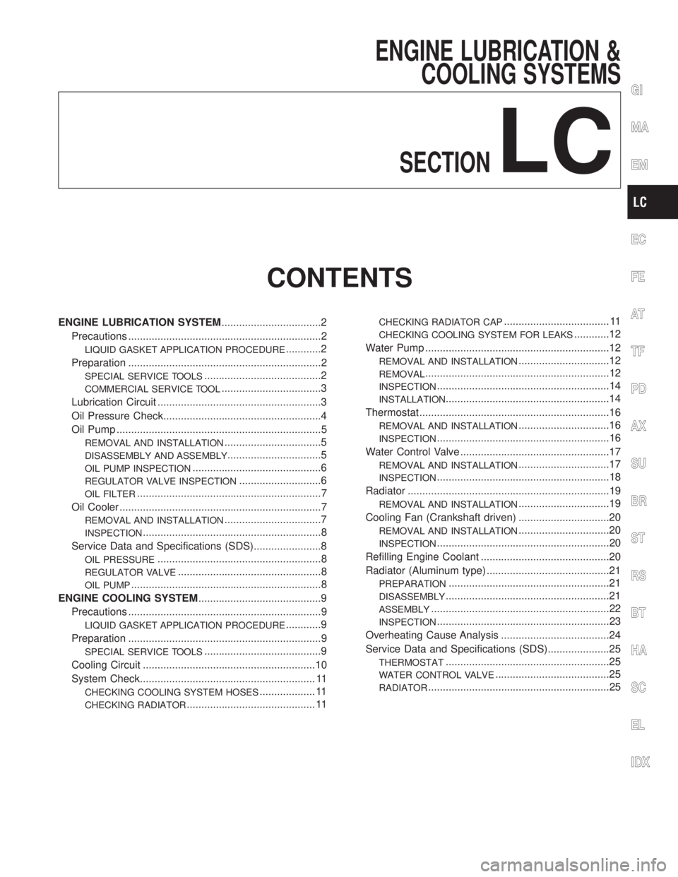
ENGINE LUBRICATION &
COOLING SYSTEMS
SECTION
LC
CONTENTS
ENGINE LUBRICATION SYSTEM..................................2
Precautions ..................................................................2
LIQUID GASKET APPLICATION PROCEDURE............2
Preparation ..................................................................2
SPECIAL SERVICE TOOLS........................................2
COMMERCIAL SERVICE TOOL..................................3
Lubrication Circuit ........................................................3
Oil Pressure Check......................................................4
Oil Pump ......................................................................5
REMOVAL AND INSTALLATION.................................5
DISASSEMBLY AND ASSEMBLY................................5
OIL PUMP INSPECTION............................................6
REGULATOR VALVE INSPECTION............................6
OIL FILTER...............................................................7
Oil Cooler .....................................................................7
REMOVAL AND INSTALLATION.................................7
INSPECTION.............................................................8
Service Data and Specifications (SDS).......................8
OIL PRESSURE........................................................8
REGULATOR VALVE.................................................8
OIL PUMP.................................................................8
ENGINE COOLING SYSTEM..........................................9
Precautions ..................................................................9
LIQUID GASKET APPLICATION PROCEDURE............9
Preparation ..................................................................9
SPECIAL SERVICE TOOLS........................................9
Cooling Circuit ...........................................................10
System Check............................................................ 11
CHECKING COOLING SYSTEM HOSES................... 11
CHECKING RADIATOR............................................ 11
CHECKING RADIATOR CAP.................................... 11
CHECKING COOLING SYSTEM FOR LEAKS............12
Water Pump ...............................................................12
REMOVAL AND INSTALLATION...............................12
REMOVAL...............................................................12
INSPECTION...........................................................14
INSTALLATION........................................................14
Thermostat .................................................................16
REMOVAL AND INSTALLATION...............................16
INSPECTION...........................................................16
Water Control Valve ...................................................17
REMOVAL AND INSTALLATION...............................17
INSPECTION...........................................................18
Radiator .....................................................................19
REMOVAL AND INSTALLATION...............................19
Cooling Fan (Crankshaft driven) ...............................20
REMOVAL AND INSTALLATION...............................20
INSPECTION...........................................................20
Refilling Engine Coolant ............................................20
Radiator (Aluminum type) ..........................................21
PREPARATION.......................................................21
DISASSEMBLY........................................................21
ASSEMBLY.............................................................22
INSPECTION...........................................................23
Overheating Cause Analysis .....................................24
Service Data and Specifications (SDS).....................25
THERMOSTAT........................................................25
WATER CONTROL VALVE.......................................25
RADIATOR..............................................................25
GI
MA
EM
EC
FE
AT
TF
PD
AX
SU
BR
ST
RS
BT
HA
SC
EL
IDX
Page 1971 of 2395

SEM164F
AEM080
Precautions
LIQUID GASKET APPLICATION PROCEDURENBLC00011. Use a scraper to remove all traces of old liquid gasket from
mating surfaces and grooves. Also, completely clean any oil
from these areas.
2. Apply a continuous bead of liquid gasket to mating surfaces.
(Use Genuine RTV silicone sealant Part No. 999MP-A7007
or equivalent.)
IFor oil pan, be sure liquid gasket diameter is 4.0 to 5.0 mm
(0.157 to 0.197 in).
IFor areas except oil pan, be sure liquid gasket diameter is 2.0
to 3.0 mm (0.079 to 0.118 in).
3. Apply liquid gasket around the inner side of bolt holes (unless
otherwise specified).
4. Assembly should be done within 5 minutes after coating.
5. Wait at least 30 minutes before refilling engine oil and engine
coolant.
Preparation
SPECIAL SERVICE TOOLSNBLC0002The actual shapes of Kent-Moore tools may differ from those of special service tools illustrated here.
Tool number
(Kent-Moore No.)
Tool nameDescription
ST25051001
(J25695-1)
Oil pressure gauge
NT050
ST25052000
(J25695-2)
Hose
NT559
Adapting oil pressure gauge to upper oil pan
WS39930000
(Ð)
Tube pressure
NT052
Pressing the tube of liquid gasket
ENGINE LUBRICATION SYSTEM
Precautions
LC-2
Page 1972 of 2395

COMMERCIAL SERVICE TOOLNBLC0040
Tool name Description
Deep socket
NT818
Removing and installing oil pressure switch
Deep socket 26 mm, 3/8 drive
Lubrication CircuitNBLC0003
SLC350BA
GI
MA
EM
EC
FE
AT
TF
PD
AX
SU
BR
ST
RS
BT
HA
SC
EL
IDX
ENGINE LUBRICATION SYSTEM
Preparation (Cont'd)
LC-3
Page 1973 of 2395
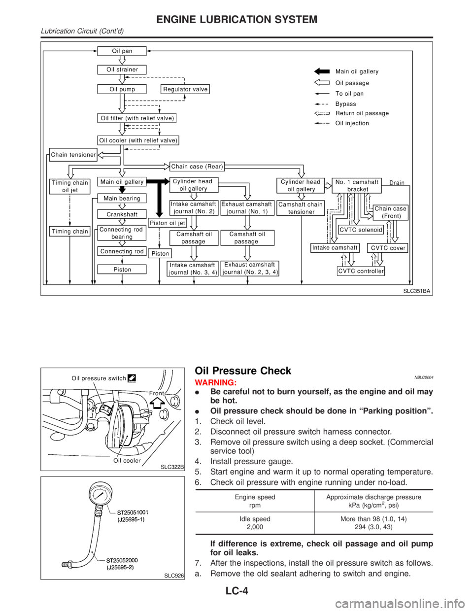
SLC351BA
SLC322B
SLC926
Oil Pressure CheckNBLC0004WARNING:
IBe careful not to burn yourself, as the engine and oil may
be hot.
IOil pressure check should be done in ªParking positionº.
1. Check oil level.
2. Disconnect oil pressure switch harness connector.
3. Remove oil pressure switch using a deep socket. (Commercial
service tool)
4. Install pressure gauge.
5. Start engine and warm it up to normal operating temperature.
6. Check oil pressure with engine running under no-load.
Engine speed
rpmApproximate discharge pressure
kPa (kg/cm2, psi)
Idle speed
2,000More than 98 (1.0, 14)
294 (3.0, 43)
If difference is extreme, check oil passage and oil pump
for oil leaks.
7. After the inspections, install the oil pressure switch as follows.
a. Remove the old sealant adhering to switch and engine.
ENGINE LUBRICATION SYSTEM
Lubrication Circuit (Cont'd)
LC-4
Page 1977 of 2395

IInspect the oil cooler after removing it.
SLC333B
3. Installation is in reverse order of removal.
IWhen installing the oil cooler, align the oil cooler stopper
with the stopper of the oil cooler bracket.
INSPECTIONNBLC0037Oil CoolerNBLC0037S011. Check oil cooler for cracks.
2. Check oil cooler for clogging by blowing through coolant inlet.
If necessary, replace oil cooler assembly.
Oil Pressure Relief ValveNBLC0037S02Inspect oil pressure relief valve for movement, cracks and breaks
by pushing the ball. If replacement is necessary, remove valve by
prying it out with a suitable tool. Install a new valve in place by
tapping it.
Service Data and Specifications (SDS)
OIL PRESSURENBLC0010
Engine speed
rpmApproximate discharge pressure
kPa (kg/cm2, psi)
Idle speed
2,000More than 98 (1.0, 14)
294 (3.0, 43)
REGULATOR VALVENBLC0011Unit: mm (in)
Regulator valve to oil pump cover clearance 0.040 - 0.097 (0.0016 - 0.0038)
OIL PUMPNBLC0012Unit: mm (in)
Body to outer rotor radial clearance 0.114 - 0.200 (0.0045 - 0.0079)
Inner rotor to outer rotor tip clearance Below 0.18 (0.0071)
Body to inner rotor axial clearance 0.030 - 0.070 (0.0012 - 0.0028)
Body to outer rotor axial clearance 0.050 - 0.110 (0.0020 - 0.0043)
Inner rotor to brazed portion of housing clearance 0.045 - 0.091 (0.0018 - 0.0036)
ENGINE LUBRICATION SYSTEM
Oil Cooler (Cont'd)
LC-8
Page 1978 of 2395

SEM164F
AEM080
Precautions
LIQUID GASKET APPLICATION PROCEDURENBLC00131. Use a scraper to remove all traces of old liquid gasket from
mating surfaces and grooves. Also, completely clean any oil
from these areas.
2. Apply a continuous bead of liquid gasket to mating surfaces.
(Use Genuine RTV silicone sealant Part No. 999MP-A7007
or equivalent.)
IFor oil pan, be sure liquid gasket diameter is 4.0 to 5.0 mm
(0.157 to 0.197 in).
IFor areas except oil pan, be sure liquid gasket diameter is 2.0
to 3.0 mm (0.079 to 0.118 in).
3. Apply liquid gasket around the inner side of bolt holes (unless
otherwise specified).
4. Assembly should be done within 5 minutes after coating.
5. Wait at least 30 minutes before refilling engine oil and engine
coolant.
Preparation
SPECIAL SERVICE TOOLSNBLC0014The actual shapes of Kent-Moore tools may differ from those of special service tools illustrated here.
Tool number
(Kent-Moore No.)
Tool nameDescription
WS39930000
(Ð)
Tube pressure
NT052
Pressing the tube of liquid gasket
EG17650301
(J33984-A)
Radiator cap tester
adapter
NT564
Adapting radiator cap tester to radiator filler neck
a: 28 (1.10) dia.
b: 31.4 (1.236) dia.
c: 41.3 (1.626) dia.
Unit: mm (in)
KV99103510
(Ð)
Radiator plate pliers A
NT224
Installing radiator upper and lower tanks
KV99103520
(Ð)
Radiator plate pliers B
NT225
Removing radiator upper and lower tanks
GI
MA
EM
EC
FE
AT
TF
PD
AX
SU
BR
ST
RS
BT
HA
SC
EL
IDX
ENGINE COOLING SYSTEM
Precautions
LC-9
Page 1994 of 2395
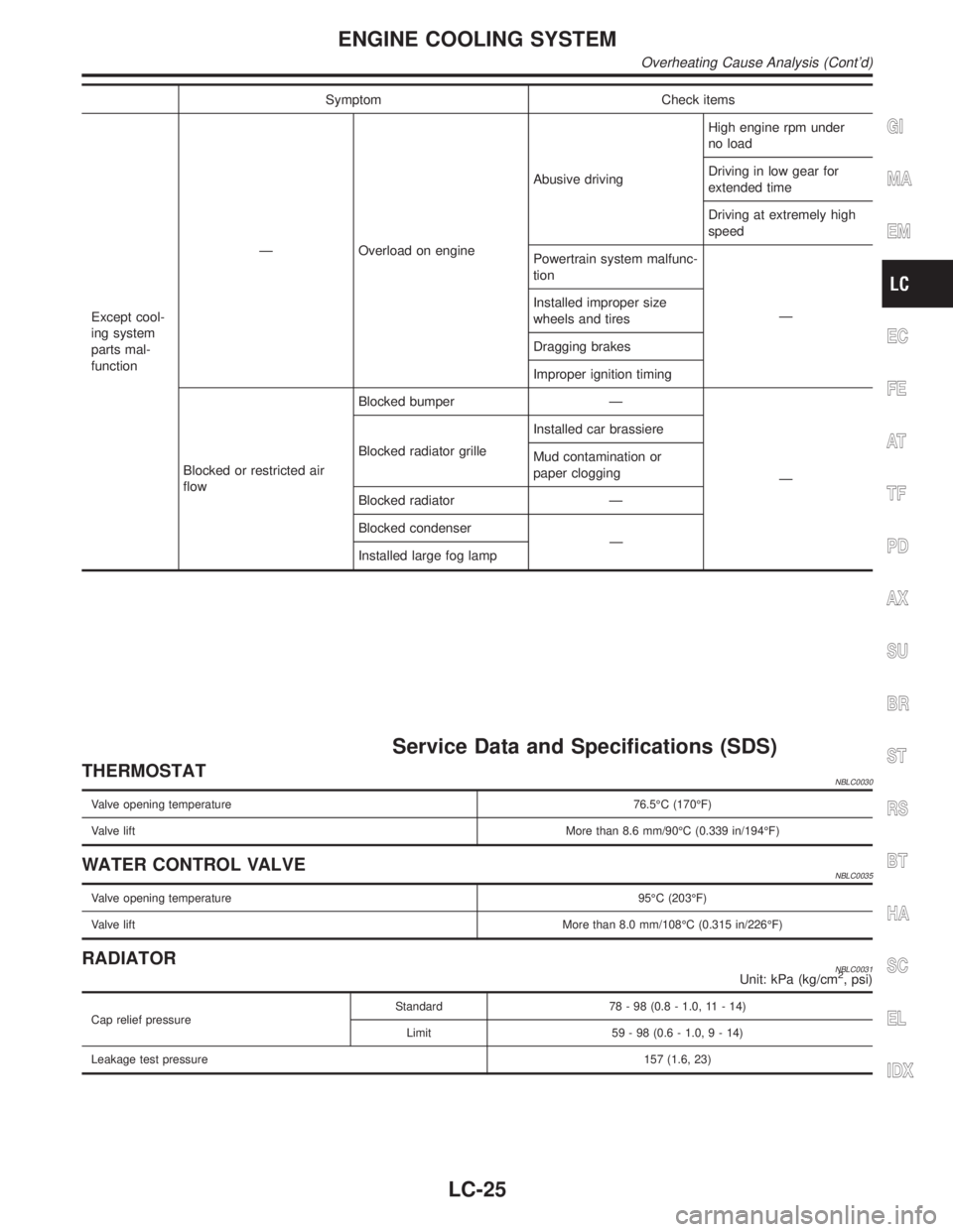
Symptom Check items
Except cool-
ing system
parts mal-
functionÐ Overload on engineAbusive drivingHigh engine rpm under
no load
Driving in low gear for
extended time
Driving at extremely high
speed
Powertrain system malfunc-
tion
Ð Installed improper size
wheels and tires
Dragging brakes
Improper ignition timing
Blocked or restricted air
flowBlocked bumper Ð
Ð Blocked radiator grilleInstalled car brassiere
Mud contamination or
paper clogging
Blocked radiator Ð
Blocked condenser
Ð
Installed large fog lamp
Service Data and Specifications (SDS)
THERMOSTATNBLC0030
Valve opening temperature76.5ÉC (170ÉF)
Valve liftMore than 8.6 mm/90ÉC (0.339 in/194ÉF)
WATER CONTROL VALVENBLC0035
Valve opening temperature95ÉC (203ÉF)
Valve liftMore than 8.0 mm/108ÉC (0.315 in/226ÉF)
RADIATORNBLC0031Unit: kPa (kg/cm2, psi)
Cap relief pressureStandard 78 - 98 (0.8 - 1.0, 11 - 14)
Limit 59 - 98 (0.6 - 1.0,9-14)
Leakage test pressure157 (1.6, 23)
GI
MA
EM
EC
FE
AT
TF
PD
AX
SU
BR
ST
RS
BT
HA
SC
EL
IDX
ENGINE COOLING SYSTEM
Overheating Cause Analysis (Cont'd)
LC-25
Page 1996 of 2395
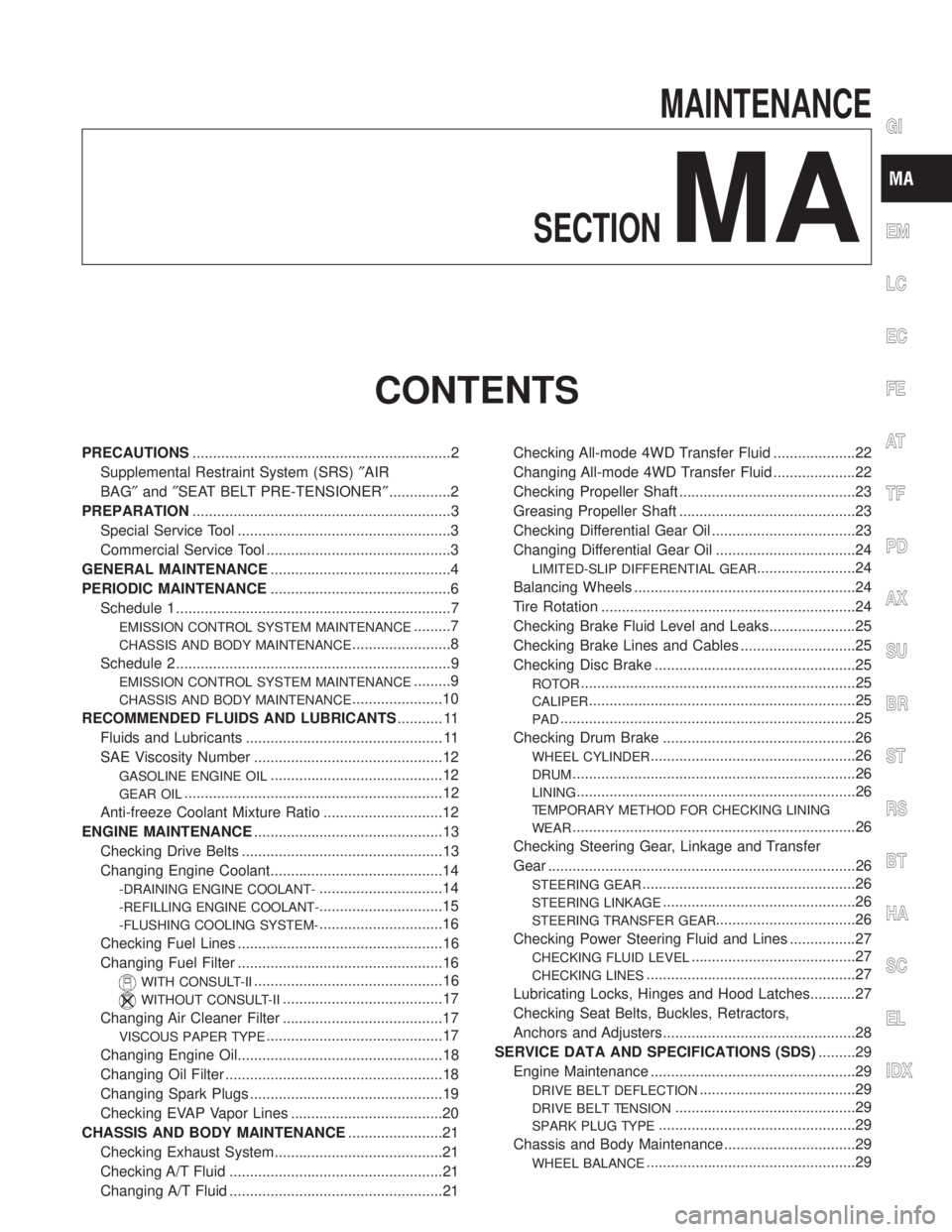
MAINTENANCE
SECTION
MA
CONTENTS
PRECAUTIONS...............................................................2
Supplemental Restraint System (SRS)²AIR
BAG²and²SEAT BELT PRE-TENSIONER²...............2
PREPARATION...............................................................3
Special Service Tool ....................................................3
Commercial Service Tool .............................................3
GENERAL MAINTENANCE............................................4
PERIODIC MAINTENANCE............................................6
Schedule 1 ...................................................................7
EMISSION CONTROL SYSTEM MAINTENANCE.........7
CHASSIS AND BODY MAINTENANCE........................8
Schedule 2 ...................................................................9
EMISSION CONTROL SYSTEM MAINTENANCE.........9
CHASSIS AND BODY MAINTENANCE......................10
RECOMMENDED FLUIDS AND LUBRICANTS........... 11
Fluids and Lubricants ................................................ 11
SAE Viscosity Number ..............................................12
GASOLINE ENGINE OIL..........................................12
GEAR OIL...............................................................12
Anti-freeze Coolant Mixture Ratio .............................12
ENGINE MAINTENANCE..............................................13
Checking Drive Belts .................................................13
Changing Engine Coolant..........................................14
-DRAINING ENGINE COOLANT-..............................14
-REFILLING ENGINE COOLANT-..............................15
-FLUSHING COOLING SYSTEM-..............................16
Checking Fuel Lines ..................................................16
Changing Fuel Filter ..................................................16
WITH CONSULT-II..............................................16
WITHOUT CONSULT-II.......................................17
Changing Air Cleaner Filter .......................................17
VISCOUS PAPER TYPE...........................................17
Changing Engine Oil..................................................18
Changing Oil Filter .....................................................18
Changing Spark Plugs ...............................................19
Checking EVAP Vapor Lines .....................................20
CHASSIS AND BODY MAINTENANCE.......................21
Checking Exhaust System.........................................21
Checking A/T Fluid ....................................................21
Changing A/T Fluid ....................................................21Checking All-mode 4WD Transfer Fluid ....................22
Changing All-mode 4WD Transfer Fluid ....................22
Checking Propeller Shaft ...........................................23
Greasing Propeller Shaft ...........................................23
Checking Differential Gear Oil ...................................23
Changing Differential Gear Oil ..................................24
LIMITED-SLIP DIFFERENTIAL GEAR........................24
Balancing Wheels ......................................................24
Tire Rotation ..............................................................24
Checking Brake Fluid Level and Leaks.....................25
Checking Brake Lines and Cables ............................25
Checking Disc Brake .................................................25
ROTOR...................................................................25
CALIPER.................................................................25
PAD........................................................................25
Checking Drum Brake ...............................................26
WHEEL CYLINDER..................................................26
DRUM.....................................................................26
LINING....................................................................26
TEMPORARY METHOD FOR CHECKING LINING
WEAR
.....................................................................26
Checking Steering Gear, Linkage and Transfer
Gear ...........................................................................26
STEERING GEAR....................................................26
STEERING LINKAGE...............................................26
STEERING TRANSFER GEAR..................................26
Checking Power Steering Fluid and Lines ................27
CHECKING FLUID LEVEL........................................27
CHECKING LINES...................................................27
Lubricating Locks, Hinges and Hood Latches...........27
Checking Seat Belts, Buckles, Retractors,
Anchors and Adjusters...............................................28
SERVICE DATA AND SPECIFICATIONS (SDS).........29
Engine Maintenance ..................................................29
DRIVE BELT DEFLECTION......................................29
DRIVE BELT TENSION............................................29
SPARK PLUG TYPE................................................29
Chassis and Body Maintenance ................................29
WHEEL BALANCE...................................................29
GI
EM
LC
EC
FE
AT
TF
PD
AX
SU
BR
ST
RS
BT
HA
SC
EL
IDX
Page 1997 of 2395
Supplemental Restraint System (SRS) ªAIR
BAGº and ªSEAT BELT PRE-TENSIONERº
NBMA0001The Supplemental Restraint System such as ªAIR BAGº and ªSEAT BELT PRE-TENSIONERº used along with
a seat belt, helps to reduce the risk or severity of injury to the driver and front passenger for certain types of
collision. The SRS system composition which is available to INFINITI QX4 is as follows:
IFor a frontal collision
The Supplemental Restraint System consists of driver air bag module (located in the center of the steer-
ing wheel), front passenger air bag module (located on the instrument panel on passenger side), seat belt
pre-tensioners, a diagnosis sensor unit, warning lamp, wiring harness and spiral cable.
IFor a side collision
The Supplemental Restraint System consists of side air bag module (located in the outer side of front seat),
satellite sensor, diagnosis sensor unit (one of components of air bags for a frontal collision), wiring harness,
warning lamp (one of components of air bags for a frontal collision).
Information necessary to service the system safely is included in theRS sectionof this Service Manual.
WARNING:
ITo avoid rendering the SRS inoperative, which could increase the risk of personal injury or death
in the event of a collision which would result in air bag inflation, all maintenance must be performed
by an authorized INFINITI dealer.
IImproper maintenance, including incorrect removal and installation of the SRS, can lead to per-
sonal injury caused by unintentional activation of the system. For removal of Spiral Cable and Air
Bag Module, see the RS section.
IDo not use electrical test equipment on any circuit related to the SRS unless instructed to in this
Service Manual. Spiral cable and wiring harnesses covered with yellow insulation tape either just
before the harness connectors or for the complete harness are related to the SRS.
PRECAUTIONS
Supplemental Restraint System (SRS) ªAIR BAGº and ªSEAT BELT PRE-TENSIONERº
MA-2
Page 1998 of 2395

Special Service ToolNBMA0002The actual shapes of Kent-Moore tools may differ from those of special service tools illustrated here.
Tool number
(Kent-Moore No.)
Tool nameDescription
KV10115801
(J38956)
Oil filter cap wrench
NT375
Removing oil filter
a: 64.3 mm (2.531 in)
Commercial Service ToolNBMA0041
Tool name
(Kent-Moore No.)Description
Belt tension gauge
(BT3373-F)
AMA126
Checking drive belt tension
GI
EM
LC
EC
FE
AT
TF
PD
AX
SU
BR
ST
RS
BT
HA
SC
EL
IDX
PREPARATION
Special Service Tool
MA-3