belt INFINITI QX4 2001 Factory Owner's Manual
[x] Cancel search | Manufacturer: INFINITI, Model Year: 2001, Model line: QX4, Model: INFINITI QX4 2001Pages: 2395, PDF Size: 43.2 MB
Page 1679 of 2395

SEM828E
7. Apply engine oil to new valve oil seal and install it with Tool.
SEM715A
OIL SEAL INSTALLATION DIRECTIONNBEM0015S02IInstall new oil seal in the direction shown in the figure.
FRONT OIL SEALNBEM0015S031. Remove the following parts:
IEngine undercover
ISuspension member stay
IDrive belts
ICrankshaft position sensor (REF)
Be careful not to damage sensor edge.
ICrankshaft pulley
IRadiator
ICooling fan
SEM829E
2. Remove front oil seal using a suitable tool.
Be careful not to scratch front cover.
3. Apply engine oil to new oil seal and install it using a suitable
tool.
SEM830E
REAR OIL SEALNBEM0015S041. Remove transmission. Refer to AT-277, ªRemovalº.
2. Remove drive plate.
3. Remove oil pan. Refer to EM-15.
4. Remove rear oil seal retainer.
OIL SEAL
Replacement (Cont'd)
EM-36
Page 1702 of 2395
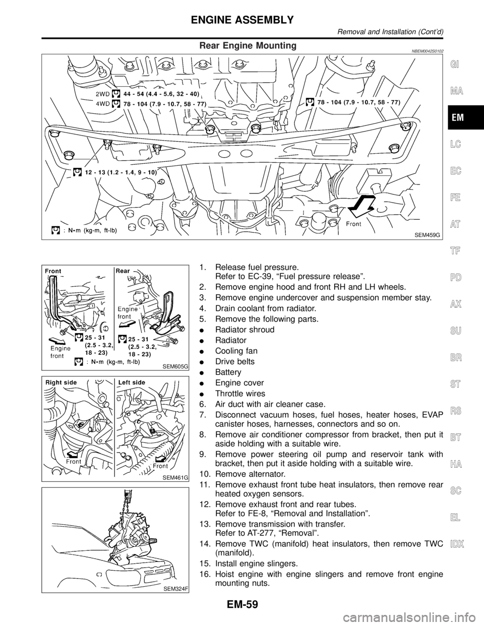
Rear Engine MountingNBEM0042S0102
SEM459G
SEM605G
SEM461G
SEM324F
1. Release fuel pressure.
Refer to EC-39, ªFuel pressure releaseº.
2. Remove engine hood and front RH and LH wheels.
3. Remove engine undercover and suspension member stay.
4. Drain coolant from radiator.
5. Remove the following parts.
IRadiator shroud
IRadiator
ICooling fan
IDrive belts
IBattery
IEngine cover
IThrottle wires
6. Air duct with air cleaner case.
7. Disconnect vacuum hoses, fuel hoses, heater hoses, EVAP
canister hoses, harnesses, connectors and so on.
8. Remove air conditioner compressor from bracket, then put it
aside holding with a suitable wire.
9. Remove power steering oil pump and reservoir tank with
bracket, then put it aside holding with a suitable wire.
10. Remove alternator.
11. Remove exhaust front tube heat insulators, then remove rear
heated oxygen sensors.
12. Remove exhaust front and rear tubes.
Refer to FE-8, ªRemoval and Installationº.
13. Remove transmission with transfer.
Refer to AT-277, ªRemovalº.
14. Remove TWC (manifold) heat insulators, then remove TWC
(manifold).
15. Install engine slingers.
16. Hoist engine with engine slingers and remove front engine
mounting nuts.
GI
MA
LC
EC
FE
AT
TF
PD
AX
SU
BR
ST
RS
BT
HA
SC
EL
IDX
ENGINE ASSEMBLY
Removal and Installation (Cont'd)
EM-59
Page 1745 of 2395
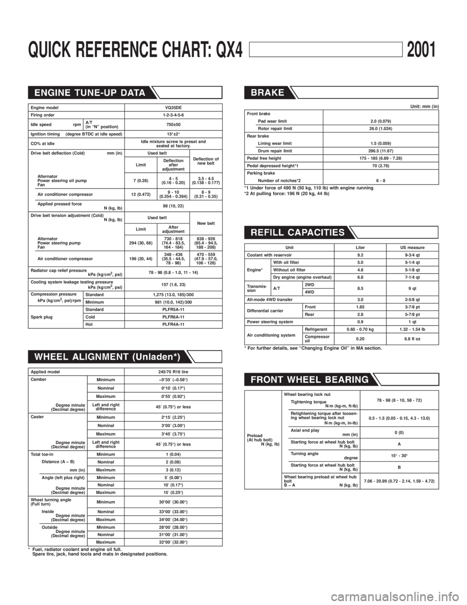
QUICK REFERENCE CHART: QX42001
Engine model VQ35DE
Firing order 1-2-3-4-5-6
Idle speed rpmA/T
(in ªNº position)750 50
Ignition timing (degree BTDC at idle speed) 15É 2É
CO% at idleIdle mixture screw is preset and
sealed at factory.
Drive belt deflection (Cold) mm (in) Used belt
Deflection of
new belt
LimitDeflection
after
adjustment
Alternator
Power steering oil pump
Fan7 (0.28)4-5
(0.16 - 0.20)3.5 - 4.5
(0.138 - 0.177)
Air conditioner compressor 12 (0.472)9-10
(0.354 - 0.394)8-9
(0.31 - 0.35)
Applied pressed force
N (kg, lb)98 (10, 22)
Drive belt tension adjustment (Cold)
N (kg, lb)Used belt
New belt
LimitAfter
adjustment
Alternator
Power steering pump
Fan294 (30, 66)730 - 818
(74.4 - 83.5,
164 - 184)838 - 926
(85.4 - 94.5,
188 - 208)
Air conditioner compressor 196 (20, 44)348 - 436
(35.5 - 44.5,
78 - 98)470 - 559
(47.9 - 57.0,
106 - 126)
Radiator cap relief pressure
kPa (kg/cm
2, psi)78 - 98 (0.8 - 1.0, 11 - 14)
Cooling system leakage testing pressure
kPa (kg/cm
2, psi)157 (1.6, 23)
Compression pressure
kPa (kg/cm
2, psi)/rpmStandard 1,275 (13.0, 185)/300
Minimum 981 (10.0, 142)/300
Spark plugStandard PLFR5A-11
Cold PLFR6A-11
Hot PLFR4A-11
Applied model 245/70 R16 tire
Camber
Degree minute
(Decimal degree)Minimum þ0É35¢(þ0.58É)
Nominal 0É10¢(0.17É)
Maximum 0É55¢(0.92É)
Left and right
difference45¢(0.75É) or less
Caster
Degree minute
(Decimal degree)Minimum 2É15¢(2.25É)
Nominal 3É00¢(3.00É)
Maximum 3É45¢(3.75É)
Left and right
difference45¢(0.75É) or less
Total toe-in Minimum 1 (0.04)
Distance (A þ B)
mm (in)Nominal 2 (0.08)
Maximum 3 (0.12)
Angle (left plus right)
Degree minute
(Decimal degree)Minimum 5¢(0.08É)
Nominal 10¢(0.17É)
Maximum 15¢(0.25É)
Wheel turning angle
(Full turn)Minimum 30É00¢(30.00É)
Inside
Degree minute
(Decimal degree)Nominal 33É00¢(33.00É)
Maximum 34É00¢(34.00É)
Outside
Degree minute
(Decimal degree)Minimum 28É00¢(28.00É)
Nominal 31É00¢(31.00É)
Maximum 32É00¢(32.00É)
* Fuel, radiator coolant and engine oil full.
Spare tire, jack, hand tools and mats in designated positions.
Unit: mm (in)Front brake
Pad wear limit 2.0 (0.079)
Rotor repair limit 26.0 (1.024)
Rear brake
Lining wear limit 1.5 (0.059)
Drum repair limit 296.5 (11.67)
Pedal free height 175 - 185 (6.89 - 7.28)
Pedal depressed height*1 70 (2.76)
Parking brake
Number of notches*2 6 - 8
*1 Under force of 490 N (50 kg, 110 lb) with engine running
*2 At pulling force: 196 N (20 kg, 44 lb)
Unit Liter US measure
Coolant with reservoir 9.2 9-3/4 qt
Engine*With oil filter 5.0 5-1/4 qt
Without oil filter 4.8 5-1/8 qt
Dry engine (engine overhaul) 6.8 7-1/4 qt
Transmis-
sionA/T2WD
8.5 9 qt
4WD
All-mode 4WD transfer 3.0 2-5/8 qt
Differential carrierFront 1.85 3-7/8 pt
Rear 2.8 5-7/8 pt
Power steering system 0.9 1 qt
Air conditioning systemRefrigerant 0.60 - 0.70 kg 1.32 - 1.54 lb
Compressor
oil0.20 6.8 fl oz
* For further details, see ªChanging Engine Oilº in MA section.
Preload
(At hub bolt)
N (kg, lb)Wheel bearing lock nut
78-98(8-10,58-72)
Tightening torque
N×m (kg-m, ft-lb)
Retightening torque after loosen-
ing wheel bearing lock nut
N×m (kg-m, in-lb)0.5 - 1.5 (0.05 - 0.15, 4.3 - 13.0)
Axial end play
mm (in)0 (0)
Starting force at wheel hub bolt
N (kg, lb)A
Turning angle
degree15É - 30É
Starting force at wheel hub bolt
N (kg, lb)B
Wheel bearing preload at wheel hub
bolt
B þ A N (kg, lb)7.06 - 20.99 (0.72 - 2.14, 1.59 - 4.72)
Page 1746 of 2395
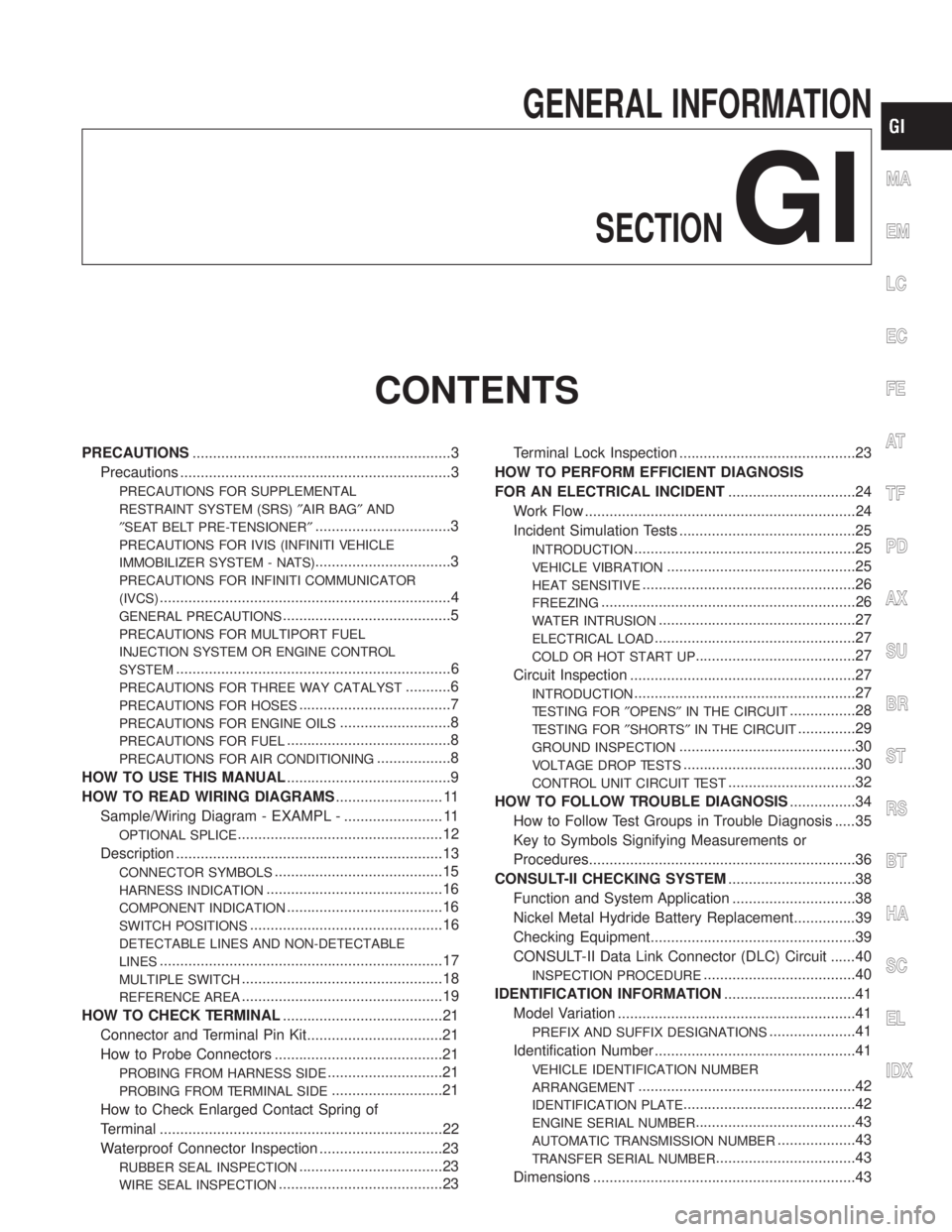
GENERAL INFORMATION
SECTION
GI
CONTENTS
PRECAUTIONS...............................................................3
Precautions ..................................................................3
PRECAUTIONS FOR SUPPLEMENTAL
RESTRAINT SYSTEM (SRS)²AIR BAG²AND
²SEAT BELT PRE-TENSIONER²
.................................3
PRECAUTIONS FOR IVIS (INFINITI VEHICLE
IMMOBILIZER SYSTEM - NATS)
.................................3
PRECAUTIONS FOR INFINITI COMMUNICATOR
(IVCS)
.......................................................................4
GENERAL PRECAUTIONS.........................................5
PRECAUTIONS FOR MULTIPORT FUEL
INJECTION SYSTEM OR ENGINE CONTROL
SYSTEM
...................................................................6
PRECAUTIONS FOR THREE WAY CATALYST...........6
PRECAUTIONS FOR HOSES.....................................7
PRECAUTIONS FOR ENGINE OILS...........................8
PRECAUTIONS FOR FUEL........................................8
PRECAUTIONS FOR AIR CONDITIONING..................8
HOW TO USE THIS MANUAL........................................9
HOW TO READ WIRING DIAGRAMS.......................... 11
Sample/Wiring Diagram - EXAMPL - ........................ 11
OPTIONAL SPLICE..................................................12
Description .................................................................13
CONNECTOR SYMBOLS.........................................15
HARNESS INDICATION...........................................16
COMPONENT INDICATION......................................16
SWITCH POSITIONS...............................................16
DETECTABLE LINES AND NON-DETECTABLE
LINES
.....................................................................17
MULTIPLE SWITCH.................................................18
REFERENCE AREA.................................................19
HOW TO CHECK TERMINAL.......................................21
Connector and Terminal Pin Kit.................................21
How to Probe Connectors .........................................21
PROBING FROM HARNESS SIDE............................21
PROBING FROM TERMINAL SIDE...........................21
How to Check Enlarged Contact Spring of
Terminal .....................................................................22
Waterproof Connector Inspection ..............................23
RUBBER SEAL INSPECTION...................................23
WIRE SEAL INSPECTION........................................23Terminal Lock Inspection ...........................................23
HOW TO PERFORM EFFICIENT DIAGNOSIS
FOR AN ELECTRICAL INCIDENT...............................24
Work Flow ..................................................................24
Incident Simulation Tests ...........................................25
INTRODUCTION......................................................25
VEHICLE VIBRATION..............................................25
HEAT SENSITIVE....................................................26
FREEZING..............................................................26
WATER INTRUSION................................................27
ELECTRICAL LOAD.................................................27
COLD OR HOT START UP.......................................27
Circuit Inspection .......................................................27
INTRODUCTION......................................................27
TESTING FOR²OPENS²IN THE CIRCUIT................28
TESTING FOR²SHORTS²IN THE CIRCUIT..............29
GROUND INSPECTION...........................................30
VOLTAGE DROP TESTS..........................................30
CONTROL UNIT CIRCUIT TEST...............................32
HOW TO FOLLOW TROUBLE DIAGNOSIS................34
How to Follow Test Groups in Trouble Diagnosis .....35
Key to Symbols Signifying Measurements or
Procedures.................................................................36
CONSULT-II CHECKING SYSTEM...............................38
Function and System Application ..............................38
Nickel Metal Hydride Battery Replacement...............39
Checking Equipment..................................................39
CONSULT-II Data Link Connector (DLC) Circuit ......40
INSPECTION PROCEDURE.....................................40
IDENTIFICATION INFORMATION................................41
Model Variation ..........................................................41
PREFIX AND SUFFIX DESIGNATIONS.....................41
Identification Number .................................................41
VEHICLE IDENTIFICATION NUMBER
ARRANGEMENT
.....................................................42
IDENTIFICATION PLATE..........................................42
ENGINE SERIAL NUMBER.......................................43
AUTOMATIC TRANSMISSION NUMBER...................43
TRANSFER SERIAL NUMBER..................................43
Dimensions ................................................................43
MA
EM
LC
EC
FE
AT
TF
PD
AX
SU
BR
ST
RS
BT
HA
SC
EL
IDX
Page 1748 of 2395

PrecautionsNBGI0001Observe the following precautions to ensure safe and proper
servicing. These precautions are not described in each indi-
vidual section.
SGI646
PRECAUTIONS FOR SUPPLEMENTAL RESTRAINT
SYSTEM (SRS) ªAIR BAGº AND ªSEAT BELT
PRE-TENSIONERº
NBGI0001S01The Supplemental Restraint System such as ªAIR BAGº and ªSEAT
BELT PRE-TENSIONERº used along with a seat belt, helps to
reduce the risk or severity of injury to the driver and front passen-
ger for certain types of collision. The SRS system composition
which is available to INFINITI QX4 is as follows:
IFor a frontal collision
The Supplemental Restraint System consists of driver air bag
module (located in the center of the steering wheel), front pas-
senger air bag module (located on the instrument panel on
passenger side), seat belt pre-tensioners, a diagnosis sensor
unit, warning lamp, wiring harness and spiral cable.
IFor a side collision
The Supplemental Restraint System consists of side air bag
module (located in the outer side of front seat), satellite sensor,
diagnosis sensor unit (one of components of air bags for a
frontal collision), wiring harness, warning lamp (one of compo-
nents of air bags for a frontal collision).
Information necessary to service the system safely is included in
theRS sectionof this Service Manual.
WARNING:
ITo avoid rendering the SRS inoperative, which could
increase the risk of personal injury or death in the event
of a collision which would result in air bag inflation, all
maintenance must be performed by an authorized INFINITI
dealer.
IImproper maintenance, including incorrect removal and
installation of the SRS, can lead to personal injury caused
by unintentional activation of the system. For removal of
Spiral Cable and Air Bag Module, see the RS section.
IDo not use electrical test equipment on any circuit related
to the SRS unless instructed to in this Service Manual.
Spiral cable and wiring harnesses covered with yellow
insulation tape either just before the harness connectors
or for the complete harness are related to the SRS.
PRECAUTIONS FOR IVIS (INFINITI VEHICLE
IMMOBILIZER SYSTEM Ð NATS)
NBGI0001S08IVIS (NATS) will immobilize the engine if someone tries to start it
without the registered key of IVIS (NATS).
Both of the originally supplied ignition key IDs have been IVIS
(NATS) registered.
MA
EM
LC
EC
FE
AT
TF
PD
AX
SU
BR
ST
RS
BT
HA
SC
EL
IDX
PRECAUTIONS
Precautions
GI-3
Page 1800 of 2395
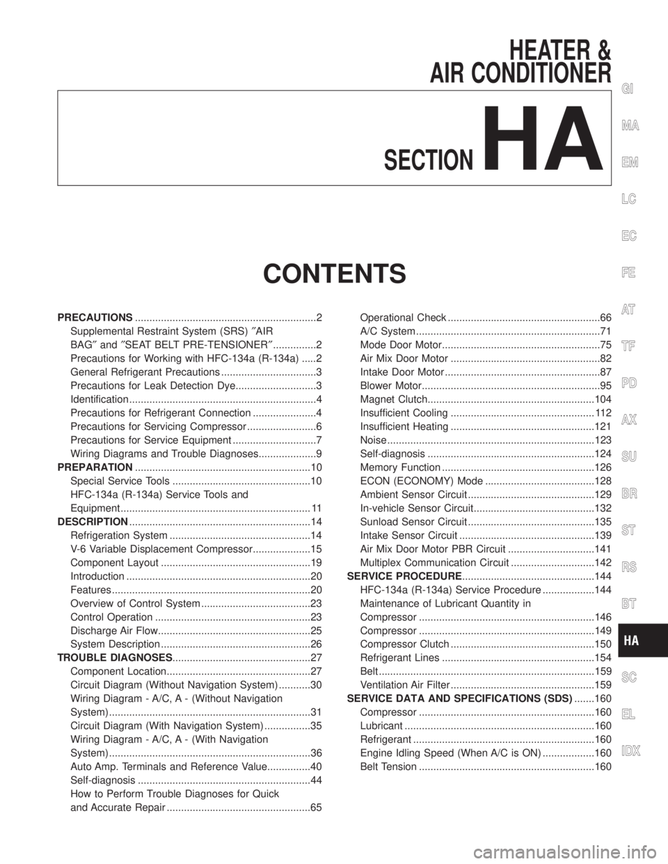
HEATER &
AIR CONDITIONER
SECTION
HA
CONTENTS
PRECAUTIONS...............................................................2
Supplemental Restraint System (SRS)²AIR
BAG²and²SEAT BELT PRE-TENSIONER²...............2
Precautions for Working with HFC-134a (R-134a) .....2
General Refrigerant Precautions .................................3
Precautions for Leak Detection Dye............................3
Identification .................................................................4
Precautions for Refrigerant Connection ......................4
Precautions for Servicing Compressor ........................6
Precautions for Service Equipment .............................7
Wiring Diagrams and Trouble Diagnoses....................9
PREPARATION.............................................................10
Special Service Tools ................................................10
HFC-134a (R-134a) Service Tools and
Equipment .................................................................. 11
DESCRIPTION...............................................................14
Refrigeration System .................................................14
V-6 Variable Displacement Compressor....................15
Component Layout ....................................................19
Introduction ................................................................20
Features .....................................................................20
Overview of Control System ......................................23
Control Operation ......................................................23
Discharge Air Flow.....................................................25
System Description ....................................................26
TROUBLE DIAGNOSES................................................27
Component Location..................................................27
Circuit Diagram (Without Navigation System) ...........30
Wiring Diagram - A/C, A - (Without Navigation
System) ......................................................................31
Circuit Diagram (With Navigation System) ................35
Wiring Diagram - A/C, A - (With Navigation
System) ......................................................................36
Auto Amp. Terminals and Reference Value...............40
Self-diagnosis ............................................................44
How to Perform Trouble Diagnoses for Quick
and Accurate Repair ..................................................65Operational Check .....................................................66
A/C System ................................................................71
Mode Door Motor.......................................................75
Air Mix Door Motor ....................................................82
Intake Door Motor ......................................................87
Blower Motor..............................................................95
Magnet Clutch..........................................................104
Insufficient Cooling .................................................. 112
Insufficient Heating ..................................................121
Noise ........................................................................123
Self-diagnosis ..........................................................124
Memory Function .....................................................126
ECON (ECONOMY) Mode ......................................128
Ambient Sensor Circuit ............................................129
In-vehicle Sensor Circuit..........................................132
Sunload Sensor Circuit ............................................135
Intake Sensor Circuit ...............................................139
Air Mix Door Motor PBR Circuit ..............................141
Multiplex Communication Circuit .............................142
SERVICE PROCEDURE..............................................144
HFC-134a (R-134a) Service Procedure ..................144
Maintenance of Lubricant Quantity in
Compressor .............................................................146
Compressor .............................................................149
Compressor Clutch ..................................................150
Refrigerant Lines .....................................................154
Belt ...........................................................................159
Ventilation Air Filter ..................................................159
SERVICE DATA AND SPECIFICATIONS (SDS).......160
Compressor .............................................................160
Lubricant ..................................................................160
Refrigerant ...............................................................160
Engine Idling Speed (When A/C is ON) ..................160
Belt Tension .............................................................160
GI
MA
EM
LC
EC
FE
AT
TF
PD
AX
SU
BR
ST
RS
BT
SC
EL
IDX
Page 1801 of 2395
Supplemental Restraint System (SRS) ªAIR
BAGº and ªSEAT BELT PRE-TENSIONERº
NBHA0001The Supplemental Restraint System such as ªAIR BAGº and ªSEAT BELT PRE-TENSIONERº used along with
a seat belt, helps to reduce the risk or severity of injury to the driver and front passenger for certain types of
collision. The SRS system composition which is available to INFINITI QX4 is as follows:
IFor a frontal collision
The Supplemental Restraint System consists of driver air bag module (located in the center of the steer-
ing wheel), front passenger air bag module (located on the instrument panel on passenger side), seat belt
pre-tensioners, a diagnosis sensor unit, warning lamp, wiring harness and spiral cable.
IFor a side collision
The Supplemental Restraint System consists of front side air bag module (located in the outer side of front
seat), satellite sensor, diagnosis sensor unit (one of components of air bags for a frontal collision), wiring
harness, warning lamp (one of components of air bags for a frontal collision).
Information necessary to service the system safely is included in theRS sectionof this Service Manual.
WARNING:
ITo avoid rendering the SRS inoperative, which could increase the risk of personal injury or death
in the event of a collision which would result in air bag inflation, all maintenance must be performed
by an authorized INFINITI dealer.
IImproper maintenance, including incorrect removal and installation of the SRS, can lead to per-
sonal injury caused by unintentional activation of the system. For removal of Spiral Cable and Air
Bag Module, see the RS section.
IDo not use electrical test equipment on any circuit related to the SRS unless instructed to in this
Service Manual. Spiral cable and wiring harnesses covered with yellow insulation tape either just
before the harness connectors or for the complete harness are related to the SRS.
Precautions for Working with HFC-134a
(R-134a)
NBHA0002WARNING:
ICFC-12 (R-12) refrigerant and HFC-134a (R-134a) refrigerant are not compatible. If the refrigerants
are mixed and compressor failure is likely to occur, refer to ªCONTAMINATED REFRIGERANTº
below. To determine the purity of HFC-134a (R-134a) in the vehicle and recovery tank, use Refrig-
erant Recovery/Recycling Recharging equipment (ACR4) (J-39500-INF) and Refrigerant Identifier.
IUse only specified lubricant for the HFC-134a (R-134a) A/C system and HFC-134a (R-134a) compo-
nents. If lubricant other than that specified is used, compressor failure is likely to occur.
IThe specified HFC-134a (R-134a) lubricant rapidly absorbs moisture from the atmosphere. The fol-
lowing handling precautions must be observed:
a) When removing refrigerant components from a vehicle, immediately cap (seal) the component to
minimize the entry of moisture from the atmosphere.
b) When installing refrigerant components to a vehicle, do not remove the caps (unseal) until just
before connecting the components. Connect all refrigerant loop components as quickly as pos-
sible to minimize the entry of moisture into system.
c) Only use the specified lubricant from a sealed container. Immediately reseal containers of lubri-
cant. Without proper sealing, lubricant will become moisture saturated and should not be used.
d) Avoid breathing A/C refrigerant and lubricant vapor or mist. Exposure may irritate eyes, nose and
throat. Remove R-134a from the A/C system, using certified service equipment meeting require-
ments of SAE J2210 (R-134a recycling equipment), or J2209 (R-134a recovery equipment). If acci-
dental system discharge occurs, ventilate work area before resuming service. Additional health and
safety information may be obtained from refrigerant and lubricant manufacturers.
e) Do not allow lubricant (Nissan A/C System Oil Type S) to come in contact with styrofoam parts.
Damage may result.
CONTAMINATED REFRIGERANTNBHA0002S01If a refrigerant other than pure R-134a is identified in a vehicle, your options are:
IExplain to the customer that environmental regulations prohibit the release of contaminated refrigerant into
the atmosphere.
IExplain that recovery of the contaminated refrigerant could damage your service equipment and refriger-
ant supply.
PRECAUTIONS
Supplemental Restraint System (SRS) ªAIR BAGº and ªSEAT BELT PRE-TENSIONERº
HA-2
Page 1958 of 2395

Belt
TENSION ADJUSTMENTNBHA0079IRefer to MA-13, ªChecking Drive Beltsº.
RHA042G
Ventilation Air Filter
FUNCTIONNBHA0108Air inside passenger compartment is kept clean at either recircula-
tion or fresh mode by installing ventilation air filter into cooling unit.
NOTE:
To replace ventilation air filter, refer to MA-6, ªPeriodic Main-
tenanceº.
Caution label is fixed inside the glove box.
SHA252F
REPLACEMENT PROCEDURENBHA01091. Remove glove box.
2. Remove instrument lower panel from instrument panel.
3. Remove ventilation air filter fixed clip.
SHA253F
4. Take out the lower side ventilation air filter from cooling unit.
5. Then slide upper side filter to the bottom position and take off
the ventilation air filter from the cooling unit.
6. Replace with new one and reinstall on cooling unit.
7. Reinstall clip, instrument lower panel and glove box.
GI
MA
EM
LC
EC
FE
AT
TF
PD
AX
SU
BR
ST
RS
BT
SC
EL
IDX
SERVICE PROCEDURE
Belt
HA-159
Page 1959 of 2395

CompressorNBHA0081
ModelCALSONIC make V-6
TypeV-6 variable displacement
Displacement
cm
3(cu in)/rev.Max. 184 (11.228)
Min. 14.5 (0.885)
Cylinder bore x stroke
mm (in)37 (1.46) x [2.3 - 28.6 (0.091 - 1.126)]
Direction of rotationClockwise (viewed from drive end)
Drive beltPoly V
LubricantNBHA0082
ModelCALSONIC make V-6
NameNissan A/C System Oil Type S
Part number*KLH00-PAGS0
Capacity
m(US fl oz, Imp fl oz)Total in system 200 (6.8, 7.0)
Compressor (Service part) charging amount 200 (6.8, 7.0)
*: Always check with the Parts Department for the latest parts information.
RefrigerantNBHA0083
TypeHFC-134a (R-134a)
Capacity
kg (lb)0.60 - 0.70 (1.32 - 1.54)
Engine Idling Speed (When A/C is ON)NBHA0084IRefer to EC-649, ªIdle Speed and Ignition Timingº.
Belt TensionNBHA0085IRefer to MA-29, ªEngine Maintenanceº.
SERVICE DATA AND SPECIFICATIONS (SDS)
Compressor
HA-160
Page 1962 of 2395
Brake fluid change ...........................................BR-7
Brake fluid level .............................................MA-25
Brake fluid level and line check .......................BR-7
Brake hydraulic line ..........................................BR-9
Brake inspection ............................................MA-25
Brake lines and cables inspection .................MA-25
Brake lining wear temporary checking ..........MA-26
Brake master cylinder ....................................BR-16
Brake pedal ....................................................BR-14
Bulb specifications ........................................EL-456
Bumper, front ..................................................BT-12
Bumper, rear ...................................................BT-15
BYPS/V - Wiring diagram ....................EC-587, 594
C
Camshaft inspection ......................................EM-42
Camshaft position sensor (PHASE) .............EC-342
Canister-See EVAP canister ..........................EC-32
Center bearing assembly (propeller
shaft) .............................................................PD-9
Center bearing disassembly (propeller
shaft) .............................................................PD-7
Center case (Transfer) ..................................TF-123
CHARGE - Wiring diagram ............................SC-20
Charging system ............................................SC-19
Chassis and body maintenance ....................MA-21
CHIME - Wiring diagram...............................EL-127
CIGAR - Wiring diagram ...............................EL-148
Cigarette lighter.............................................EL-148
Circuit breaker.................................................EL-16
CKPS - Wiring diagram ................................EC-334
Closed loop control (Left bank) ....................EC-491
Closed loop control (Right bank) .................EC-491
Closed throttle position switch .....................EC-431
Clutch drum (Transfer) ..................................TF-125
Clutch force release limit adjustment .............TF-39
Clutch pressure switch (Transfer) .................TF-111
Coil spring (front)..............................................SU-8
Coil spring (rear) ............................................SU-18
Collision diagnosis..........................................RS-59
Combination lamp, front, removal and
installation ...................................................BT-12
Combination lamp, rear, removal and
installation ...................................................BT-35
Combination meter..........................................EL-94
Combination meter removal and instal-
lation - See Instrument panel ......................BT-21
Combination switch .........................................EL-28
COMPAS - Wiring diagram ...........................EL-111
Compass .......................................................EL-110
Component Location (auto A/C).....................HA-27
Compression pressure ...................................EM-14
Compressor clutch removal and
installation .................................................HA-150
Compressor precaution ....................................HA-6
Compressor special service tool ....................HA-10
Connecting rod...............................................EM-65
Connecting rod bearing clearance.................EM-69
Connecting rod bushing clearance ................EM-70Connector inspection .......................................GI-21
Console box - See Instrument panel ..............BT-21
CONSULT for ABS .........................................BR-43
CONSULT for all-mode 4WD ..........................TF-30
CONSULT for engine .....................................EC-81
CONSULT-II general information .....................GI-38
Control valve (A/T) ........................................AT-301
Control valve (Transfer) ................................TF-128
Converter housing installation .......................AT-278
Coolant mixture ratio......................................MA-12
Coolant replacement ......................................MA-14
Cooling circuit (engine) ...................................LC-10
``Crankcase emission control system -
See positive crankcase ventilation''............EC-38
Crankshaft ......................................................EM-67
Crankshaft position sensor (POS) ...............EC-334
Crankshaft position sensor (POS)
chipping ....................................................EC-517
Crankshaft position sensor (REF) ................EC-510
Cruise control - See ASCD ...........................EL-221
Cylinder block ................................................EM-61
Cylinder head .................................................EM-38
Cylinder head bolt tightening .........................EM-49
D
Data link connector for Consult......................EC-81
Daytime light system.......................................EL-46
Daytime running light - See Daytime
light system .................................................EL-46
DEF - Wiring diagram ...................................EL-153
Detonation sensor - See Knock sensor .......EC-328
Diagnostic trouble code (DTC) for OBD
system ....................................................EC-8, 60
Diagnostic trouble code (DTC) inspec-
tion priority chart .......................................EC-116
Differential carrier assembly.....................PD-30, 57
Differential carrier disassembly ......................PD-44
Differential gear oil replacement ....................MA-24
Dimensions ......................................................GI-43
D/LOCK - Wiring diagram .............................EL-256
Dome light - See Interior lamp .......................EL-88
Door glass .......................................................BT-18
Door lock .........................................................BT-18
Door mirror ......................................................BT-56
Door trim .........................................................BT-30
Door, front .......................................................BT-18
Door, rear ........................................................BT-20
Drive belt inspection ......................................MA-13
Drive chain (Transfer) ...................................TF-125
Drive pinion diff. inspection ......................PD-23, 47
Drive pinion height ...................................PD-25, 53
Drive plate runout ..........................................EM-70
Drive shaft (front)............................................AX-10
Dropping resistor (A/T) ..................................AT-167
DTC work support ..........................................EC-93
DTRL - Wiring diagram ...................................EL-51
GI
MA
EM
LC
EC
FE
AT
TF
PD
AX
SU
BR
ST
RS
BT
HA
SC
EL
ALPHABETICAL INDEX
IDX-3