driver seat adjustment INFINITI QX4 2001 Factory Service Manual
[x] Cancel search | Manufacturer: INFINITI, Model Year: 2001, Model line: QX4, Model: INFINITI QX4 2001Pages: 2395, PDF Size: 43.2 MB
Page 1259 of 2395

SEL350X
Aiming AdjustmentNBEL0029Before performing aiming adjustment, make sure of the following.
1) Keep all tires inflated to correct pressure.
2) Place vehicle on level ground.
3) See that vehicle is unloaded (except for full levels of coolant,
engine oil and fuel, and spare tire, jack, and tools). Have the
driver or equivalent weight placed in driver's seat.
Adjust aiming in the vertical direction by turning the adjusting
screw.
MEL327G
1. Set the distance between the screen and the center of the fog
lamp lens as shown at left.
2. Turn front fog lamps ON.
MEL328GA
3. Adjust front fog lamps so that the top edge of the high inten-
sity zone is 200 mm (7.9 in) below the height of the fog lamp
centers as shown at left.
IWhen performing adjustment, if necessary, cover the head-
lamps and opposite fog lamp.
FRONT FOG LAMP
Aiming Adjustment
EL-74
Page 2049 of 2395

AdjustmentNBPD0020For quiet and reliable final drive operation, the following five adjust-
ments must be made correctly:
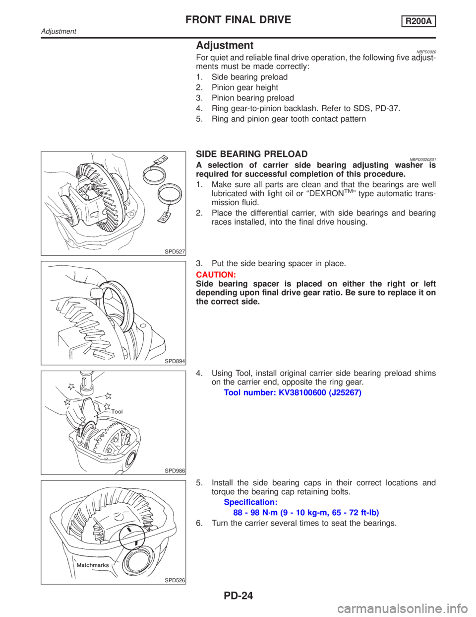
1. Side bearing preload
2. Pinion gear height
3. Pinion bearing preload
4. Ring gear-to-pinion backlash. Refer to SDS, PD-37.
5. Ring and pinion gear tooth contact pattern
SPD527
SIDE BEARING PRELOADNBPD0020S01A selection of carrier side bearing adjusting washer is
required for successful completion of this procedure.
1. Make sure all parts are clean and that the bearings are well
lubricated with light oil or ªDEXRON
TMº type automatic trans-
mission fluid.
2. Place the differential carrier, with side bearings and bearing
races installed, into the final drive housing.
SPD894
3. Put the side bearing spacer in place.
CAUTION:
Side bearing spacer is placed on either the right or left
depending upon final drive gear ratio. Be sure to replace it on
the correct side.
SPD986
4. Using Tool, install original carrier side bearing preload shims
on the carrier end, opposite the ring gear.
Tool number: KV38100600 (J25267)
SPD526
5. Install the side bearing caps in their correct locations and
torque the bearing cap retaining bolts.
Specification:
88 - 98 N´m (9 - 10 kg-m, 65 - 72 ft-lb)
6. Turn the carrier several times to seat the bearings.
FRONT FINAL DRIVER200A
Adjustment
PD-24
Page 2050 of 2395

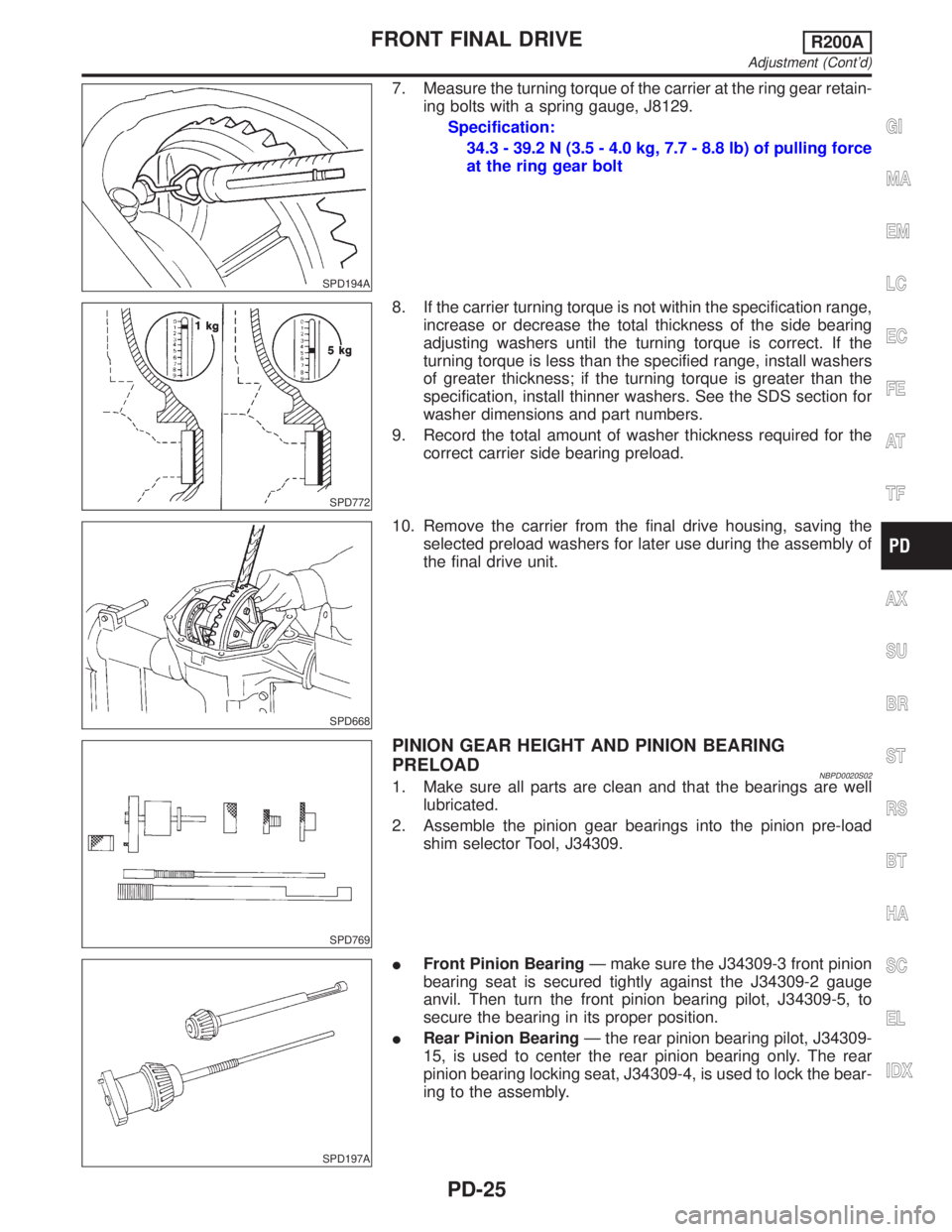
SPD194A
7. Measure the turning torque of the carrier at the ring gear retain-
ing bolts with a spring gauge, J8129.
Specification:
34.3 - 39.2 N (3.5 - 4.0 kg, 7.7 - 8.8 lb) of pulling force
at the ring gear bolt
SPD772
8. If the carrier turning torque is not within the specification range,
increase or decrease the total thickness of the side bearing
adjusting washers until the turning torque is correct. If the
turning torque is less than the specified range, install washers
of greater thickness; if the turning torque is greater than the
specification, install thinner washers. See the SDS section for
washer dimensions and part numbers.
9. Record the total amount of washer thickness required for the
correct carrier side bearing preload.
SPD668
10. Remove the carrier from the final drive housing, saving the
selected preload washers for later use during the assembly of
the final drive unit.
SPD769
PINION GEAR HEIGHT AND PINION BEARING
PRELOAD
NBPD0020S021. Make sure all parts are clean and that the bearings are well
lubricated.
2. Assemble the pinion gear bearings into the pinion pre-load
shim selector Tool, J34309.
SPD197A
IFront Pinion BearingÐ make sure the J34309-3 front pinion
bearing seat is secured tightly against the J34309-2 gauge
anvil. Then turn the front pinion bearing pilot, J34309-5, to
secure the bearing in its proper position.
IRear Pinion BearingÐ the rear pinion bearing pilot, J34309-
15, is used to center the rear pinion bearing only. The rear
pinion bearing locking seat, J34309-4, is used to lock the bear-
ing to the assembly.
GI
MA
EM
LC
EC
FE
AT
TF
AX
SU
BR
ST
RS
BT
HA
SC
EL
IDX
FRONT FINAL DRIVER200A
Adjustment (Cont'd)
PD-25
Page 2051 of 2395

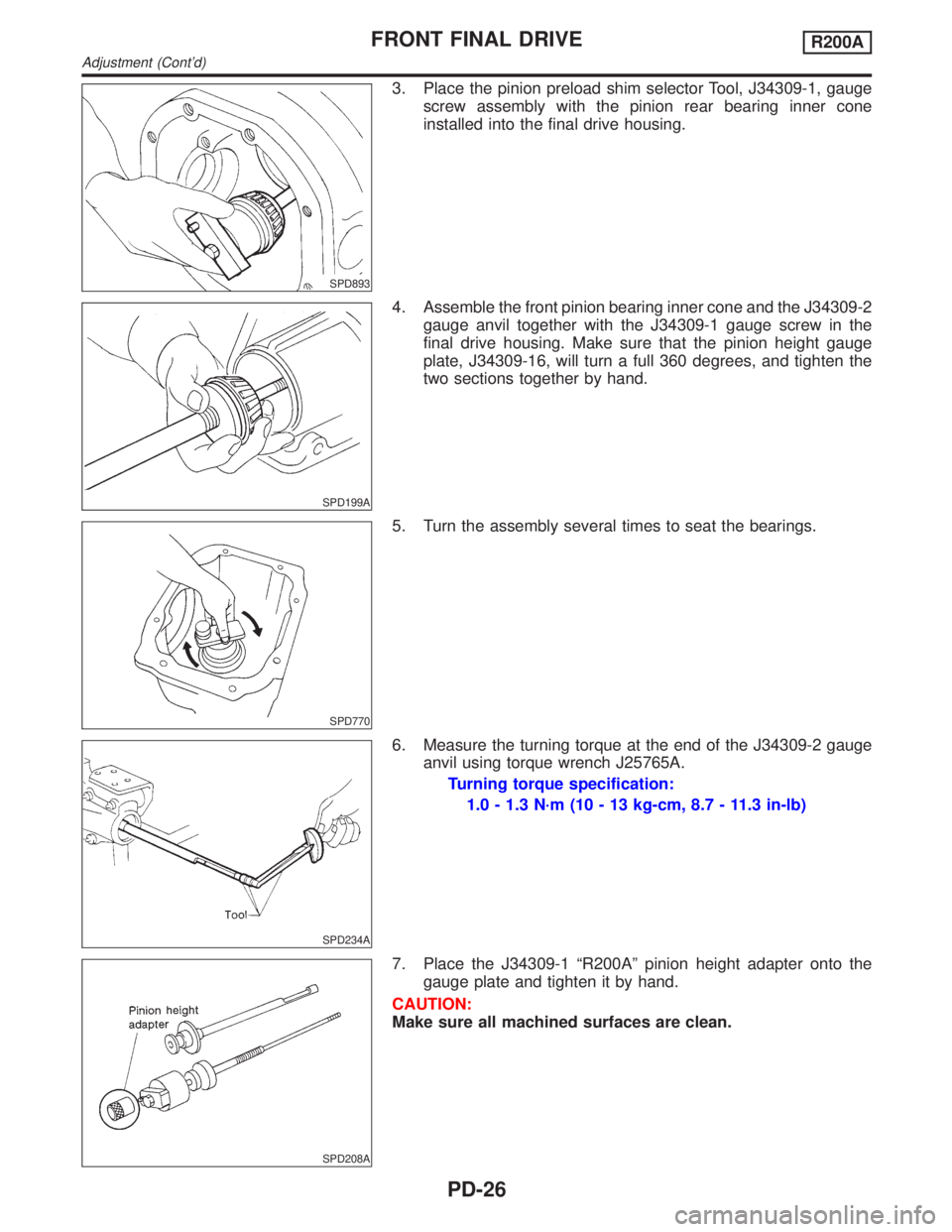
SPD893
3. Place the pinion preload shim selector Tool, J34309-1, gauge
screw assembly with the pinion rear bearing inner cone
installed into the final drive housing.
SPD199A
4. Assemble the front pinion bearing inner cone and the J34309-2
gauge anvil together with the J34309-1 gauge screw in the
final drive housing. Make sure that the pinion height gauge
plate, J34309-16, will turn a full 360 degrees, and tighten the
two sections together by hand.
SPD770
5. Turn the assembly several times to seat the bearings.
SPD234A
6. Measure the turning torque at the end of the J34309-2 gauge
anvil using torque wrench J25765A.
Turning torque specification:
1.0 - 1.3 N´m (10 - 13 kg-cm, 8.7 - 11.3 in-lb)
SPD208A
7. Place the J34309-1 ªR200Aº pinion height adapter onto the
gauge plate and tighten it by hand.
CAUTION:
Make sure all machined surfaces are clean.
FRONT FINAL DRIVER200A
Adjustment (Cont'd)
PD-26
Page 2052 of 2395

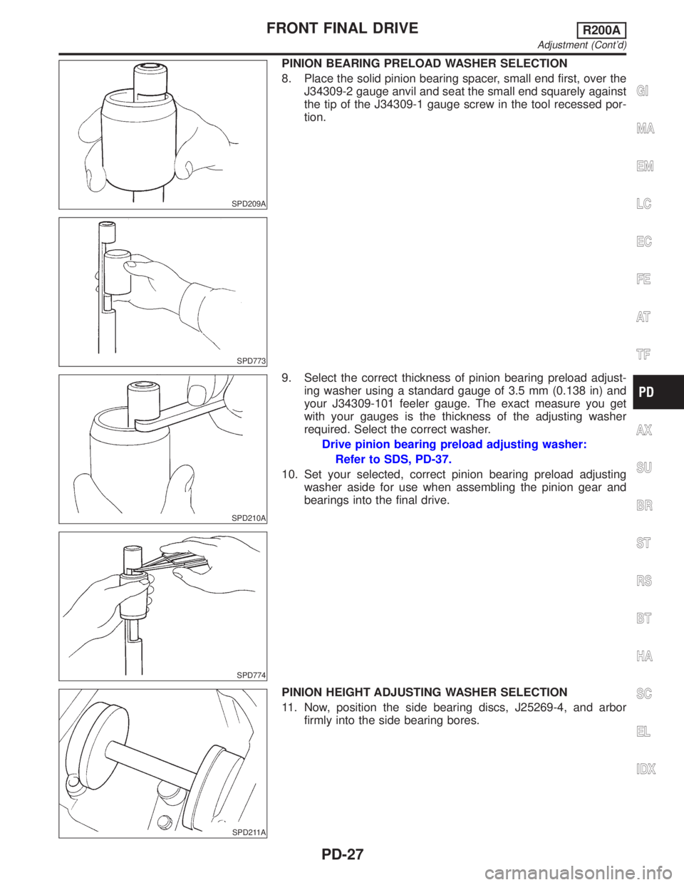
SPD209A
PINION BEARING PRELOAD WASHER SELECTION
8. Place the solid pinion bearing spacer, small end first, over the
J34309-2 gauge anvil and seat the small end squarely against
the tip of the J34309-1 gauge screw in the tool recessed por-
tion.
SPD773
SPD210A
SPD774
9. Select the correct thickness of pinion bearing preload adjust-
ing washer using a standard gauge of 3.5 mm (0.138 in) and
your J34309-101 feeler gauge. The exact measure you get
with your gauges is the thickness of the adjusting washer
required. Select the correct washer.
Drive pinion bearing preload adjusting washer:
Refer to SDS, PD-37.
10. Set your selected, correct pinion bearing preload adjusting
washer aside for use when assembling the pinion gear and
bearings into the final drive.
SPD211A
PINION HEIGHT ADJUSTING WASHER SELECTION
11. Now, position the side bearing discs, J25269-4, and arbor
firmly into the side bearing bores.
GI
MA
EM
LC
EC
FE
AT
TF
AX
SU
BR
ST
RS
BT
HA
SC
EL
IDX
FRONT FINAL DRIVER200A
Adjustment (Cont'd)
PD-27