brake sensor INFINITI QX4 2001 Factory Owner's Manual
[x] Cancel search | Manufacturer: INFINITI, Model Year: 2001, Model line: QX4, Model: INFINITI QX4 2001Pages: 2395, PDF Size: 43.2 MB
Page 391 of 2395
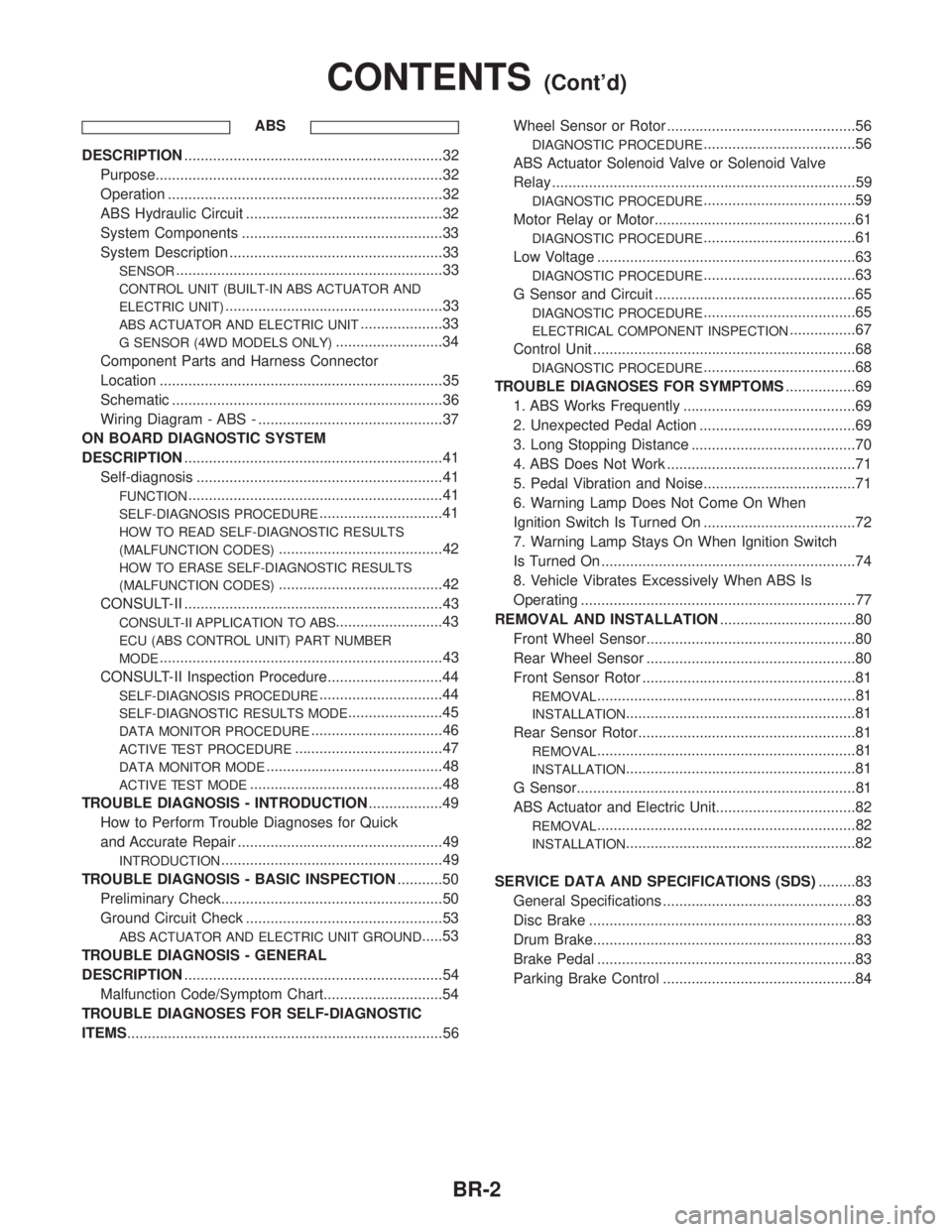
ABS
DESCRIPTION...............................................................32
Purpose......................................................................32
Operation ...................................................................32
ABS Hydraulic Circuit ................................................32
System Components .................................................33
System Description ....................................................33
SENSOR.................................................................33
CONTROL UNIT (BUILT-IN ABS ACTUATOR AND
ELECTRIC UNIT)
.....................................................33
ABS ACTUATOR AND ELECTRIC UNIT....................33
G SENSOR (4WD MODELS ONLY)..........................34
Component Parts and Harness Connector
Location .....................................................................35
Schematic ..................................................................36
Wiring Diagram - ABS - .............................................37
ON BOARD DIAGNOSTIC SYSTEM
DESCRIPTION...............................................................41
Self-diagnosis ............................................................41
FUNCTION..............................................................41
SELF-DIAGNOSIS PROCEDURE..............................41
HOW TO READ SELF-DIAGNOSTIC RESULTS
(MALFUNCTION CODES)
........................................42
HOW TO ERASE SELF-DIAGNOSTIC RESULTS
(MALFUNCTION CODES)
........................................42
CONSULT-II ...............................................................43
CONSULT-II APPLICATION TO ABS..........................43
ECU (ABS CONTROL UNIT) PART NUMBER
MODE
.....................................................................43
CONSULT-II Inspection Procedure............................44
SELF-DIAGNOSIS PROCEDURE..............................44
SELF-DIAGNOSTIC RESULTS MODE.......................45
DATA MONITOR PROCEDURE................................46
ACTIVE TEST PROCEDURE....................................47
DATA MONITOR MODE...........................................48
ACTIVE TEST MODE...............................................48
TROUBLE DIAGNOSIS - INTRODUCTION..................49
How to Perform Trouble Diagnoses for Quick
and Accurate Repair ..................................................49
INTRODUCTION......................................................49
TROUBLE DIAGNOSIS - BASIC INSPECTION...........50
Preliminary Check......................................................50
Ground Circuit Check ................................................53
ABS ACTUATOR AND ELECTRIC UNIT GROUND.....53
TROUBLE DIAGNOSIS - GENERAL
DESCRIPTION...............................................................54
Malfunction Code/Symptom Chart.............................54
TROUBLE DIAGNOSES FOR SELF-DIAGNOSTIC
ITEMS.............................................................................56Wheel Sensor or Rotor ..............................................56
DIAGNOSTIC PROCEDURE.....................................56
ABS Actuator Solenoid Valve or Solenoid Valve
Relay ..........................................................................59
DIAGNOSTIC PROCEDURE.....................................59
Motor Relay or Motor.................................................61
DIAGNOSTIC PROCEDURE.....................................61
Low Voltage ...............................................................63
DIAGNOSTIC PROCEDURE.....................................63
G Sensor and Circuit .................................................65
DIAGNOSTIC PROCEDURE.....................................65
ELECTRICAL COMPONENT INSPECTION................67
Control Unit ................................................................68
DIAGNOSTIC PROCEDURE.....................................68
TROUBLE DIAGNOSES FOR SYMPTOMS.................69
1. ABS Works Frequently ..........................................69
2. Unexpected Pedal Action ......................................69
3. Long Stopping Distance ........................................70
4. ABS Does Not Work ..............................................71
5. Pedal Vibration and Noise.....................................71
6. Warning Lamp Does Not Come On When
Ignition Switch Is Turned On .....................................72
7. Warning Lamp Stays On When Ignition Switch
Is Turned On ..............................................................74
8. Vehicle Vibrates Excessively When ABS Is
Operating ...................................................................77
REMOVAL AND INSTALLATION.................................80
Front Wheel Sensor...................................................80
Rear Wheel Sensor ...................................................80
Front Sensor Rotor ....................................................81
REMOVAL...............................................................81
INSTALLATION........................................................81
Rear Sensor Rotor.....................................................81
REMOVAL...............................................................81
INSTALLATION........................................................81
G Sensor....................................................................81
ABS Actuator and Electric Unit..................................82
REMOVAL...............................................................82
INSTALLATION........................................................82
SERVICE DATA AND SPECIFICATIONS (SDS).........83
General Specifications ...............................................83
Disc Brake .................................................................83
Drum Brake................................................................83
Brake Pedal ...............................................................83
Parking Brake Control ...............................................84
CONTENTS(Cont'd)
BR-2
Page 392 of 2395
Supplemental Restraint System (SRS) ªAIR
BAGº and ªSEAT BELT PRE-TENSIONERº
NBBR0001The Supplemental Restraint System such as ªAIR BAGº and ªSEAT BELT PRE-TENSIONERº used along with
a seat belt, helps to reduce the risk or severity of injury to the driver and front passenger for certain types of
collision. The SRS system composition which is available to INFINITI QX4 is as follows:
IFor a frontal collision
The Supplemental Restraint System consists of driver air bag module (located in the center of the steer-
ing wheel), front passenger air bag module (located on the instrument panel on passenger side), seat belt
pre-tensioners, a diagnosis sensor unit, warning lamp, wiring harness and spiral cable.
IFor a side collision
The Supplemental Restraint System consists of side air bag module (located in the outer side of front seat),
satellite sensor, diagnosis sensor unit (one of components of air bags for a frontal collision), wiring harness,
warning lamp (one of components of air bags for a frontal collision).
Information necessary to service the system safely is included in theRS sectionof this Service Manual.
WARNING:
ITo avoid rendering the SRS inoperative, which could increase the risk of personal injury or death
in the event of a collision which would result in air bag inflation, all maintenance must be performed
by an authorized INFINITI dealer.
IImproper maintenance, including incorrect removal and installation of the SRS, can lead to per-
sonal injury caused by unintentional activation of the system. For removal of Spiral Cable and Air
Bag Module, see the RS section.
IDo not use electrical test equipment on any circuit related to the SRS unless instructed to in this
Service Manual. Spiral cable and wiring harnesses covered with yellow insulation tape either just
before the harness connectors or for the complete harness are related to the SRS.
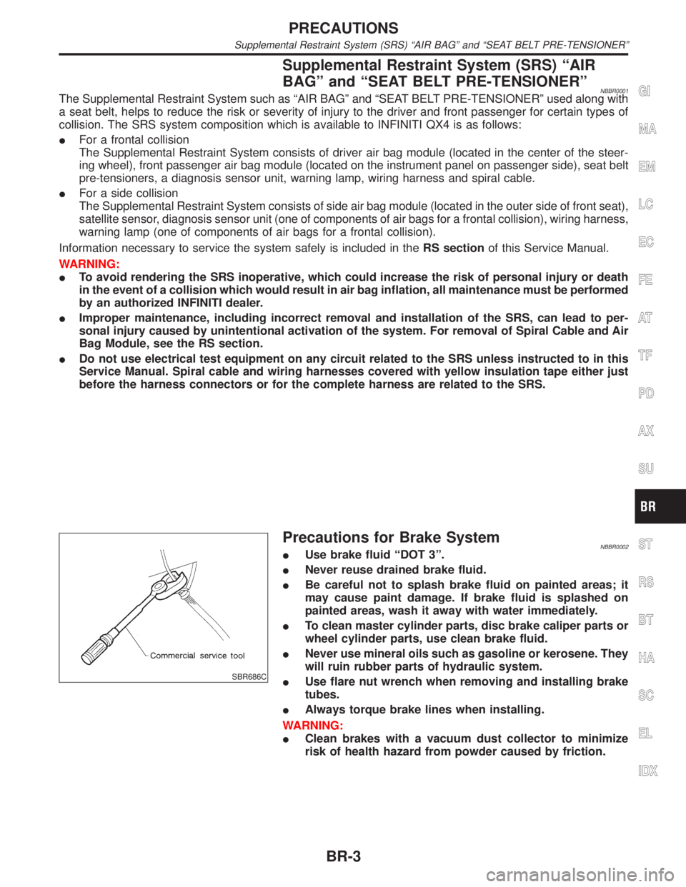
SBR686C
Precautions for Brake SystemNBBR0002IUse brake fluid ªDOT 3º.
INever reuse drained brake fluid.
IBe careful not to splash brake fluid on painted areas; it
may cause paint damage. If brake fluid is splashed on
painted areas, wash it away with water immediately.
ITo clean master cylinder parts, disc brake caliper parts or
wheel cylinder parts, use clean brake fluid.
INever use mineral oils such as gasoline or kerosene. They
will ruin rubber parts of hydraulic system.
IUse flare nut wrench when removing and installing brake
tubes.
IAlways torque brake lines when installing.
WARNING:
IClean brakes with a vacuum dust collector to minimize
risk of health hazard from powder caused by friction.
GI
MA
EM
LC
EC
FE
AT
TF
PD
AX
SU
ST
RS
BT
HA
SC
EL
IDX
PRECAUTIONS
Supplemental Restraint System (SRS) ªAIR BAGº and ªSEAT BELT PRE-TENSIONERº
BR-3
Page 394 of 2395
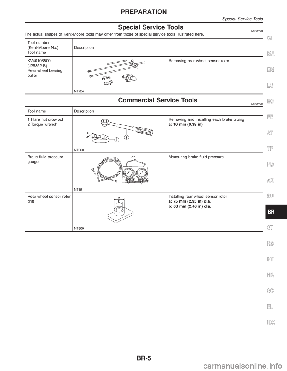
Special Service ToolsNBBR0004The actual shapes of Kent-Moore tools may differ from those of special service tools illustrated here.
Tool number
(Kent-Moore No.)
Tool nameDescription
KV40106500
(J25852-B)
Rear wheel bearing
puller
NT724
Removing rear wheel sensor rotor
Commercial Service ToolsNBBR0005
Tool name Description
1 Flare nut crowfoot
2 Torque wrench
NT360
Removing and installing each brake piping
a: 10 mm (0.39 in)
Brake fluid pressure
gauge
NT151
Measuring brake fluid pressure
Rear wheel sensor rotor
drift
NT509
Installing rear wheel sensor rotor
a: 75 mm (2.95 in) dia.
b: 63 mm (2.48 in) dia.
GI
MA
EM
LC
EC
FE
AT
TF
PD
AX
SU
ST
RS
BT
HA
SC
EL
IDX
PREPARATION
Special Service Tools
BR-5
Page 401 of 2395
InspectionNBBR0014CAUTION:
ICarefully monitor brake fluid level at master cylinder.
IUse new brake fluid ªDOT 3º.
IBe careful not to splash brake fluid on painted areas; it
may cause paint damage. If brake fluid is splashed on
paint areas, wash it away with water immediately.
IDepress pedal slowly when raising front brake pressure.
ICheck rear brake pressure 2 seconds after front brake
pressure reaches specified value.
IDisconnect harness connectors from ABS actuator and
electric unit before checking.
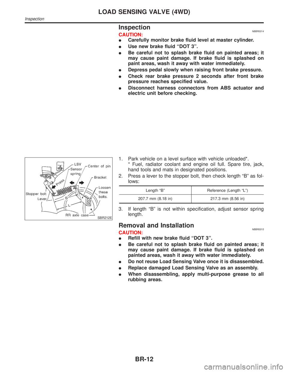
SBR212E
1. Park vehicle on a level surface with vehicle unloaded*.
* Fuel, radiator coolant and engine oil full. Spare tire, jack,
hand tools and mats in designated positions.
2. Press a lever to the stopper bolt, then check length ªBº as fol-
lows:
Length ªBº Reference (Length ªLº)
207.7 mm (8.18 in) 217.3 mm (8.56 in)
3. If length ªBº is not within specification, adjust sensor spring
length.
Removal and InstallationNBBR0015CAUTION:
IRefill with new brake fluid ªDOT 3º.
IBe careful not to splash brake fluid on painted areas; it
may cause paint damage. If brake fluid is splashed on
painted areas, wash it away with water immediately.
IDo not reuse Load Sensing Valve once it is disassembled.
IReplace damaged Load Sensing Valve as an assembly.
IWhen disassembling, apply multi-purpose grease to all
rubbing areas.
LOAD SENSING VALVE (4WD)
Inspection
BR-12
Page 422 of 2395

System ComponentsNBBR0090
SBR447EB
SBR124B
System DescriptionNBBR0091SENSORNBBR0091S01The sensor unit consists of a gear-shaped sensor rotor and a sen-
sor element. The element contains a bar magnet around which a
coil is wound. The front sensors are installed on the front spindles
and the rear sensors are installed on the rear spindles. As the
wheel rotates, the sensor generates a sine-wave pattern. The fre-
quency and voltage increase(s) as the rotating speed increases.
SBR668E
CONTROL UNIT (BUILT-IN ABS ACTUATOR AND
ELECTRIC UNIT)
NBBR0091S02The control unit computes the wheel rotating speed by the signal
current sent from the sensor. Then it supplies a DC current to the
actuator solenoid valve. It also controls ON-OFF operation of the
valve relay and motor relay. If any electrical malfunction should be
detected in the system, the control unit causes the warning lamp
to light up. In this condition, the ABS will be deactivated by the
control unit, and the vehicle's brake system reverts to normal
operation. (For control unit layout, refer to ABS ACTUATOR AND
ELECTRIC UNIT, BR-33.)
SBR482E
ABS ACTUATOR AND ELECTRIC UNITNBBR0091S03The ABS actuator and electric unit contains:
IAn electric motor and pump
ITwo relays
ISix solenoid valves, each inlet and outlet for
Ð LH front
Ð RH front
Ð Rear
IABS control unit
GI
MA
EM
LC
EC
FE
AT
TF
PD
AX
SU
ST
RS
BT
HA
SC
EL
IDX
DESCRIPTIONABS
System Components
BR-33
Page 423 of 2395
This component controls the hydraulic circuit and increases, holds
or decreases hydraulic pressure to all or individual wheels. The
ABS actuator and electric unit is serviced as an assembly.
ABS Actuator OperationNBBR0091S0301
Inlet solenoid
valveOutlet solenoid
valve
Normal brake operation OFF (Open) OFF (Closed)Master cylinder brake fluid pressure is directly
transmitted to caliper via the inlet solenoid valve.
ABS operationPressure hold ON (Closed) OFF (Closed)Hydraulic circuit is shut off to hold the caliper
brake fluid pressure.
Pressure
decreaseON (Closed) ON (Open)Caliper brake fluid is sent to reservoir via the out-
let solenoid valve. Then it is pushed up to the
master cylinder by pump.
Pressure increase OFF (Open) OFF (Closed)Master cylinder brake fluid pressure is transmitted
to caliper.
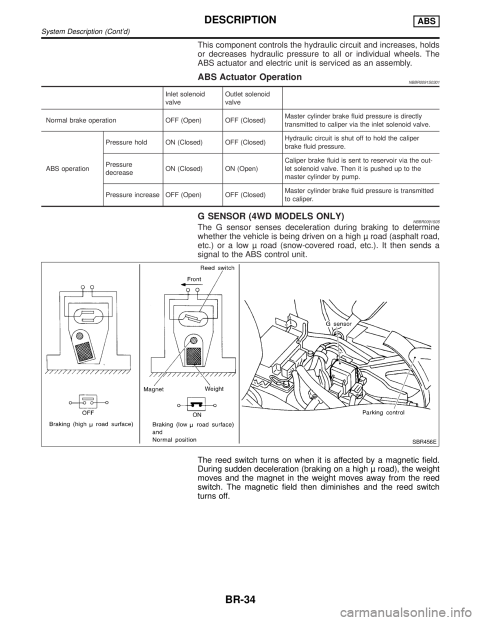
G SENSOR (4WD MODELS ONLY)NBBR0091S05The G sensor senses deceleration during braking to determine
whether the vehicle is being driven on a high road (asphalt road,
etc.) or a low road (snow-covered road, etc.). It then sends a
signal to the ABS control unit.
SBR456E
The reed switch turns on when it is affected by a magnetic field.
During sudden deceleration (braking on a high road), the weight
moves and the magnet in the weight moves away from the reed
switch. The magnetic field then diminishes and the reed switch
turns off.
DESCRIPTIONABS
System Description (Cont'd)
BR-34
Page 437 of 2395

DATA MONITOR MODENBBR0097S05
MONITOR ITEM CONDITION SPECIFICATION
FR RH SENSOR
FR LH SENSOR
RR RH SENSOR
RR LH SENSORDrive vehicle.
(Each wheel is rotating.)Wheel speed signal
(Almost the same speed as speedometer.)
STOP LAMP SW Brake is depressed.Depress the pedal: ON
Release the pedal: OFF
G-SWITCHHVehicle is driven.
Vehicle is stopped.
Brake is applied.During sudden braking while driving on high roads (asphalt
roads, etc.): OFF
While vehicle is stopped or during constant-speed driving: ON
FR RH IN SOL
FR RH OUT SOL
FR LH IN SOL
FR LH OUT SOL
RR IN SOL
RR OUT SOL1. Drive vehicle at speeds
over 30 km/h (19 MPH) for at
least 1 minute.
2. Engine is running.Operating conditions for each solenoid valve are indicated. ABS
is not operating: OFF
MOTOR RELAYABS is not operating: OFF
ABS is operating: ON
ACTUATOR RELAY
Ignition switch is ON or
engine is running.Ignition switch ON (Engine stops): OFF
Engine running: ON
WARNING LAMPABS warning lamp is turned on: ON
ABS warning lamp is turned off: OFF
BATTERY VOLT Power supply voltage for control unit
ABS OPER SIGABS is not operating: OFF
ABS is operating: ON
H: 4WD model only
ACTIVE TEST MODENBBR0097S06
TEST ITEM CONDITION JUDGEMENT
FR RH SOLENOID
FR LH SOLENOID
RR SOLENOID
Engine is running.Brake fluid pressure control operation
IN SOL OUT SOL
UP (Increase): OFF OFF
KEEP (Hold): ON OFF
DOWN (Decrease): ON ON
ABS MOTORABS actuator motor
ON: Motor runs (ABS motor relay ON)
OFF: Motor stops (ABS motor relay OFF)
ABS OPER SIGIgnition switch is ON or
engine is running.ON: Set ABS OPER SIG ªONº (ABS is operating.)
OFF: Set ABS OPER SIG ªOFFº (ABS is not operating.)
G SWITCHHIgnition switch is ON.G SWITCH (G SENSOR)
ON: Set G SWITCH MONITOR ªONº (G switch circuit is
closed.)
OFF: Set G SWITCH MONITOR ªOFFº (G switch circuit is
open.)
H: 4WD models only
NOTE:
Active test will automatically stop ten seconds after the test starts. (TEST IS STOPPED monitor shows ON.)
ON BOARD DIAGNOSTIC SYSTEM DESCRIPTIONABS
CONSULT-II Inspection Procedure (Cont'd)
BR-48
Page 438 of 2395

SEF233G
SEF234G
How to Perform Trouble Diagnoses for Quick
and Accurate Repair
NBBR0098INTRODUCTIONNBBR0098S01The ABS system has an electronic control unit to control major
functions. The control unit accepts input signals from sensors and
instantly drives the actuators. It is essential that both kinds of sig-
nals are proper and stable. It is also important to check for conven-
tional problems: such as air leaks in booster lines, lack of brake
fluid, or other problems with the brake system.
It is much more difficult to diagnose a problem that occurs intermit-
tently rather than continuously. Most intermittent problems are
caused by poor electric connections or faulty wiring. In this case,
careful checking of suspicious circuits may help prevent the
replacement of good parts.
A visual check only may not find the cause of the problems, so a
road test should be performed.
Before undertaking actual checks, take a few minutes to talk with
a customer who approaches with an ABS complaint. The customer
is a very good source of information on such problems; especially
intermittent ones. By talking to the customer, find out what symp-
toms are present and under what conditions they occur. Start your
diagnosis by looking for ªconventionalº problems first. This is one
of the best ways to troubleshoot brake problems on an ABS con-
trolled vehicle.
Also check related Service bulletins for information.
GI
MA
EM
LC
EC
FE
AT
TF
PD
AX
SU
ST
RS
BT
HA
SC
EL
IDX
TROUBLE DIAGNOSIS Ð INTRODUCTIONABS
How to Perform Trouble Diagnoses for Quick and Accurate Repair
BR-49
Page 458 of 2395

1. ABS Works FrequentlyNBBR0107
1 CHECK BRAKE FLUID PRESSURE
Check brake fluid pressure distribution.
Refer to ªInspectionº, ªLOAD SENSING VALVEº, BR-12.
Is brake fluid pressure distribution normal?
Ye s©GO TO 2.
No©Repair. Then perform Preliminary Check.
Refer to BR-50.
2 CHECK WHEEL SENSOR
1. Check wheel sensor connector for terminal damage or loose connections.
2. Perform wheel sensor mechanical check.
Refer to ª7. CHECK SENSOR ROTORº in ªDIAGNOSTIC PROCEDUREº, ªWheel Sensor or Rotorº, BR-56.
Is wheel sensor mechanism OK?
Ye s©GO TO 3.
No©Repair.
3 CHECK FRONT AXLE
Check front axles for excessive looseness. Refer to AX-4, ªFront Wheel Bearingº.
Is front axle installed properly?
Ye s©Go to ª3. CHECK WARNING LAMP INDICATIONº in ª2. Unexpected Pedal Actionº,
BR-70.
No©Repair.
2. Unexpected Pedal ActionNBBR0108
1 CHECK BRAKE PEDAL STROKE
Check brake pedal stroke.
SBR540A
Is brake pedal stroke excessively large?
Ye s©Perform Preliminary Check. Refer to BR-50.
No©GO TO 2.
GI
MA
EM
LC
EC
FE
AT
TF
PD
AX
SU
ST
RS
BT
HA
SC
EL
IDX
TROUBLE DIAGNOSES FOR SYMPTOMSABS
1. ABS Works Frequently
BR-69
Page 459 of 2395

2 CHECK MECHANICAL BRAKE SYSTEM PERFORMANCE
Disconnect ABS actuator and electric unit connector and check whether brake is effective.
Does brake system function properly when brake pedal is depressed?
Ye s©GO TO 3.
No©Perform Preliminary Check. Refer to BR-50.
3 CHECK WARNING LAMP INDICATION
Ensure warning lamp remains off while driving.
SBR672E
Is warning lamp turned off?
Ye s©GO TO 4.
No©Carry out self-diagnosis. Refer to BR-41, BR-44.
4 CHECK WHEEL SENSOR
1. Check wheel sensor connector for terminal damage or loose connection.
2. Perform wheel sensor mechanical check. Refer to ª7. CHECK SENSOR ROTORº in ªDIAGNOSTIC PROCEDUREº,
ªWheel Sensor or Rotorº, BR-56.
Is wheel sensor mechanism OK?
Ye s©Check ABS actuator and electric unit pin terminals for damage or the connection of ABS
actuator and electric unit harness connector.
Reconnect ABS actuator and electric unit harness connector.
Then retest.
No©Repair.
3. Long Stopping DistanceNBBR0109
1 CHECK MECHANICAL BRAKE SYSTEM PERFORMANCE
Disconnect ABS actuator and electric unit connector and check whether stopping distance is still long.
Does brake system function properly when brake pedal is depressed?
Ye s©Perform Preliminary Check and air bleeding (if necessary).
No©Go to ª3. CHECK WARNING LAMP INDICATIONº in ª2. Unexpected Pedal Actionº,
BR-70.
TROUBLE DIAGNOSES FOR SYMPTOMSABS
2. Unexpected Pedal Action (Cont'd)
BR-70