height adjustment INFINITI QX4 2001 Factory Owner's Manual
[x] Cancel search | Manufacturer: INFINITI, Model Year: 2001, Model line: QX4, Model: INFINITI QX4 2001Pages: 2395, PDF Size: 43.2 MB
Page 2078 of 2395
SPD364A
9. Tighten differential case couple bolts.
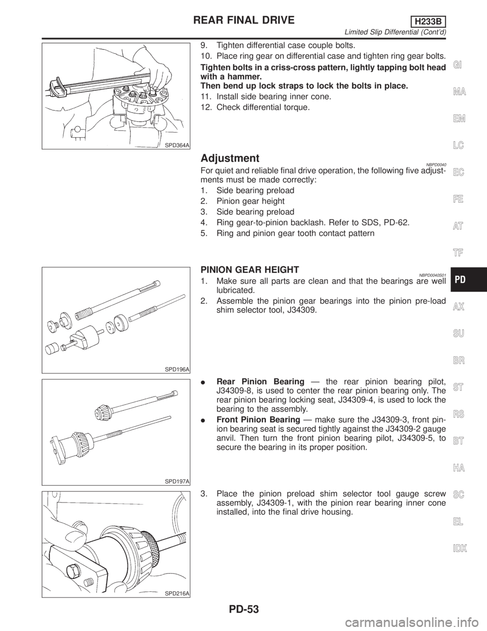
10. Place ring gear on differential case and tighten ring gear bolts.
Tighten bolts in a criss-cross pattern, lightly tapping bolt head
with a hammer.
Then bend up lock straps to lock the bolts in place.
11. Install side bearing inner cone.
12. Check differential torque.
AdjustmentNBPD0040For quiet and reliable final drive operation, the following five adjust-
ments must be made correctly:
1. Side bearing preload
2. Pinion gear height
3. Side bearing preload
4. Ring gear-to-pinion backlash. Refer to SDS, PD-62.
5. Ring and pinion gear tooth contact pattern
SPD196A
PINION GEAR HEIGHTNBPD0040S011. Make sure all parts are clean and that the bearings are well
lubricated.
2. Assemble the pinion gear bearings into the pinion pre-load
shim selector tool, J34309.
SPD197A
IRear Pinion BearingÐ the rear pinion bearing pilot,
J34309-8, is used to center the rear pinion bearing only. The
rear pinion bearing locking seat, J34309-4, is used to lock the
bearing to the assembly.
IFront Pinion BearingÐ make sure the J34309-3, front pin-
ion bearing seat is secured tightly against the J34309-2 gauge
anvil. Then turn the front pinion bearing pilot, J34309-5, to
secure the bearing in its proper position.
SPD216A
3. Place the pinion preload shim selector tool gauge screw
assembly, J34309-1, with the pinion rear bearing inner cone
installed, into the final drive housing.
GI
MA
EM
LC
EC
FE
AT
TF
AX
SU
BR
ST
RS
BT
HA
SC
EL
IDX
REAR FINAL DRIVEH233B
Limited Slip Differential (Cont'd)
PD-53
Page 2079 of 2395
SPD217A
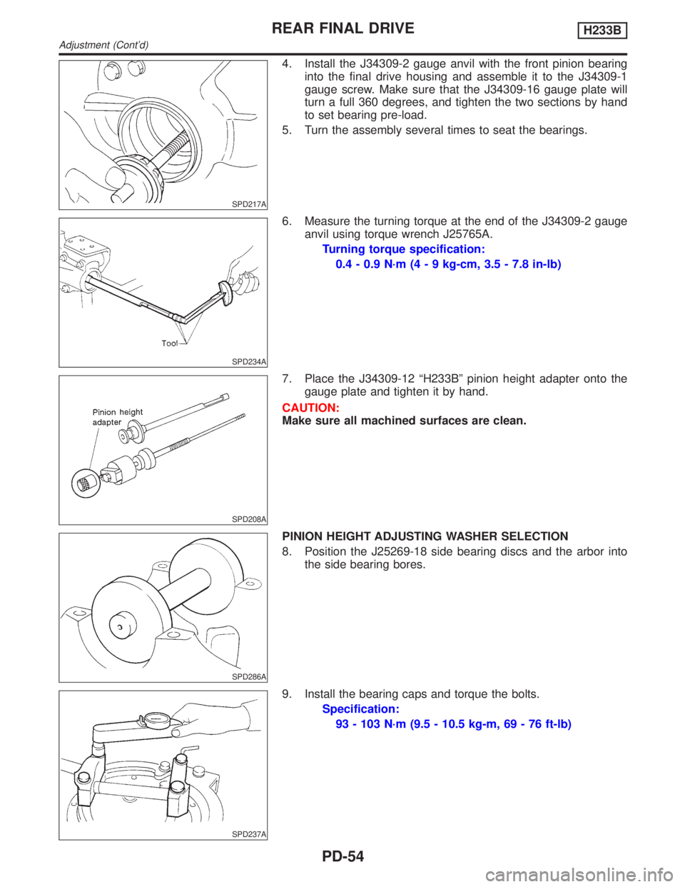
4. Install the J34309-2 gauge anvil with the front pinion bearing
into the final drive housing and assemble it to the J34309-1
gauge screw. Make sure that the J34309-16 gauge plate will
turn a full 360 degrees, and tighten the two sections by hand
to set bearing pre-load.
5. Turn the assembly several times to seat the bearings.
SPD234A
6. Measure the turning torque at the end of the J34309-2 gauge
anvil using torque wrench J25765A.
Turning torque specification:
0.4 - 0.9 N´m (4 - 9 kg-cm, 3.5 - 7.8 in-lb)
SPD208A
7. Place the J34309-12 ªH233Bº pinion height adapter onto the
gauge plate and tighten it by hand.
CAUTION:
Make sure all machined surfaces are clean.
SPD286A
PINION HEIGHT ADJUSTING WASHER SELECTION
8. Position the J25269-18 side bearing discs and the arbor into
the side bearing bores.
SPD237A
9. Install the bearing caps and torque the bolts.
Specification:
93 - 103 N´m (9.5 - 10.5 kg-m, 69 - 76 ft-lb)
REAR FINAL DRIVEH233B
Adjustment (Cont'd)
PD-54
Page 2080 of 2395
SPD204A
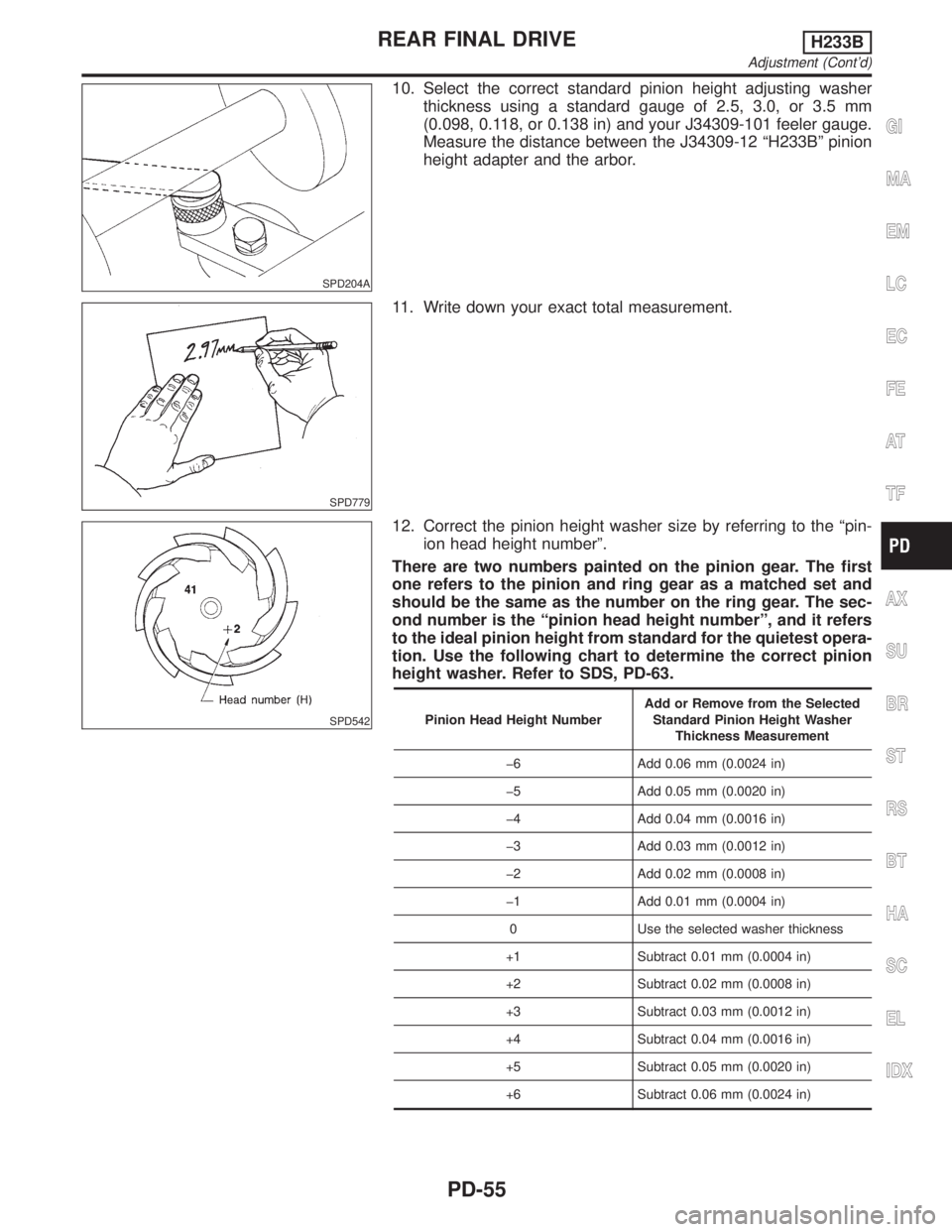
10. Select the correct standard pinion height adjusting washer
thickness using a standard gauge of 2.5, 3.0, or 3.5 mm
(0.098, 0.118, or 0.138 in) and your J34309-101 feeler gauge.
Measure the distance between the J34309-12 ªH233Bº pinion
height adapter and the arbor.
SPD779
11. Write down your exact total measurement.
SPD542
12. Correct the pinion height washer size by referring to the ªpin-
ion head height numberº.
There are two numbers painted on the pinion gear. The first
one refers to the pinion and ring gear as a matched set and
should be the same as the number on the ring gear. The sec-
ond number is the ªpinion head height numberº, and it refers
to the ideal pinion height from standard for the quietest opera-
tion. Use the following chart to determine the correct pinion
height washer. Refer to SDS, PD-63.
Pinion Head Height NumberAdd or Remove from the Selected
Standard Pinion Height Washer
Thickness Measurement
þ6 Add 0.06 mm (0.0024 in)
þ5 Add 0.05 mm (0.0020 in)
þ4 Add 0.04 mm (0.0016 in)
þ3 Add 0.03 mm (0.0012 in)
þ2 Add 0.02 mm (0.0008 in)
þ1 Add 0.01 mm (0.0004 in)
0 Use the selected washer thickness
+1 Subtract 0.01 mm (0.0004 in)
+2 Subtract 0.02 mm (0.0008 in)
+3 Subtract 0.03 mm (0.0012 in)
+4 Subtract 0.04 mm (0.0016 in)
+5 Subtract 0.05 mm (0.0020 in)
+6 Subtract 0.06 mm (0.0024 in)
GI
MA
EM
LC
EC
FE
AT
TF
AX
SU
BR
ST
RS
BT
HA
SC
EL
IDX
REAR FINAL DRIVEH233B
Adjustment (Cont'd)
PD-55
Page 2083 of 2395
SPD322
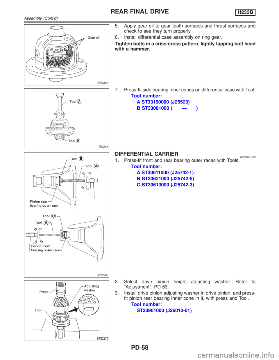
5. Apply gear oil to gear tooth surfaces and thrust surfaces and
check to see they turn properly.
6. Install differential case assembly on ring gear.
Tighten bolts in a criss-cross pattern, lightly tapping bolt head
with a hammer.
PD244
7. Press-fit side bearing inner cones on differential case with Tool.
Tool number:
A ST33190000 (J25523)
B ST33081000 ( Ð )
SPD580
DIFFERENTIAL CARRIERNBPD0041S021. Press-fit front and rear bearing outer races with Tools.
Tool number:
A ST30611000 (J25742-1)
B ST30621000 (J25742-5)
C ST30613000 (J25742-3)
SPD377
2. Select drive pinion height adjusting washer. Refer to
ªAdjustmentº, PD-53.
3. Install drive pinion adjusting washer in drive pinion, and press-
fit pinion rear bearing inner cone in it, with press and Tool.
Tool number:
ST30901000 (J26010-01)
REAR FINAL DRIVEH233B
Assembly (Cont'd)
PD-58
Page 2088 of 2395
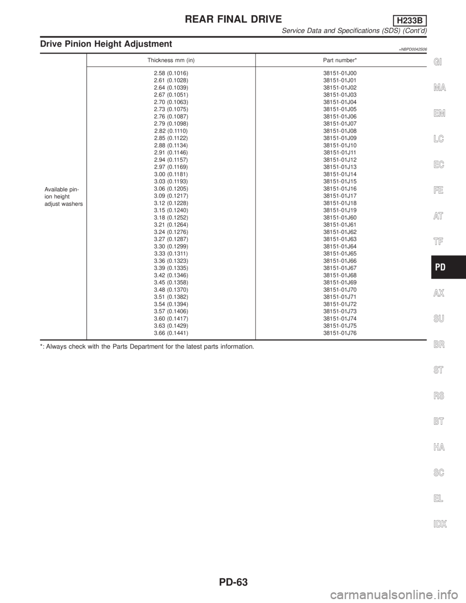
Drive Pinion Height Adjustment=NBPD0042S06
Available pin-
ion height
adjust washersThickness mm (in) Part number*
2.58 (0.1016)
2.61 (0.1028)
2.64 (0.1039)
2.67 (0.1051)
2.70 (0.1063)
2.73 (0.1075)
2.76 (0.1087)
2.79 (0.1098)
2.82 (0.1110)
2.85 (0.1122)
2.88 (0.1134)
2.91 (0.1146)
2.94 (0.1157)
2.97 (0.1169)
3.00 (0.1181)
3.03 (0.1193)
3.06 (0.1205)
3.09 (0.1217)
3.12 (0.1228)
3.15 (0.1240)
3.18 (0.1252)
3.21 (0.1264)
3.24 (0.1276)
3.27 (0.1287)
3.30 (0.1299)
3.33 (0.1311)
3.36 (0.1323)
3.39 (0.1335)
3.42 (0.1346)
3.45 (0.1358)
3.48 (0.1370)
3.51 (0.1382)
3.54 (0.1394)
3.57 (0.1406)
3.60 (0.1417)
3.63 (0.1429)
3.66 (0.1441)38151-01J00
38151-01J01
38151-01J02
38151-01J03
38151-01J04
38151-01J05
38151-01J06
38151-01J07
38151-01J08
38151-01J09
38151-01J10
38151-01J11
38151-01J12
38151-01J13
38151-01J14
38151-01J15
38151-01J16
38151-01J17
38151-01J18
38151-01J19
38151-01J60
38151-01J61
38151-01J62
38151-01J63
38151-01J64
38151-01J65
38151-01J66
38151-01J67
38151-01J68
38151-01J69
38151-01J70
38151-01J71
38151-01J72
38151-01J73
38151-01J74
38151-01J75
38151-01J76
*: Always check with the Parts Department for the latest parts information.
GI
MA
EM
LC
EC
FE
AT
TF
AX
SU
BR
ST
RS
BT
HA
SC
EL
IDX
REAR FINAL DRIVEH233B
Service Data and Specifications (SDS) (Cont'd)
PD-63