display INFINITI QX4 2001 Factory Owner's Guide
[x] Cancel search | Manufacturer: INFINITI, Model Year: 2001, Model line: QX4, Model: INFINITI QX4 2001Pages: 2395, PDF Size: 43.2 MB
Page 569 of 2395

Vacuum Cut Valve and Vacuum Cut Valve Bypass ValveNBEC0019S04Refer to EC-591.
Evaporative Emission (EVAP) Canister Purge Volume
Control Solenoid Valve
NBEC0019S05Refer to EC-367.
Fuel Tank Temperature SensorNBEC0019S06Refer to EC-309.
SEF462UA
Evap Service PortNBEC0019S07Positive pressure is delivered to the EVAP system through the
EVAP service port. If fuel vapor leakage in the EVAP system
occurs, use a leak detector to locate the leak.
SEF200U
PEF838U
PEF917U
How to Detect Fuel Vapor LeakageNBEC0019S08CAUTION:
INever use compressed air or a high pressure pump.
IDo not exceed 4.12 kPa (0.042 kg/cm
2, 0.6 psi) of pressure
in EVAP system.
NOTE:
IDo not start engine.
IImproper installation of EVAP service port adapter to the EVAP
service port may cause a leak.
With CONSULT-IINBEC0019S08011) Attach the EVAP service port adapter securely to the EVAP
service port.
2) Also attach the pressure pump and hose to the EVAP service
port adapter.
3) Turn ignition switch ªONº.
4) Select the ªEVAP SYSTEM CLOSEº of ªWORK SUPPORT
MODEº with CONSULT-II.
5) Touch ªSTARTº. A bar graph (Pressure indicating display) will
appear on the screen.
6) Apply positive pressure to the EVAP system until the pressure
indicator reaches the middle of the bar graph.
7) Remove EVAP service port adapter and hose with pressure
pump.
8) Locate the leak using a leak detector. Refer to ªEVAPORATIVE
EMISSION LINE DRAWINGº, EC-36.
ENGINE AND EMISSION BASIC CONTROL SYSTEM DESCRIPTION
Evaporative Emission System (Cont'd)
EC-34
Page 581 of 2395

INSPECTION PROCEDURE=NBEC0028S02
1 INSPECTION START
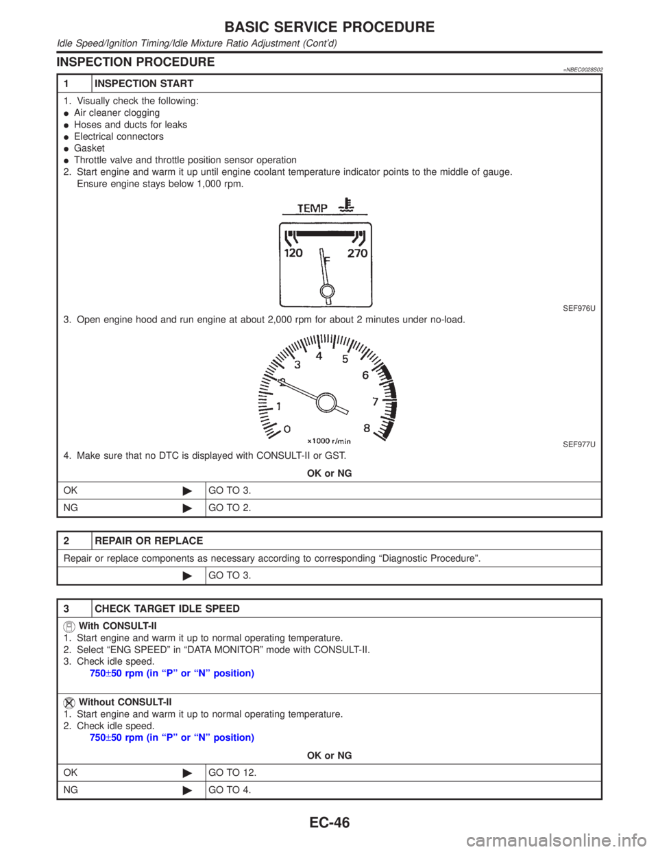
1. Visually check the following:
IAir cleaner clogging
IHoses and ducts for leaks
IElectrical connectors
IGasket
IThrottle valve and throttle position sensor operation
2. Start engine and warm it up until engine coolant temperature indicator points to the middle of gauge.
Ensure engine stays below 1,000 rpm.
SEF976U
3. Open engine hood and run engine at about 2,000 rpm for about 2 minutes under no-load.
SEF977U
4. Make sure that no DTC is displayed with CONSULT-II or GST.
OK or NG
OK©GO TO 3.
NG©GO TO 2.
2 REPAIR OR REPLACE
Repair or replace components as necessary according to corresponding ªDiagnostic Procedureº.
©GO TO 3.
3 CHECK TARGET IDLE SPEED
With CONSULT-II
1. Start engine and warm it up to normal operating temperature.
2. Select ªENG SPEEDº in ªDATA MONITORº mode with CONSULT-II.
3. Check idle speed.
750±50 rpm (in ªPº or ªNº position)
Without CONSULT-II
1. Start engine and warm it up to normal operating temperature.
2. Check idle speed.
750±50 rpm (in ªPº or ªNº position)
OK or NG
OK©GO TO 12.
NG©GO TO 4.
BASIC SERVICE PROCEDURE
Idle Speed/Ignition Timing/Idle Mixture Ratio Adjustment (Cont'd)
EC-46
Page 585 of 2395

18 ERASE UNNECESSARY DTC
After this inspection, unnecessary DTC No. might be displayed.
Erase the stored memory in ECM and TCM (Transmission control module).
Refer to ªHOW TO ERASE EMISSION-RELATED DIAGNOSTIC INFORMATIONº, EC-72 and AT-35, ªHOW TO ERASE
DTCº.
With CONSULT-II©GO TO 19.
Without CONSULT-II©GO TO 20.
19 CHECK HEATED OXYGEN SENSOR 1 (FRONT) (BANK 2) SIGNAL
With CONSULT-II
1. Run engine at about 2,000 rpm for about 2 minutes under no-load.
2. See ªHO2S1 MNTR (B2)º in ªDATA MONITORº mode.
3. Running engine at 2,000 rpm under no-load (engine is warmed up to normal operating temperature.), check that the
monitor fluctuates between ªLEANº and ªRICHº more than 5 times during 10 seconds.
SEF945Y
OK or NG
OK©GO TO 23.
NG (Monitor does not
fluctuate.)©GO TO 28.
NG (Monitor fluctuates
less than 5 times.)©GO TO 21.
20 CHECK HEATED OXYGEN SENSOR 1 (FRONT) (BANK 2) SIGNAL
Without CONSULT-II
1. Run engine at about 2,000 rpm for about 2 minutes under no-load.
2. Set voltmeter probe between ECM terminal 62 and ground.
3. Make sure that the voltage fluctuates between 0 - 0.3V and 0.6 - 1.0V more than 5 times during 10 seconds at 2,000
rpm.
1 time: 0 - 0.3V®0.6 - 1.0V®0 - 0.3V
2 times: 0 - 0.3V®0.6 - 1.0V®0 - 0.3V®0.6 - 1.0V®0 - 0.3V
OK or NG
OK©GO TO 23.
NG (Voltage does not
fluctuate.)©GO TO 28.
NG (Voltage fluctuates
less than 5 times.)©GO TO 21.
BASIC SERVICE PROCEDURE
Idle Speed/Ignition Timing/Idle Mixture Ratio Adjustment (Cont'd)
EC-50
Page 592 of 2395

SEF452Y
Idle Air Volume LearningNBEC0642
SEF454Y
SEF455Y
DESCRIPTIONNBEC0642S01ªIdle Air Volume Learningº is an operation to learn the idle air vol-
ume that keeps each engine within the specific range. It must be
performed under any of the following conditions:
IEach time IACV-AAC valve, throttle body or ECM is replaced.
IIdle speed or ignition timing is out of specification.
PRE-CONDITIONINGNBEC0642S02Before performing ªIdle Air Volume Learningº, make sure that all of
the following conditions are satisfied.
Learning will be cancelled if any of the following conditions are
missed for even a moment.
IBattery voltage: More than 12.9V (At idle)
IEngine coolant temperature: 70 - 99ÉC (158 - 210ÉF)
IPNP switch: ON
IElectric load switch: OFF
(Air conditioner, headlamp, rear window defogger)
On vehicles equipped with daytime running light systems, if
the parking brake is applied before the engine is started the
headlamp will not illuminate.
ICooling fan motor: Not operating
ISteering wheel: Neutral (Straight-ahead position)
IVehicle speed: Stopped
ITransmission: Warmed-up
For A/T models with CONSULT-II, drive vehicle until ªFLUID
TEMP SEº in ªDATA MONITORº mode of ªA/Tº system indi-
cates less than 0.9V.
For A/T models without CONSULT-II, drive vehicle for 10 min-
utes.
OPERATION PROCEDURENBEC0642S03With CONSULT-IINBEC0642S03011. Turn ignition switch ªONº and wait at least 1 second.
2. Turn ignition switch ªOFFº and wait at least 10 seconds.
3. Start engine and warm it up to normal operating temperature.
4. Check that all items listed under the topic ªPRE-CONDITION-
INGº (previously mentioned) are in good order.
5. Turn ignition switch ªOFFº and wait at least 10 seconds.
6. Start the engine and let it idle for at least 30 seconds.
7. Select ªIDLE AIR VOL LEARNº in ªWORK SUPPORTº mode.
8. Touch ªSTARTº and wait 20 seconds.
9. Make sure that ªCMPLTº is displayed on CONSULT-II screen.
If ªINCMPº is displayed, ªIdle Air Volume Learningº will not be
carried out successfully. In this case, find the cause of the
problem by referring to the NOTE below.
10. Rev up the engine two or three times. Make sure that idle
speed and ignition timing are within specifications.
ITEM SPECIFICATION
Idle speed 750±50 rpm (in ªPº or ªNº position)
Ignition timing 15ɱ5É BTDC (in ªPº or ªNº position)
GI
MA
EM
LC
FE
AT
TF
PD
AX
SU
BR
ST
RS
BT
HA
SC
EL
IDX
BASIC SERVICE PROCEDURE
Idle Air Volume Learning
EC-57
Page 594 of 2395

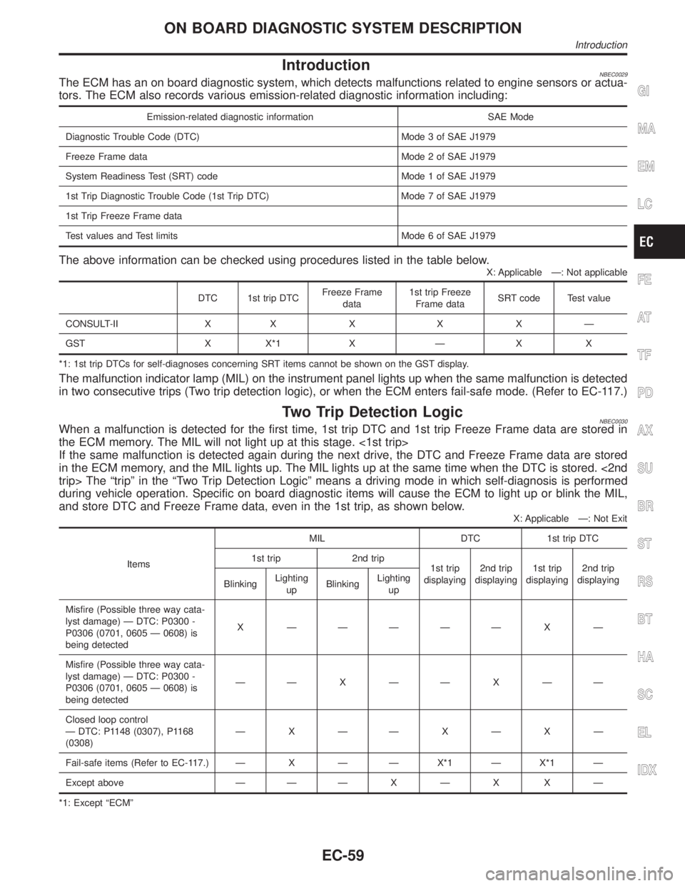
IntroductionNBEC0029The ECM has an on board diagnostic system, which detects malfunctions related to engine sensors or actua-
tors. The ECM also records various emission-related diagnostic information including:
Emission-related diagnostic information SAE Mode
Diagnostic Trouble Code (DTC) Mode 3 of SAE J1979
Freeze Frame data Mode 2 of SAE J1979
System Readiness Test (SRT) code Mode 1 of SAE J1979
1st Trip Diagnostic Trouble Code (1st Trip DTC) Mode 7 of SAE J1979
1st Trip Freeze Frame data
Test values and Test limits Mode 6 of SAE J1979
The above information can be checked using procedures listed in the table below.
X: Applicable Ð: Not applicable
DTC 1st trip DTCFreeze Frame
data1st trip Freeze
Frame dataSRT code Test value
CONSULT-II X X X X X Ð
GST X X*1 X Ð X X
*1: 1st trip DTCs for self-diagnoses concerning SRT items cannot be shown on the GST display.
The malfunction indicator lamp (MIL) on the instrument panel lights up when the same malfunction is detected
in two consecutive trips (Two trip detection logic), or when the ECM enters fail-safe mode. (Refer to EC-117.)
Two Trip Detection LogicNBEC0030When a malfunction is detected for the first time, 1st trip DTC and 1st trip Freeze Frame data are stored in
the ECM memory. The MIL will not light up at this stage. <1st trip>
If the same malfunction is detected again during the next drive, the DTC and Freeze Frame data are stored
in the ECM memory, and the MIL lights up. The MIL lights up at the same time when the DTC is stored. <2nd
trip> The ªtripº in the ªTwo Trip Detection Logicº means a driving mode in which self-diagnosis is performed
during vehicle operation. Specific on board diagnostic items will cause the ECM to light up or blink the MIL,
and store DTC and Freeze Frame data, even in the 1st trip, as shown below.
X: Applicable Ð: Not Exit
ItemsMIL DTC 1st trip DTC
1st trip 2nd trip
1st trip
displaying2nd trip
displaying1st trip
displaying2nd trip
displaying
BlinkingLighting
upBlinkingLighting
up
Misfire (Possible three way cata-
lyst damage) Ð DTC: P0300 -
P0306 (0701, 0605 Ð 0608) is
being detectedX ÐÐÐÐÐ X Ð
Misfire (Possible three way cata-
lyst damage) Ð DTC: P0300 -
P0306 (0701, 0605 Ð 0608) is
being detectedÐÐ X ÐÐ X ÐÐ
Closed loop control
Ð DTC: P1148 (0307), P1168
(0308)ÐXÐÐXÐXÐ
Fail-safe items (Refer to EC-117.) Ð X Ð Ð X*1 Ð X*1 Ð
Except above Ð Ð Ð X Ð X X Ð
*1: Except ªECMº
GI
MA
EM
LC
FE
AT
TF
PD
AX
SU
BR
ST
RS
BT
HA
SC
EL
IDX
ON BOARD DIAGNOSTIC SYSTEM DESCRIPTION
Introduction
EC-59
Page 595 of 2395

Emission-related Diagnostic InformationNBEC0031DTC AND 1ST TRIP DTCNBEC0031S01The 1st trip DTC (whose number is the same as the DTC number) is displayed for the latest self-diagnostic
result obtained. If the ECM memory was cleared previously, and the 1st trip DTC did not reoccur, the 1st trip
DTC will not be displayed.
If a malfunction is detected during the 1st trip, the 1st trip DTC is stored in the ECM memory. The MIL will not
light up (two trip detection logic). If the same malfunction is not detected in the 2nd trip (meeting the required
driving pattern), the 1st trip DTC is cleared from the ECM memory. If the same malfunction is detected in the
2nd trip, both the 1st trip DTC and DTC are stored in the ECM memory and the MIL lights up. In other words,
the DTC is stored in the ECM memory and the MIL lights up when the same malfunction occurs in two con-
secutive trips. If a 1st trip DTC is stored and a non-diagnostic operation is performed between the 1st and
2nd trips, only the 1st trip DTC will continue to be stored. For malfunctions that blink or light up the MIL dur-
ing the 1st trip, the DTC and 1st trip DTC are stored in the ECM memory.
Procedures for clearing the DTC and the 1st trip DTC from the ECM memory are described in ªHOW TO
ERASE EMISSION-RELATED DIAGNOSTIC INFORMATIONº, EC-72.
For malfunctions in which 1st trip DTCs are displayed, refer to EC-69. These items are required by legal
regulations to continuously monitor the system/component. In addition, the items monitored non-continuously
are also displayed on CONSULT-II.
1st trip DTC is specified in Mode 7 of SAE J1979. 1st trip DTC detection occurs without lighting up the MIL
and therefore does not warn the driver of a problem. However, 1st trip DTC detection will not prevent the
vehicle from being tested, for example during Inspection/Maintenance (I/M) tests.
When a 1st trip DTC is detected, check, print out or write down and erase (1st trip) DTC and Freeze Frame
data as specified in ªWork Flowº procedure Step II, refer to EC-99. Then perform ªDTC Confirmation Proce-
dureº or ªOverall Function Checkº to try to duplicate the problem. If the malfunction is duplicated, the item
requires repair.
How to Read DTC and 1st Trip DTCNBEC0031S0101DTC and 1st trip DTC can be read by the following methods.
With CONSULT-II
With GST
CONSULT-II or GST (Generic Scan Tool) Examples: P0340, P1320, P0705, P0750, etc.
These DTCs are prescribed by SAE J2012.
(CONSULT-II also displays the malfunctioning component or system.)
I1st trip DTC No. is the same as DTC No.
IOutput of a DTC indicates a malfunction. However, GST does not indicate whether the malfunction
is still occurring or has occurred in the past and has returned to normal. CONSULT-II can identify
malfunction status as shown below. Therefore, using CONSULT-II (if available) is recommended.
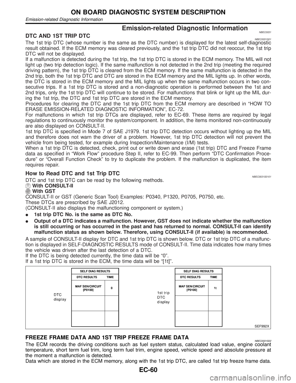
A sample of CONSULT-II display for DTC and 1st trip DTC is shown below. DTC or 1st trip DTC of a malfunc-
tion is displayed in SELF-DIAGNOSTIC RESULTS mode of CONSULT-II. Time data indicates how many times
the vehicle was driven after the last detection of a DTC.
If the DTC is being detected currently, the time data will be ª0º.
If a 1st trip DTC is stored in the ECM, the time data will be ª[1t]º.
SEF992X
FREEZE FRAME DATA AND 1ST TRIP FREEZE FRAME DATANBEC0031S02The ECM records the driving conditions such as fuel system status, calculated load value, engine coolant
temperature, short term fuel trim, long term fuel trim, engine speed, vehicle speed and absolute pressure at
the moment a malfunction is detected.
Data which are stored in the ECM memory, along with the 1st trip DTC, are called 1st trip freeze frame data.
ON BOARD DIAGNOSTIC SYSTEM DESCRIPTION
Emission-related Diagnostic Information
EC-60
Page 596 of 2395

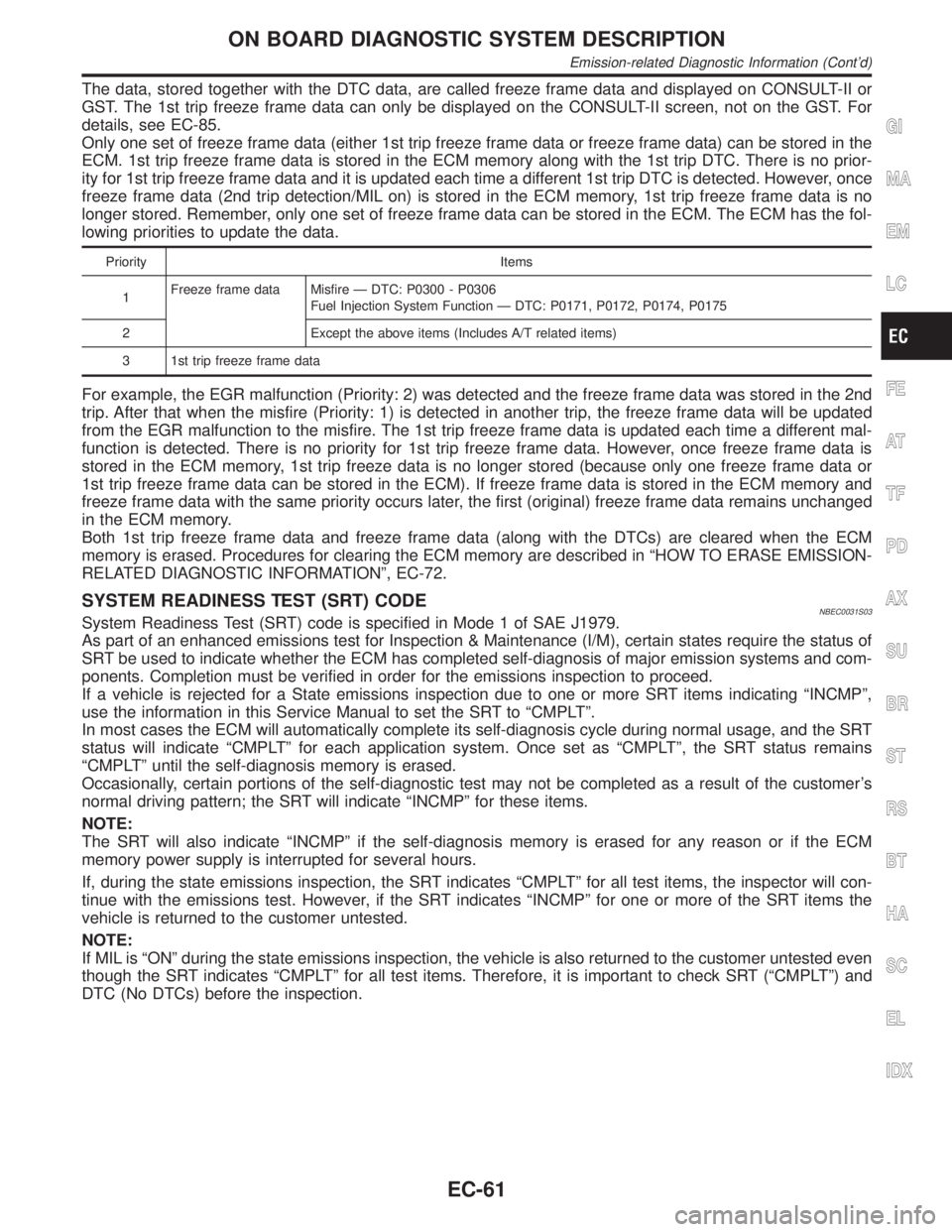
The data, stored together with the DTC data, are called freeze frame data and displayed on CONSULT-II or
GST. The 1st trip freeze frame data can only be displayed on the CONSULT-II screen, not on the GST. For
details, see EC-85.
Only one set of freeze frame data (either 1st trip freeze frame data or freeze frame data) can be stored in the
ECM. 1st trip freeze frame data is stored in the ECM memory along with the 1st trip DTC. There is no prior-
ity for 1st trip freeze frame data and it is updated each time a different 1st trip DTC is detected. However, once
freeze frame data (2nd trip detection/MIL on) is stored in the ECM memory, 1st trip freeze frame data is no
longer stored. Remember, only one set of freeze frame data can be stored in the ECM. The ECM has the fol-
lowing priorities to update the data.
Priority Items
1Freeze frame data Misfire Ð DTC: P0300 - P0306
Fuel Injection System Function Ð DTC: P0171, P0172, P0174, P0175
2 Except the above items (Includes A/T related items)
3 1st trip freeze frame data
For example, the EGR malfunction (Priority: 2) was detected and the freeze frame data was stored in the 2nd
trip. After that when the misfire (Priority: 1) is detected in another trip, the freeze frame data will be updated
from the EGR malfunction to the misfire. The 1st trip freeze frame data is updated each time a different mal-
function is detected. There is no priority for 1st trip freeze frame data. However, once freeze frame data is
stored in the ECM memory, 1st trip freeze data is no longer stored (because only one freeze frame data or
1st trip freeze frame data can be stored in the ECM). If freeze frame data is stored in the ECM memory and
freeze frame data with the same priority occurs later, the first (original) freeze frame data remains unchanged
in the ECM memory.
Both 1st trip freeze frame data and freeze frame data (along with the DTCs) are cleared when the ECM
memory is erased. Procedures for clearing the ECM memory are described in ªHOW TO ERASE EMISSION-
RELATED DIAGNOSTIC INFORMATIONº, EC-72.
SYSTEM READINESS TEST (SRT) CODENBEC0031S03System Readiness Test (SRT) code is specified in Mode 1 of SAE J1979.
As part of an enhanced emissions test for Inspection & Maintenance (I/M), certain states require the status of
SRT be used to indicate whether the ECM has completed self-diagnosis of major emission systems and com-
ponents. Completion must be verified in order for the emissions inspection to proceed.
If a vehicle is rejected for a State emissions inspection due to one or more SRT items indicating ªINCMPº,
use the information in this Service Manual to set the SRT to ªCMPLTº.
In most cases the ECM will automatically complete its self-diagnosis cycle during normal usage, and the SRT
status will indicate ªCMPLTº for each application system. Once set as ªCMPLTº, the SRT status remains
ªCMPLTº until the self-diagnosis memory is erased.
Occasionally, certain portions of the self-diagnostic test may not be completed as a result of the customer's
normal driving pattern; the SRT will indicate ªINCMPº for these items.
NOTE:
The SRT will also indicate ªINCMPº if the self-diagnosis memory is erased for any reason or if the ECM
memory power supply is interrupted for several hours.
If, during the state emissions inspection, the SRT indicates ªCMPLTº for all test items, the inspector will con-
tinue with the emissions test. However, if the SRT indicates ªINCMPº for one or more of the SRT items the
vehicle is returned to the customer untested.
NOTE:
If MIL is ªONº during the state emissions inspection, the vehicle is also returned to the customer untested even
though the SRT indicates ªCMPLTº for all test items. Therefore, it is important to check SRT (ªCMPLTº) and
DTC (No DTCs) before the inspection.
GI
MA
EM
LC
FE
AT
TF
PD
AX
SU
BR
ST
RS
BT
HA
SC
EL
IDX
ON BOARD DIAGNOSTIC SYSTEM DESCRIPTION
Emission-related Diagnostic Information (Cont'd)
EC-61
Page 599 of 2395

SEF170Z
*1 EC-60 *2 EC-64 *3 EC-65
How to Display SRT CodeNBEC0031S0301With CONSULT-II
Selecting ªSRT STATUSº in ªDTC CONFIRMATIONº mode with CONSULT-II.
For items whose SRT codes are set, a ªCMPLTº is displayed on the CONSULT-II screen; for items whose SRT
codes are not set, ªINCMPº is displayed.
With GST
Selecting Mode 1 with GST (Generic Scan Tool)
A sample of CONSULT-II display for SRT code is shown below.
ªINCMPº means the self-diagnosis is incomplete and SRT is not set. ªCMPLTº means the self-diagnosis is
complete and SRT is set.
ON BOARD DIAGNOSTIC SYSTEM DESCRIPTION
Emission-related Diagnostic Information (Cont'd)
EC-64
Page 603 of 2395
![INFINITI QX4 2001 Factory Owners Guide For normal acceleration in low altitude areas
[less than 1,219 m (4,000 ft)]:For quick acceleration in low altitude
areas and high altitude areas
[over 1,219 m (4,000 ft)]:
Gear changeACCEL shift poin INFINITI QX4 2001 Factory Owners Guide For normal acceleration in low altitude areas
[less than 1,219 m (4,000 ft)]:For quick acceleration in low altitude
areas and high altitude areas
[over 1,219 m (4,000 ft)]:
Gear changeACCEL shift poin](/img/42/57027/w960_57027-602.png)
For normal acceleration in low altitude areas
[less than 1,219 m (4,000 ft)]:For quick acceleration in low altitude
areas and high altitude areas
[over 1,219 m (4,000 ft)]:
Gear changeACCEL shift point
km/h (MPH)CRUISE shift point
km/h (MPH)km/h (MPH)
1st to 2nd 21 (13) 21 (13) 24 (15)
2nd to 3rd 37 (23) 26 (16) 40 (25)
3rd to 4th 53 (33) 44 (27) 64 (40)
4th to 5th 63 (39) 58 (36) 72 (45)
Suggested Maximum Speed in Each Gear
Downshift to a lower gear if the engine is not running smoothly, or if you need to accelerate.
Do not exceed the maximum suggested speed (shown below) in any gear. For level road driving, use the
highest gear suggested for that speed. Always observe posted speed limits and drive according to the road
conditions to ensure safe operation. Do not over-rev the engine when shifting to a lower gear as it may cause
engine damage or loss of vehicle control.
Gear km/h (MPH)
1st 50 (30)
2nd 89 (55)
3rd 128 (80)
4th Ð
5th Ð
TEST VALUE AND TEST LIMIT (GST ONLY Ð NOT APPLICABLE TO CONSULT-II)NBEC0031S04The following is the information specified in Mode 6 of SAE J1979.
The test value is a parameter used to determine whether a system/circuit diagnostic test is ªOKº or ªNGº while
being monitored by the ECM during self-diagnosis. The test limit is a reference value which is specified as the
maximum or minimum value and is compared with the test value being monitored.
Items for which these data (test value and test limit) are displayed are the same as SRT code items (30 test
items).
These data (test value and test limit) are specified by Test ID (TID) and Component ID (CID) and can be dis-
played on the GST screen.
X: Applicable Ð: Not applicable
SRT item Self-diagnostic test itemTest value (GST display)
Test limit Application
TID CID
C ATA LY S TThree way catalyst function
(Right bank)01H 01H Max. X
Three way catalyst function
(Left bank)03H 02H Max. X
EVAP SYSTEMEVAP control system
(Small leak)05H 03H Max. X
EVAP control system purge flow
monitoring06H 83H Min. X
ON BOARD DIAGNOSTIC SYSTEM DESCRIPTION
Emission-related Diagnostic Information (Cont'd)
EC-68
Page 604 of 2395

SRT item Self-diagnostic test itemTest value (GST display)
Test limit Application
TID CID
O2 SENSORHeated oxygen sensor 1 (front)
(bank 1)09H 04H Max. X
0AH 84H Min. X
0BH 04H Max. X
0CH 04H Max. X
0DH 04H Max. X
Heated oxygen sensor 1 (front)
(bank 2)11H 05H Max. X
12H 85H Min. X
13H 05H Max. X
14H 05H Max. X
15H 05H Max. X
Heated oxygen sensor 2 (rear)
(bank 1)19H 86H Min. X
1AH 86H Min. X
1BH 06H Max. X
1CH 06H Max. X
Heated oxygen sensor 2 (rear)
(bank 2)21H 87H Min. X
22H 87H Min. X
23H 07H Max. X
24H 07H Max. X
O2 SENSOR HEATERHeated oxygen sensor 1 (front) heater
(bank 1)29H 08H Max. X
2AH 88H Min. X
Heated oxygen sensor 1 (front) heater
(bank 2)2BH 09H Max. X
2CH 89H Min. X
Heated oxygen sensor 2 (rear) heater
(bank 1)2DH 0AH Max. X
2EH 8AH Min. X
Heated oxygen sensor 2 (rear) heater
(bank 2)2FH 0BH Max. X
30H 8BH Min. X
EMISSION-RELATED DIAGNOSTIC INFORMATION ITEMSNBEC0031S05X: Applicable Ð: Not applicable
Items
(CONSULT-II screen terms)DTC*1 SRT codeTest value/ Test
limit
(GST only)1st trip DTC*1 Reference page
NO DTC IS DETECTED.
FURTHER TESTING
MAY BE REQUIRED.P0000ÐÐÐÐ
MAF SEN/CIRCUIT P0100 Ð Ð X EC-150
ABSL PRES SEN/CIRC P0105 Ð Ð X EC-158
AIR TEMP SEN/CIRC P0110 Ð Ð X EC-164
COOLANT T SEN/CIRC P0115 Ð Ð X EC-169
GI
MA
EM
LC
FE
AT
TF
PD
AX
SU
BR
ST
RS
BT
HA
SC
EL
IDX
ON BOARD DIAGNOSTIC SYSTEM DESCRIPTION
Emission-related Diagnostic Information (Cont'd)
EC-69