engine coolant INFINITI QX4 2001 Factory Owner's Guide
[x] Cancel search | Manufacturer: INFINITI, Model Year: 2001, Model line: QX4, Model: INFINITI QX4 2001Pages: 2395, PDF Size: 43.2 MB
Page 626 of 2395
![INFINITI QX4 2001 Factory Owners Guide Monitored item [Unit]ECM
input
signalsMain
signalsDescription Remarks
A/F ALPHA-B1 [%]q
IIndicates the mean value of the air-fuel ratio
feedback correction factor per cycle.IWhen the engine is running INFINITI QX4 2001 Factory Owners Guide Monitored item [Unit]ECM
input
signalsMain
signalsDescription Remarks
A/F ALPHA-B1 [%]q
IIndicates the mean value of the air-fuel ratio
feedback correction factor per cycle.IWhen the engine is running](/img/42/57027/w960_57027-625.png)
Monitored item [Unit]ECM
input
signalsMain
signalsDescription Remarks
A/F ALPHA-B1 [%]q
IIndicates the mean value of the air-fuel ratio
feedback correction factor per cycle.IWhen the engine is running, specifi-
cation range is indicated.
IThis data also includes the data for
the air-fuel ratio learning control. A/F ALPHA-B2 [%]q
NOTE:
IAny monitored item that does not match the vehicle being diagnosed is deleted from the display automatically.
IRegarding R50 model, ªB1º indicates bank 1 and ªB2º indicates bank 2.
ACTIVE TEST MODENBEC0034S07
TEST ITEM CONDITION JUDGEMENT CHECK ITEM (REMEDY)
FUEL INJECTIONIEngine: Return to the original
trouble condition
IChange the amount of fuel injec-
tion using CONSULT-II.If trouble symptom disappears, see
CHECK ITEM.IHarness and connector
IFuel injectors
IHeated oxygen sensor
IGNITION TIMINGIEngine: Return to the original
trouble condition
ITiming light: Set
IRetard the ignition timing using
CONSULT-II.If trouble symptom disappears, see
CHECK ITEM.IAdjust initial ignition timing
IACV-AAC/V
OPENINGIEngine: After warming up, idle
the engine.
IChange the IACV-AAC valve
opening percent using CON-
SULT-II.Engine speed changes according
to the opening percent.IHarness and connector
IIACV-AAC valve
POWER BAL-
ANCEIEngine: After warming up, idle
the engine.
IA/C switch ªOFFº
IShift lever ªNº
ICut off each injector signal one
at a time using CONSULT-II.Engine runs rough or dies.IHarness and connector
ICompression
IInjectors
IPower transistor
ISpark plugs
IIgnition coils
ENG COOLANT
TEMPIEngine: Return to the original
trouble condition
IChange the engine coolant tem-
perature using CONSULT-II.If trouble symptom disappears, see
CHECK ITEM.IHarness and connector
IEngine coolant temperature sen-
sor
IFuel injectors
FUEL PUMP
RELAYIIgnition switch: ON
(Engine stopped)
ITurn the fuel pump relay ªONº
and ªOFFº using CONSULT-II
and listen to operating sound.Fuel pump relay makes the operat-
ing sound.IHarness and connector
IFuel pump relay
VIAS SOL VALVEIIgnition switch: ON
ITurn solenoid valve ªONº and
ªOFFº with CONSULT-II and lis-
ten for operating sound.Solenoid valve makes an operating
sound.IHarness and connector
ISolenoid valve
SWIRL CONT
S O L VA LV EIIgnition switch: ON
ITurn solenoid valve ªONº and
ªOFFº with CONSULT-II and lis-
ten for operating sound.Solenoid valve makes an operating
sound.IHarness and connector
ISolenoid valve
PURG VOL
CONT/VIEngine: After warming up, run
engine at 1,500 rpm.
IChange the EVAP canister purge
volume control solenoid valve
opening percent using CON-
SULT-II.Engine speed changes according
to the opening percent.IHarness and connector
ISolenoid valve
GI
MA
EM
LC
FE
AT
TF
PD
AX
SU
BR
ST
RS
BT
HA
SC
EL
IDX
ON BOARD DIAGNOSTIC SYSTEM DESCRIPTION
CONSULT-II (Cont'd)
EC-91
Page 651 of 2395
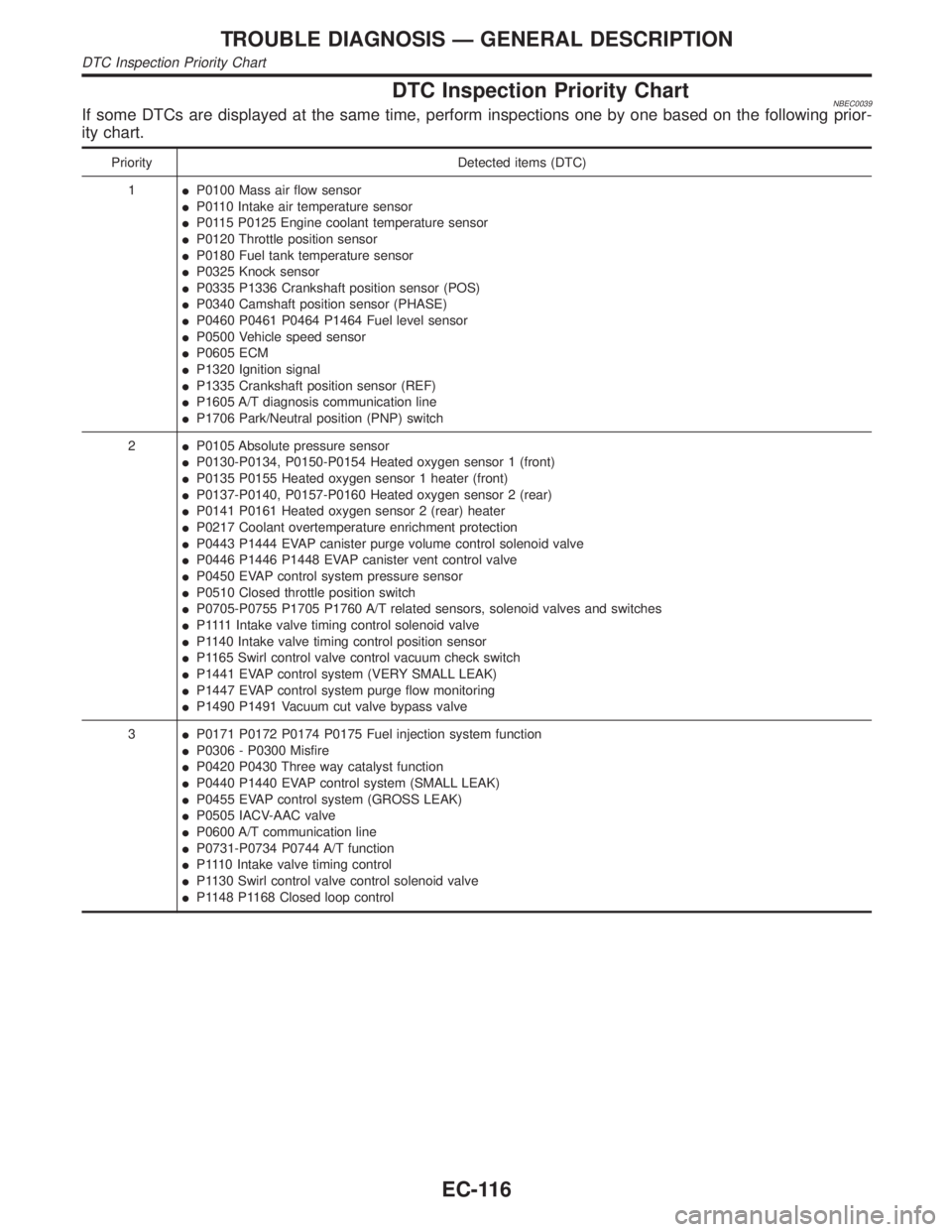
DTC Inspection Priority ChartNBEC0039If some DTCs are displayed at the same time, perform inspections one by one based on the following prior-
ity chart.
Priority Detected items (DTC)
1IP0100 Mass air flow sensor
IP0110 Intake air temperature sensor
IP0115 P0125 Engine coolant temperature sensor
IP0120 Throttle position sensor
IP0180 Fuel tank temperature sensor
IP0325 Knock sensor
IP0335 P1336 Crankshaft position sensor (POS)
IP0340 Camshaft position sensor (PHASE)
IP0460 P0461 P0464 P1464 Fuel level sensor
IP0500 Vehicle speed sensor
IP0605 ECM
IP1320 Ignition signal
IP1335 Crankshaft position sensor (REF)
IP1605 A/T diagnosis communication line
IP1706 Park/Neutral position (PNP) switch
2IP0105 Absolute pressure sensor
IP0130-P0134, P0150-P0154 Heated oxygen sensor 1 (front)
IP0135 P0155 Heated oxygen sensor 1 heater (front)
IP0137-P0140, P0157-P0160 Heated oxygen sensor 2 (rear)
IP0141 P0161 Heated oxygen sensor 2 (rear) heater
IP0217 Coolant overtemperature enrichment protection
IP0443 P1444 EVAP canister purge volume control solenoid valve
IP0446 P1446 P1448 EVAP canister vent control valve
IP0450 EVAP control system pressure sensor
IP0510 Closed throttle position switch
IP0705-P0755 P1705 P1760 A/T related sensors, solenoid valves and switches
IP 1111Intake valve timing control solenoid valve
IP1140 Intake valve timing control position sensor
IP1165 Swirl control valve control vacuum check switch
IP1441 EVAP control system (VERY SMALL LEAK)
IP1447 EVAP control system purge flow monitoring
IP1490 P1491 Vacuum cut valve bypass valve
3IP0171 P0172 P0174 P0175 Fuel injection system function
IP0306 - P0300 Misfire
IP0420 P0430 Three way catalyst function
IP0440 P1440 EVAP control system (SMALL LEAK)
IP0455 EVAP control system (GROSS LEAK)
IP0505 IACV-AAC valve
IP0600 A/T communication line
IP0731-P0734 P0744 A/T function
IP1110 Intake valve timing control
IP1130 Swirl control valve control solenoid valve
IP1148 P1168 Closed loop control
TROUBLE DIAGNOSIS Ð GENERAL DESCRIPTION
DTC Inspection Priority Chart
EC-116
Page 652 of 2395
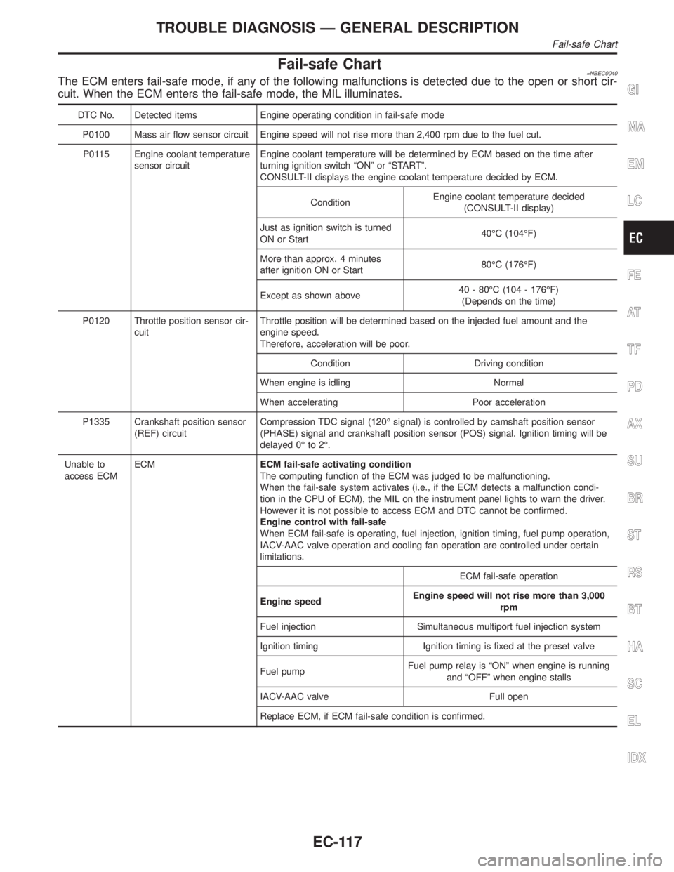
Fail-safe Chart=NBEC0040The ECM enters fail-safe mode, if any of the following malfunctions is detected due to the open or short cir-
cuit. When the ECM enters the fail-safe mode, the MIL illuminates.
DTC No. Detected items Engine operating condition in fail-safe mode
P0100 Mass air flow sensor circuit Engine speed will not rise more than 2,400 rpm due to the fuel cut.
P0115 Engine coolant temperature
sensor circuitEngine coolant temperature will be determined by ECM based on the time after
turning ignition switch ªONº or ªSTARTº.
CONSULT-II displays the engine coolant temperature decided by ECM.
ConditionEngine coolant temperature decided
(CONSULT-II display)
Just as ignition switch is turned
ON or Start40ÉC (104ÉF)
More than approx. 4 minutes
after ignition ON or Start80ÉC (176ÉF)
Except as shown above40 - 80ÉC (104 - 176ÉF)
(Depends on the time)
P0120 Throttle position sensor cir-
cuitThrottle position will be determined based on the injected fuel amount and the
engine speed.
Therefore, acceleration will be poor.
Condition Driving condition
When engine is idling Normal
When accelerating Poor acceleration
P1335 Crankshaft position sensor
(REF) circuitCompression TDC signal (120É signal) is controlled by camshaft position sensor
(PHASE) signal and crankshaft position sensor (POS) signal. Ignition timing will be
delayed 0É to 2É.
Unable to
access ECMECMECM fail-safe activating condition
The computing function of the ECM was judged to be malfunctioning.
When the fail-safe system activates (i.e., if the ECM detects a malfunction condi-
tion in the CPU of ECM), the MIL on the instrument panel lights to warn the driver.
However it is not possible to access ECM and DTC cannot be confirmed.
Engine control with fail-safe
When ECM fail-safe is operating, fuel injection, ignition timing, fuel pump operation,
IACV-AAC valve operation and cooling fan operation are controlled under certain
limitations.
ECM fail-safe operation
Engine speedEngine speed will not rise more than 3,000
rpm
Fuel injection Simultaneous multiport fuel injection system
Ignition timing Ignition timing is fixed at the preset valve
Fuel pumpFuel pump relay is ªONº when engine is running
and ªOFFº when engine stalls
IACV-AAC valve Full open
Replace ECM, if ECM fail-safe condition is confirmed.
GI
MA
EM
LC
FE
AT
TF
PD
AX
SU
BR
ST
RS
BT
HA
SC
EL
IDX
TROUBLE DIAGNOSIS Ð GENERAL DESCRIPTION
Fail-safe Chart
EC-117
Page 654 of 2395
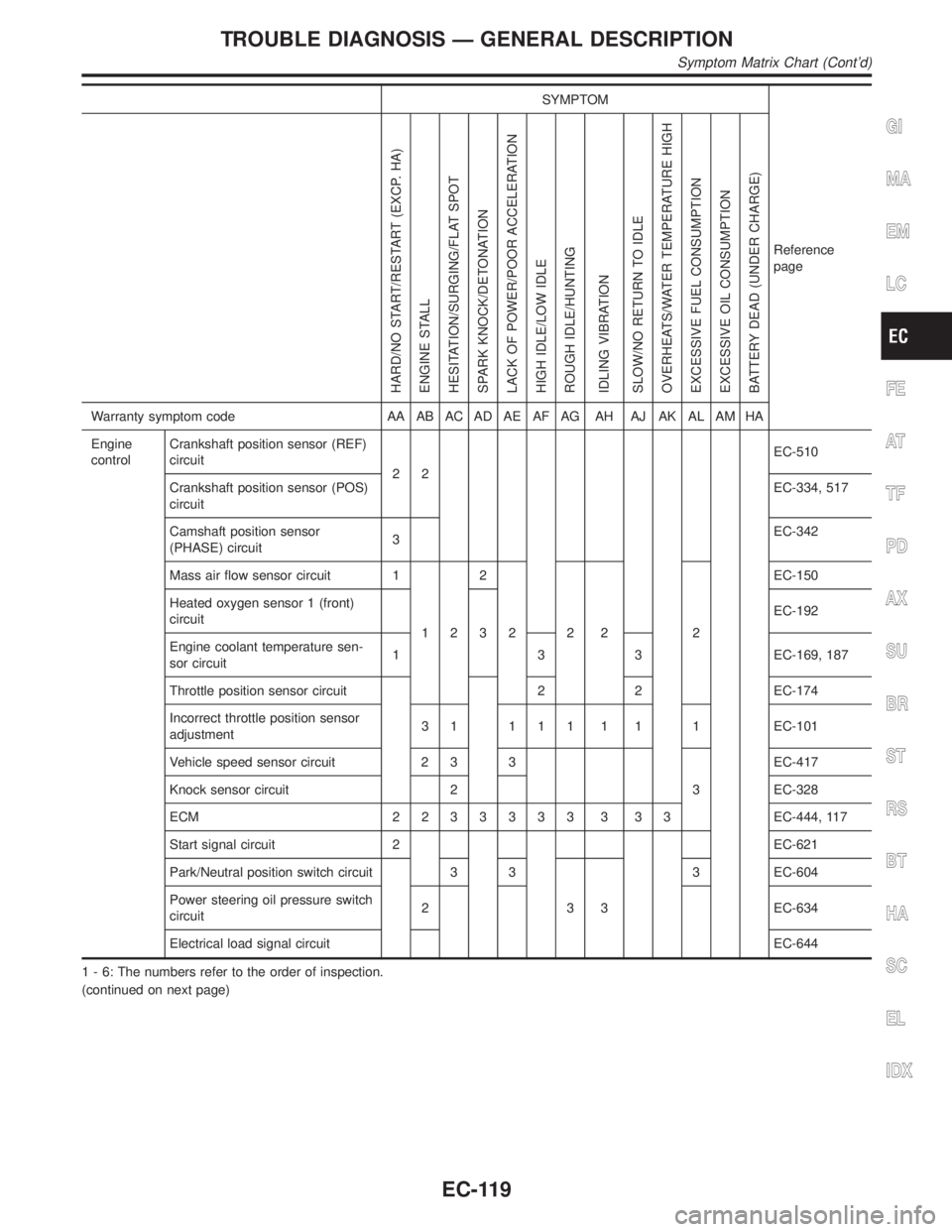
SYMPTOM
Reference
page
HARD/NO START/RESTART (EXCP. HA)
ENGINE STALL
HESITATION/SURGING/FLAT SPOT
SPARK KNOCK/DETONATION
LACK OF POWER/POOR ACCELERATION
HIGH IDLE/LOW IDLE
ROUGH IDLE/HUNTING
IDLING VIBRATION
SLOW/NO RETURN TO IDLE
OVERHEATS/WATER TEMPERATURE HIGH
EXCESSIVE FUEL CONSUMPTION
EXCESSIVE OIL CONSUMPTION
BATTERY DEAD (UNDER CHARGE)
Warranty symptom code AA AB AC AD AE AF AG AH AJ AK AL AM HA
Engine
controlCrankshaft position sensor (REF)
circuit
22EC-510
Crankshaft position sensor (POS)
circuitEC-334, 517
Camshaft position sensor
(PHASE) circuit3EC-342
Mass air flow sensor circuit 1
122
222 2EC-150
Heated oxygen sensor 1 (front)
circuit
3EC-192
Engine coolant temperature sen-
sor circuit1 3 3 EC-169, 187
Throttle position sensor circuit 2 2 EC-174
Incorrect throttle position sensor
adjustment3 1 1 1 1 1 1 1 EC-101
Vehicle speed sensor circuit 2 3 3
3EC-417
Knock sensor circuit 2 EC-328
ECM 2233333 3 33EC-444, 117
Start signal circuit 2 EC-621
Park/Neutral position switch circuit 3 3
333 EC-604
Power steering oil pressure switch
circuit2 EC-634
Electrical load signal circuitEC-644
1 - 6: The numbers refer to the order of inspection.
(continued on next page)
GI
MA
EM
LC
FE
AT
TF
PD
AX
SU
BR
ST
RS
BT
HA
SC
EL
IDX
TROUBLE DIAGNOSIS Ð GENERAL DESCRIPTION
Symptom Matrix Chart (Cont'd)
EC-119
Page 656 of 2395
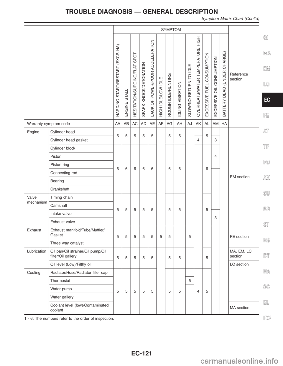
SYMPTOM
Reference
section
HARD/NO START/RESTART (EXCP. HA)
ENGINE STALL
HESITATION/SURGING/FLAT SPOT
SPARK KNOCK/DETONATION
LACK OF POWER/POOR ACCELERATION
HIGH IDLE/LOW IDLE
ROUGH IDLE/HUNTING
IDLING VIBRATION
SLOW/NO RETURN TO IDLE
OVERHEATS/WATER TEMPERATURE HIGH
EXCESSIVE FUEL CONSUMPTION
EXCESSIVE OIL CONSUMPTION
BATTERY DEAD (UNDER CHARGE)
Warranty symptom code AA AB AC AD AE AF AG AH AJ AK AL AM HA
Engine Cylinder head
55555 5 5 5
EM section Cylinder head gasket 4 3
Cylinder block
66666 6 6 64 Piston
Piston ring
Connecting rod
Bearing
Crankshaft
Valve
mechanismTiming chain
55555 5 5 5 Camshaft
Intake valve
3
Exhaust valve
Exhaust Exhaust manifold/Tube/Muffler/
Gasket
5555555 5 FEsection
Three way catalyst
Lubrication Oil pan/Oil strainer/Oil pump/Oil
filter/Oil gallery
55555 5 5 5MA, EM, LC
section
Oil level (Low)/Filthy oilLC section
Cooling Radiator/Hose/Radiator filler cap
55555 5 5 45 Thermostat 5
Water pump
Water gallery
Coolant level (low)/Contaminated
coolantMA section
1 - 6: The numbers refer to the order of inspection.
GI
MA
EM
LC
FE
AT
TF
PD
AX
SU
BR
ST
RS
BT
HA
SC
EL
IDX
TROUBLE DIAGNOSIS Ð GENERAL DESCRIPTION
Symptom Matrix Chart (Cont'd)
EC-121
Page 659 of 2395

MONITOR ITEM CONDITION SPECIFICATION
VENT CONT/VIIgnition switch: ON OFF
HO2S1 HTR (B1)
HO2S1 HTR (B2)IEngine speed: Below 3,600 rpm ON
IEngine speed: Above 3,600 rpm OFF
HO2S2 HTR (B1)
HO2S2 HTR (B2)IIgnition switch: ON (Engine stopped)
IEngine speed: Above 3,200 rpmOFF
IEngine speed: Below 3,200 rpm [After driving for 2 minutes at a speed
of 70 km/h (43 MPH) or more]ON
VC/V BYPASS/V Ignition switch: ON OFF
CAL/LD VALUEIEngine: After warming up
IAir conditioner switch: ªOFFº
IShift lever: ªNº
INo-loadIdle 14.0 - 33.0%
2,500 rpm 12.0 - 25.0%
ABSOL TH´P/SIEngine: After warming up Throttle valve: fully closed 0.0%
IEngine: After warming up
IIgnition switch: ON
(Engine stopped)Throttle valve: fully opened Approx. 80%
MASS AIRFLOWIEngine: After warming up
IAir conditioner switch: ªOFFº
IShift lever: ªNº
INo-loadIdle 2.0 - 6.0 g´m/s
2,500 rpm 7.0 - 20.0 g´m/s
ABSOL PRES/SEIIgnition switch: ON Approx. 4.4V
SWRL CONT S/VIEngine speed: IdleEngine coolant temperature is
between 15ÉC (59ÉF) to 50ÉC
(122ÉF).ON
Engine coolant temperature is above
55ÉC (131ÉF).OFF
SWL CON VC SWIEngine speed: Idle
IEngine coolant temperature is between 15ÉC (59ÉF) to 50ÉC (122ÉF).OFF
IEngine speed: Idle
IEngine coolant temperature is above 55ÉC (131ÉF).ON
INT/V TIM (B1)
INT/V TIM (B2)IEngine: After warming up
IShift lever ªNº
IQuickly depressed accelerator
pedal
INo-loadIdle 0É CA
2,000 rpm Approximately 12 - 18É CA
INT/V SOL (B1)
INT/V SOL (B2)IEngine: After warming up
IShift lever ªNº
IQuickly depressed accelerator
pedal
INo-loadIdle 0%
2,000 rpm Approximately 40%
Major Sensor Reference Graph in Data Monitor
Mode
NBEC0043The following are the major sensor reference graphs in ªDATA MONITORº mode.
THRTL POS SEN, ABSOL TH´P/S, CLSD THL POSNBEC0043S01Below is the data for ªTHRTL POS SENº, ªABSOL TH´P/Sº and ªCLSD THL POSº when depressing the accel-
erator pedal with the ignition switch ªONº.
The signal of ªTHRTL POS SENº and ªABSOL TH´P/Sº should rise gradually without any intermittent drop or
rise after ªCLSD THL POSº is changed from ªONº to ªOFFº.
TROUBLE DIAGNOSIS Ð GENERAL DESCRIPTION
CONSULT-II Reference Value in Data Monitor Mode (Cont'd)
EC-124
Page 665 of 2395
![INFINITI QX4 2001 Factory Owners Guide TERMI-
NAL
NO.WIRE
COLORITEM CONDITION DATA (DC Voltage)
25 W/G Tachometer[Engine is running]
IWarm-up condition
IIdle speed7-8VH
SEF579X
[Engine is running]
IWarm-up condition
IEngine speed is 2,500 INFINITI QX4 2001 Factory Owners Guide TERMI-
NAL
NO.WIRE
COLORITEM CONDITION DATA (DC Voltage)
25 W/G Tachometer[Engine is running]
IWarm-up condition
IIdle speed7-8VH
SEF579X
[Engine is running]
IWarm-up condition
IEngine speed is 2,500](/img/42/57027/w960_57027-664.png)
TERMI-
NAL
NO.WIRE
COLORITEM CONDITION DATA (DC Voltage)
25 W/G Tachometer[Engine is running]
IWarm-up condition
IIdle speed7-8VH
SEF579X
[Engine is running]
IWarm-up condition
IEngine speed is 2,500 rpm.7-8VH
SEF580X
26 L/BECM relay
(Self shutt-off)[Engine is running]
[Ignition switch ªOFFº]
IFor a few seconds after turning ignition switch
ªOFFº0 - 1.5V
[Ignition switch ªOFFº]
IA few seconds passed after turning ignition
switch ªOFFºBATTERY VOLTAGE
(11 - 14V)
27 LG Air conditioner relay[Engine is running]
IBoth A/C switch and blower switch are ªONº
(Compressor is operating).0 - 1.0V
[Engine is running]
IA/C switch is ªOFFº.BATTERY VOLTAGE
(11 - 14V)
28 R/L Fuel pump relay[Ignition switch ªONº]
IFor 1 second after turning ignition switch ªONº
[Engine is running]0 - 1.5V
[Ignition switch ªONº]
I1 second passed after turning ignition switch
ªONº.BATTERY VOLTAGE
(11 - 14V)
29 GSwirl control valve con-
trol solenoid valve[Engine is running]
IIdle speed
IEngine coolant temperature is between 15 to
50ÉC (59 to 122ÉF).0 - 1.0V
[Engine is running]
IIdle speed
IEngine coolant temperature is above 55ÉC
(131ÉF).BATTERY VOLTAGE
(11 - 14V)
38 OR MIL[Ignition switch ªONº]0 - 1.0V
[Engine is running]
IIdle speedBATTERY VOLTAGE
(11 - 14V)
39 G/WVacuum cut valve
bypass valve[Ignition switch ªONº]BATTERY VOLTAGE
(11 - 14V)
40 G/YEVAP canister vent
control valve[Ignition switch ªONº]BATTERY VOLTAGE
(11 - 14V)
TROUBLE DIAGNOSIS Ð GENERAL DESCRIPTION
ECM Terminals and Reference Value (Cont'd)
EC-130
Page 666 of 2395
![INFINITI QX4 2001 Factory Owners Guide TERMI-
NAL
NO.WIRE
COLORITEM CONDITION DATA (DC Voltage)
42 B/Y Start signal[Ignition switch ªONº]Approximately 0V
[Ignition switch ªSTARTº]9 - 12V
43 R Ignition switch[Ignition switch ªOFFº]0V
INFINITI QX4 2001 Factory Owners Guide TERMI-
NAL
NO.WIRE
COLORITEM CONDITION DATA (DC Voltage)
42 B/Y Start signal[Ignition switch ªONº]Approximately 0V
[Ignition switch ªSTARTº]9 - 12V
43 R Ignition switch[Ignition switch ªOFFº]0V](/img/42/57027/w960_57027-665.png)
TERMI-
NAL
NO.WIRE
COLORITEM CONDITION DATA (DC Voltage)
42 B/Y Start signal[Ignition switch ªONº]Approximately 0V
[Ignition switch ªSTARTº]9 - 12V
43 R Ignition switch[Ignition switch ªOFFº]0V
[Ignition switch ªONº]BATTERY VOLTAGE
(11 - 14V)
44 L PNP switch[Ignition switch ªONº]
IGear position is ªPº or ªNº.Approximately 0V
[Ignition switch ªONº]
IExcept the above gear positionBATTERY VOLTAGE
(11 - 14V)
45 B/RAir conditioner switch
signal[Engine is running]
IBoth A/C switch and blower switch are ªONº.Approximately 0V
[Engine is running]
IA/C switch is ªOFFº.Approximately 5V
47 R/BPower steering oil
pressure switch[Engine is running]
ISteering wheel is being turned.0 - 1.0V
[Engine is running]
ISteering wheel is not being turned.Approximately 5V
48 B ECM ground[Engine is running]
IIdle speedEngine ground
51 BR A/C cut signal[Engine is running]
IAir conditioner is operating.0 - 0.5V
52 PU Electrical load signal[Engine is running]
IRear window defogger: ON
IHi-beam headlamp: ONBATTERY VOLTAGE
(11 - 14V)
[Engine is running]
IElectrical load: OFF0V
55 W/BSwirl control valve con-
trol vacuum check
switch[Engine is running]
IIdle speed
IEngine coolant temperature is between 15 to
50ÉC (59 to 122ÉF).Approximately 5V
[Engine is running]
IIdle speed
IEngine coolant temperature is above 55ÉC
(131ÉF).0 - 1.0V
56 OR/LThrottle position switch
(Closed position)[Engine is running]
IAccelerator pedal fully releasedBATTERY VOLTAGE
(11 - 14V)
[Engine is running]
IAccelerator pedal depressedApproximately 0V
57 B ECM ground[Engine is running]
IIdle speedEngine ground
58 B/P Sensors' ground[Engine is running]
IWarm-up condition
IIdle speedApproximately 0V
59 BFuel level sensor
ground[Engine is running]
IIdle speedApproximately 0V
GI
MA
EM
LC
FE
AT
TF
PD
AX
SU
BR
ST
RS
BT
HA
SC
EL
IDX
TROUBLE DIAGNOSIS Ð GENERAL DESCRIPTION
ECM Terminals and Reference Value (Cont'd)
EC-131
Page 667 of 2395
![INFINITI QX4 2001 Factory Owners Guide TERMI-
NAL
NO.WIRE
COLORITEM CONDITION DATA (DC Voltage)
61 OR Mass air flow sensor[Engine is running]
IWarm-up condition
IIdle speed1.2 - 1.8V
[Engine is running]
IWarm-up condition
IEngine speed is INFINITI QX4 2001 Factory Owners Guide TERMI-
NAL
NO.WIRE
COLORITEM CONDITION DATA (DC Voltage)
61 OR Mass air flow sensor[Engine is running]
IWarm-up condition
IIdle speed1.2 - 1.8V
[Engine is running]
IWarm-up condition
IEngine speed is](/img/42/57027/w960_57027-666.png)
TERMI-
NAL
NO.WIRE
COLORITEM CONDITION DATA (DC Voltage)
61 OR Mass air flow sensor[Engine is running]
IWarm-up condition
IIdle speed1.2 - 1.8V
[Engine is running]
IWarm-up condition
IEngine speed is 2,500 rpm.1.6 - 2.2V
62 G/BHeated oxygen sensor
1 (front) (bank 2)[Engine is running]
IWarm-up condition
IEngine speed is 2,000 rpm.0 - Approximately 1.0V (Peri-
odically change)
SEF059V
63 GHeated oxygen sensor
1 (front) (bank 1)[Engine is running]
IWarm-up condition
IEngine speed is 2,000 rpm.0 - Approximately 1.0V (Peri-
odically change)
SEF059V
64 Y/PUIntake air temperature
sensor[Engine is running]Approximately 0 - 4.8V
Output voltage varies with
intake air temperature.
65
75LG
LGCrankshaft position
sensor (REF)[Engine is running]
IWarm-up condition
IIdle speedApproximately 2.3VH
(AC voltage)
SEF581X
66
76L
LCamshaft position sen-
sor (PHASE)[Engine is running]
IWarm-up condition
IIdle speedApproximately 4.2VH
(AC voltage)
SEF582X
12
67W/RPower supply for ECM
(Buck-up)[Ignition switch ªOFFº]BATTERY VOLTAGE
(11 - 14V)
70 LG/REngine coolant tem-
perature sensor[Engine is running]Approximately 0 - 4.8V
Output voltage varies with
engine coolant temperature.
TROUBLE DIAGNOSIS Ð GENERAL DESCRIPTION
ECM Terminals and Reference Value (Cont'd)
EC-132
Page 671 of 2395
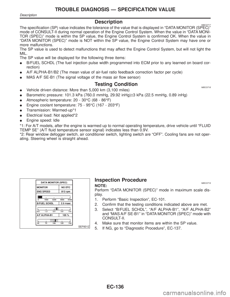
DescriptionNBEC0717The specification (SP) value indicates the tolerance of the value that is displayed in ªDATA MONITOR (SPEC)º
mode of CONSULT-II during normal operation of the Engine Control System. When the value in ªDATA MONI-
TOR (SPEC)º mode is within the SP value, the Engine Control System is confirmed OK. When the value in
ªDATA MONITOR (SPEC)º mode is NOT within the SP value, the Engine Control System may have one or
more malfunctions.
The SP value is used to detect malfunctions that may affect the Engine Control System, but will not light the
MIL.
The SP value will be displayed for the following three items:
IB/FUEL SCHDL (The fuel injection pulse width programmed into ECM prior to any learned on board cor-
rection)
IA/F ALPHA-B1/B2 (The mean value of air-fuel ratio feedback correction factor per cycle)
IMAS A/F SE-B1 (The signal voltage of the mass air flow sensor)
Testing ConditionNBEC0718IVehicle driven distance: More than 5,000 km (3,100 miles)
IBarometric pressure: 101.3 kPa (760.0 mmHg, 29.92 inHg)±3 kPa (22.5 mmHg, 0.89 inHg)
IAtmospheric temperature: 20 - 30ÉC (68 - 86ÉF)
IEngine coolant temperature: 75 - 95ÉC (167 - 203ÉF)
ITransmission: Warmed-up*1
IElectrical load: Not applied*2
IEngine speed: Idle
*1: For A/T models, after the engine is warmed up to normal operating temperature, drive vehicle until ªFLUID
TEMP SEº (A/T fluid temperature sensor signal) indicates less than 0.9V.
*2: Rear window defogger switch, air conditioner switch, lighting switch are ªOFFº. Cooling fans are not oper-
ating. Steering wheel is straight ahead.
SEF601Z
Inspection ProcedureNBEC0719NOTE:
Perform ªDATA MONITOR (SPEC)º mode in maximum scale dis-
play.
1. Perform ªBasic Inspectionº, EC-101.
2. Confirm that the testing conditions indicated above are met.
3. Select ªB/FUEL SCHDLº, ªA/F ALPHA-B1º, ªA/F ALPHA-B2º
and ªMAS A/F SE-B1º in ªDATA MONITOR (SPEC)º mode with
CONSULT-II.
4. Make sure that monitor items are within the SP value.
5. If NG, go to ªDiagnostic Procedureº, EC-137.
TROUBLE DIAGNOSIS Ð SPECIFICATION VALUE
Description
EC-136