length INFINITI QX4 2001 Factory Owner's Guide
[x] Cancel search | Manufacturer: INFINITI, Model Year: 2001, Model line: QX4, Model: INFINITI QX4 2001Pages: 2395, PDF Size: 43.2 MB
Page 1964 of 2395

Fusible link ......................................................EL-16
G
Garage jack and safety stand .........................GI-46
Gauges............................................................EL-94
Generator - See Alternator .............................SC-28
Generic scan tool (GST) ................................EC-95
Glass ...............................................................BT-18
Glass hatch opener, electric .........................EL-178
Grease ............................................................MA-11
Ground distribution..........................................EL-17
H
Harness connector ............................................EL-5
Harness connector inspection .........................GI-21
Harness layout ..............................................EL-440
Hazard warning lamp ......................................EL-75
Headlamp ........................................................EL-31
Headlamp aiming control ................................EL-59
Headlining - See Roof trim .............................BT-32
Heated seat .......................................BT-43, EL-183
Height (Dimensions) ........................................GI-43
HFC134a (R134a) system precaution .............HA-2
HFC134a (R134a) system service
procedure ..................................................HA-144
HFC134a (R134a) system service tools ........HA-11
HFC134a system service equipment
precaution .....................................................HA-7
High clutch.....................................................AT-317
H/LAMP - Wiring diagram ...............................EL-36
Hood................................................................BT-12
Horn ..............................................................EL-147
HORN - Wiring diagram................................EL-147
How to erase DTC for OBD system...............EC-72
HSEAT - Wiring diagram...............................EL-183
I
IACV-AAC valve ...........................................EC-422
IATS - Wiring diagram ..................................EC-166
Identification .....................................................HA-4
Identification plate............................................GI-42
Idle air control valve (IACV) .........................EC-422
Idle mixture ratio.............................................EC-43
Idle speed .......................................................EC-43
IGN/SG - Wiring diagram .............................EC-501
Ignition control system .................................EC-499
Ignition timing .................................................EC-43
ILL - Wiring diagram .......................................EL-83
Illumination ......................................................EL-80
In vehicle sensor ..........................................HA-132
INFINITI COMMUNICATOR..........................EL-348
Infiniti communicator (IVCS) .........................EL-348
INJECT - Wiring diagram .............................EC-617
Injector ..........................................................EC-616Injector removal and installation ....................EC-41
Instrument panel .............................................BT-21
INT/L - Wiring diagram....................................EL-91
Intake air temparature sensor ......................EC-164
Intake door control linkage adjustment ..........HA-94
Intake door motor ...........................................HA-87
Intake manifold...............................................EM-12
Intake sensor ................................................HA-139
Integrated homelink transmitter ....................EL-325
Interior .............................................................BT-28
Interior lamp ....................................................EL-88
Interior lamp on-off control ..............................EL-89
Internal gear (Transfer) .................................TF-134
IVC-L - Wiring diagram.................................EC-453
IVC-R - Wiring diagram ................................EC-453
IVCS - Wiring diagram ..................................EL-359
IVCS-L - Wiring diagram ..............................EC-485
IVCS-R - Wiring diagram .............................EC-485
IVIS (Infiniti vehicle immobilizer
system) ......................................................EL-328
IVIS (Infiniti vehicle immobilizer sys-
tem) precautions ............................................GI-3
J
Jacking points ..................................................GI-45
Journal bearing assembly (propeller
shaft) .............................................................PD-9
Journal bearing disassembly (propeller
shaft) .............................................................PD-8
Junction box (J/B).........................................Foldout
K
Keyless entry system - See Multi-re-
mote control system ..................................EL-270
Knock sensor (KS) .......................................EC-328
Knuckle spindle ................................................AX-9
KS - Wiring diagram .....................................EC-330
L
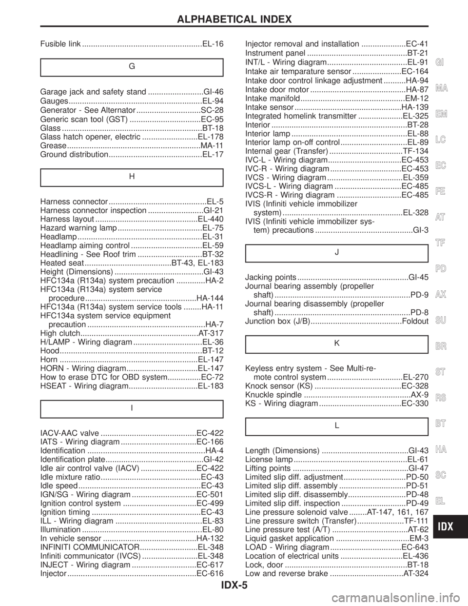
Length (Dimensions) .......................................GI-43
License lamp ...................................................EL-61
Lifting points ....................................................GI-47
Limited slip diff. adjustment ............................PD-50
Limited slip diff. assembly ..............................PD-51
Limited slip diff. disassembly..........................PD-48
Limited slip diff. inspection .............................PD-49
Line pressure solenoid valve ........AT-147, 161, 167
Line pressure switch (Transfer) .....................TF-111
Line pressure test (A/T) ..................................AT-62
Liquid gasket application .................................EM-3
LOAD - Wiring diagram ................................EC-643
Location of electrical units ............................EL-436
Lock, door .......................................................BT-18
Low and reverse brake .................................AT-324
GI
MA
EM
LC
EC
FE
AT
TF
PD
AX
SU
BR
ST
RS
BT
HA
SC
EL
ALPHABETICAL INDEX
IDX-5
Page 2036 of 2395

Service Data and Specifications (SDS)
GENERAL SPECIFICATIONS=NBPD00092WD ModelNBPD0009S01
TransmissionA/T
Propeller shaft model3F80B-2BJ
Number of joints3
Coupling method with transmissionFlange type
Type of journal bearings Solid type (disassembly type Ð without birfield joint Ð)
Distance between yokes mm (in)80 (3.15)
Shaft length (Spider to spider) mm (in)1st 650 (25.59)
2nd 749 (29.49)
Shaft outer diameter mm (in)1st 75 (2.95)
2nd 65 (2.56)
4WD ModelNBPD0009S02
LocationFront Rear
Propeller shaft model 2F71H 2S80B-T
Number of joints2
Coupling method with transmission Flange type Sleeve type
Type of journal bearingsSolid type (disassembly type)
Distance between yokes mm (in) 71 (2.80) 80 (3.15)
Shaft length (Spider to spider) mm (in) 553 (21.77) 927 (36.50)
Shaft outer diameter mm (in) 50.8 (2.000) 75 and 63.5 (2.95 and 2.500)
SERVICE DATANBPD0010Unit: mm (in)
Propeller shaft runout limit0.6 (0.024)
Journal axial play0.02 (0.0008) or less
SNAP RING (80B)NBPD0011Unit: mm (in)
Thickness Color Part number*
1.99 (0.0783) White 37146-C9400
2.02 (0.0795) Yellow 37147-C9400
2.05 (0.0807) Red 37148-C9400
2.08 (0.0819) Green 37149-C9400
2.11 (0.0831) Blue 37150-C9400
2.14 (0.0843) Light brown 37151-C9400
2.17 (0.0854) Black 37152-C9400
2.20 (0.0866) No paint 37153-C9400
*: Always check with the Parts Department for the latest parts information.
GI
MA
EM
LC
EC
FE
AT
TF
AX
SU
BR
ST
RS
BT
HA
SC
EL
IDX
PROPELLER SHAFT
Service Data and Specifications (SDS)
PD-11
Page 2062 of 2395
![INFINITI QX4 2001 Factory Owners Guide Total Preload AdjustmentNBPD0022S05
Total preload N´m (kg-cm, in-lb) P1+ [0.3 - 1.5 (3 - 15, 2.6 - 13.0)]
Ring gear backlash mm (in) 0.10 - 0.15 (0.0039 - 0.0059)
P1: Drive pinion preload
Drive Pinio INFINITI QX4 2001 Factory Owners Guide Total Preload AdjustmentNBPD0022S05
Total preload N´m (kg-cm, in-lb) P1+ [0.3 - 1.5 (3 - 15, 2.6 - 13.0)]
Ring gear backlash mm (in) 0.10 - 0.15 (0.0039 - 0.0059)
P1: Drive pinion preload
Drive Pinio](/img/42/57027/w960_57027-2061.png)
Total Preload AdjustmentNBPD0022S05
Total preload N´m (kg-cm, in-lb) P1+ [0.3 - 1.5 (3 - 15, 2.6 - 13.0)]
Ring gear backlash mm (in) 0.10 - 0.15 (0.0039 - 0.0059)
P1: Drive pinion preload
Drive Pinion Height AdjustmentNBPD0022S06
Available pin-
ion height
adjusting
washersThickness mm (in) Part number*
3.09 (0.1217)
3.12 (0.1228)
3.15 (0.1240)
3.18 (0.1252)
3.21 (0.1264)
3.24 (0.1276)
3.27 (0.1287)
3.30 (0.1299)
3.33 (0.1311)
3.36 (0.1323)
3.39 (0.1335)
3.42 (0.1346)
3.45 (0.1358)
3.48 (0.1370)
3.51 (0.1382)
3.54 (0.1394)
3.57 (0.1406)
3.60 (0.1417)
3.63 (0.1429)
3.66 (0.1441)38154-P6017
38154-P6018
38154-P6019
38154-P6020
38154-P6021
38154-P6022
38154-P6023
38154-P6024
38154-P6025
38154-P6026
38154-P6027
38154-P6028
38154-P6029
38154-P6030
38154-P6031
38154-P6032
38154-P6033
38154-P6034
38154-P6035
38154-P6036
*: Always check with the Parts Department for the latest parts information.
Drive Pinion Preload AdjustmentNBPD0022S07
Drive pinion bearing preload adjusting method Adjusting washer and spacer
Drive pinion preload with front oil seal N´m (kg-cm, in-lb) [P
1] 1.1 - 1.4 (11 - 14, 9.5 - 12.2)
Available drive
pinion bearing
preload adjust-
ing washersThickness mm (in) Part number*
3.81 (0.1500)
3.83 (0.1508)
3.85 (0.1516)
3.87 (0.1524)
3.89 (0.1531)
3.91 (0.1539)
3.93 (0.1547)
3.95 (0.1555)
3.97 (0.1563)
3.99 (0.1571)
4.01 (0.1579)
4.03 (0.1587)
4.05 (0.1594)
4.07 (0.1602)
4.09 (0.1610)38125-61001
38126-61001
38127-61001
38128-61001
38129-61001
38130-61001
38131-61001
38132-61001
38133-61001
38134-61001
38135-61001
38136-61001
38137-61001
38138-61001
38139-61001
Available drive
pinion bearing
preload adjust-
ing spacersLength mm (in) Part number*
54.50 (2.1457)
54.80 (2.1575)
55.10 (2.1693)
55.40 (2.1811)
55.70 (2.1929)
56.00 (2.2047)38165-B4000
38165-B4001
38165-B4002
38165-B4003
38165-B4004
38165-61001
*: Always check with the Parts Department for the latest parts information.
GI
MA
EM
LC
EC
FE
AT
TF
AX
SU
BR
ST
RS
BT
HA
SC
EL
IDX
FRONT FINAL DRIVER200A
Service Data and Specifications (SDS) (Cont'd)
PD-37
Page 2075 of 2395

SPD381A
4. Measure frictional surfaces and projected portions of friction
disc, friction plate, spring plate, and determine each part's dif-
ferences to see if the specified wear limit has been exceeded.
If any part has worn beyond the wear limit, and deformed or
fatigued, replace it with a new one that is the same thickness as
the projected portion.
Wear limit:
0.1 mm (0.004 in) or less
AþB=Wearlimit mm (in)
I: Measuring points
A: Projected portion
B: Frictional surface
SPD383A
SPD417
ADJUSTMENTNBPD0038Friction Disc and Friction Plate End PlayNBPD0038S01End play of friction disc and friction plate can be calculated by using
following equation and should be adjusted within following range.
Adjustment can be made by selecting friction disc having two dif-
ferent thicknesses.
End play E:
0.05 - 0.15 mm (0.0020 - 0.0059 in)
E=Aþ(B+C)
A: Length of differential case contact surface to differential case
inner bottom.
B: Total thickness of friction discs, friction plates, spring disc and
spring plate in differential case on one side.
C: Length of differential case contact surface to back side of side
gear.
1. Measure values of ªAº.
Standard length A:
49.50 - 49.55 mm (1.9488 - 1.9508 in)
SPD420
2. Measure thickness of each disc and plate.
Total thickness ªBº:
19.24 - 20.26 mm (0.7575 - 0.7976 in)
REAR FINAL DRIVEH233B
Limited Slip Differential (Cont'd)
PD-50
Page 2097 of 2395

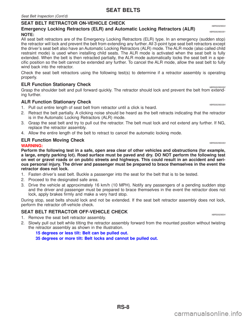
SEAT BELT RETRACTOR ON-VEHICLE CHECKNBRS0029S03Emergency Locking Retractors (ELR) and Automatic Locking Retractors (ALR)NBRS0029S0301NOTE:
All seat belt retractors are of the Emergency Locking Retractors (ELR) type. In an emergency (sudden stop)
the retractor will lock and prevent the belt from extending any further. All 3-point type seat belt retractors except
the driver's seat belt also have an Automatic Locking Retractors (ALR) mode. The ALR mode (also called child
restraint mode) is used when installing child seats. The ALR mode is activated when the seat belt is fully
extended. When the belt is then retracted partially, the ALR mode automatically locks the seat belt in a spe-
cific position so the belt cannot be extended any further. To cancel the ALR mode, allow the seat belt to fully
wind back into the retractor.
Check the seat belt retractors using the following test(s) to determine if a retractor assembly is operating
properly.
ELR Function Stationary CheckNBRS0029S0302Grasp the shoulder belt and pull forward quickly. The retractor should lock and prevent the belt from extend-
ing further.
ALR Function Stationary CheckNBRS0029S03041. Pull out entire length of seat belt from retractor until a click is heard.
2. Retract the belt partially. A clicking noise should be heard as the belt retracts indicating that the retractor
is in the Automatic Locking Retractors (ALR) mode.
3. Grasp the seat belt and try to pull out the retractor. The belt must lock and not extend any further. If NG,
replace the retractor assembly.
4. Allow the entire length of the belt to retract to cancel the automatic locking mode.
ELR Function Moving CheckNBRS0029S0303WARNING:
Perform the following test in a safe, open area clear of other vehicles and obstructions (for example,
a large, empty parking lot). Road surface must be paved and dry. DO NOT perform the following test
on wet or gravel roads or on public streets and highways. This could result in an accident and seri-
ous personal injury. The driver and passenger must be prepared to brace themselves in the event the
retractor does not lock.
1. Fasten driver's seat belt. Buckle a passenger into the seat for the belt that is to be tested.
2. Proceed to the designated safe area.
3. Drive the vehicle at approximately 16 km/h (10 MPH). Notify any passengers of a pending sudden stop
and the driver and passenger must be prepared to brace themselves in the event the retractor does not
lock, apply brakes firmly and make a very hard stop.
During stop, seat belts should lock and not be extended. If the seat belt retractor assembly does not lock,
perform the retractor off-vehicle check.
SEAT BELT RETRACTOR OFF-VEHICLE CHECKNBRS0029S041. Remove the seat belt retractor assembly.
2. Slowly pull out belt while tilting the retractor assembly forward from the mounted position without twisting
the retractor assembly as shown in the illustration.
15 degrees or less tilt: Belt can be pulled out.
35 degrees or more tilt: Belt locks and cannot be pulled out.
SEAT BELTS
Seat Belt Inspection (Cont'd)
RS-8
Page 2180 of 2395

BatteryNBSC0014
Applied area USA Canada
Type80D26R
Capacity V-AH12-65
Cold cranking current A
(For reference value)582
StarterNBSC0015
TypeM0T50371
MITSUBISHI make
Reduction gear type
System voltage12V
No-loadTerminal voltage 11.0V
Current Less than 90A
Revolution More than 2,700 rpm
Minimum diameter of commutator28.8 mm (1.134 in)
Minimum length of brush7.0 mm (0.276 in)
Brush spring tension18.3 - 24.8 N (1.87 - 2.53 kg, 4.11 - 5.58 lb)
Movement ªº in height of pinion assembly 0.5 - 2.0 mm (0.020 - 0.079 in)
AlternatorNBSC0016
TypeLR1110-712
HITACHI make
Nominal rating12V-110A
Ground polarityNegative
Minimum revolution under no-load (When 13.5 volts is applied) Less than 1,000 rpm
Hot output current (When 13.5 volts is applied)More than 35A/1,300 rpm
More than 85A/2,500 rpm
More than 110A/5,000 rpm
Regulated output voltage14.1 - 14.7V
Minimum length of brushMore than 6.0 mm (0.236 in)
Brush spring pressure 1.0 - 3.43 N (102 - 350 g, 3.60 - 12.34 oz)
Slip ring minimum outer diameter More than 26.0 mm (1.024 in)
Rotor (Field coil) resistance2.31W
GI
MA
EM
LC
EC
FE
AT
TF
PD
AX
SU
BR
ST
RS
BT
HA
EL
IDX
SERVICE DATA AND SPECIFICATIONS (SDS)
Battery
SC-29
Page 2195 of 2395

SST606C
SST607C
InspectionNBST0019IWhen steering wheel does not turn smoothly, check the steer-
ing column as follows and replace damaged parts.
a) Check column bearings for damage and unevenness. Lubri-
cate with recommended multi-purpose grease or replace steer-
ing column as an assembly, if necessary.
b) Check steering column lower shaft for deformation and break-
age. Replace if necessary.
IWhen the vehicle comes into a light collision, check length ªL
1º,
ªL
2º and ªL3º.
Steering column length ªL
1º:
716.7 - 718.7 mm (28.22 - 28.30 in)
Steering column lower shaft length ªL
2º:
178 - 180 mm (7.01 - 7.09 in)
Steering column upper joint length ªL
3º:
430.7 - 432.7 mm (16.96 - 17.04 in)
If out of the specifications, replace steering column upper joint
or steering column as an assembly.
SST582BE
TILT MECHANISMNBST0019S01After installing steering column, check tilt mechanism operation.
STEERING WHEEL AND STEERING COLUMN
Inspection
ST-14
Page 2205 of 2395

SST609C
14. Ensure that the rack is centered. Install rear cover cap so that
its protrusion is positioned as shown in figure.
Be careful not to damage worm ring and oil seal.
15. Install retainer, spring and adjusting screw temporarily.
SST135C
16. Install new lock plate.
IAttach lock plate 2 to side rod inner socket 1.
IApply locking sealant to inner socket threads 3.
Screw inner socket into rack 4 and tighten to specified torque.
IClinch two places of lock plate at rack's groove.
CAUTION:
To prevent scratching the boot, remove burrs from lock plate.
SST655C
17. Tighten outer socket lock nut.
Tie-rod length ªLº:
Refer to SDS, ST-33.
18. Measure rack stroke.
Rack stroke ªSº:
Refer to SDS, ST-33.
SST967A
19. Before installing boot, coat the contact surfaces between boot
and tie-rod with grease.
SST619C
AdjustmentNBST0031Adjust pinion rotating torque as follows:
1. Set rack to the neutral position without fluid in the gear.
2. Coat the adjusting screw with locking sealant and screw it in.
3. Lightly tighten lock nut.
4. Tighten adjusting screw to a torque of 4.9 to 5.9 N´m (50 to 60
kg-cm, 43 to 52 in-lb).
5. Loosen adjusting screw, then retighten it to 0.2 N´m (2 kg-cm,
1.7 in-lb).
POWER STEERING GEAR AND LINKAGE
Assembly (Cont'd)
ST-24
Page 2213 of 2395

General SpecificationsNBST0037
Applied modelAll
Steering modelPower steering
Steering gear typePR32K
Steering overall gear ratio 17.2
Turns of steering wheel
(Lock to lock)3.09
Steering column type Collapsible, tilt
Steering WheelNBST0038Unit: mm (in)
Steering wheel axial play0 (0)
Steering wheel play35 (1.38) or less
Movement of gear housing±2(±0.08) or less
Steering ColumnNBST0039Unit: mm (in)
Steering column length ªL1º 716.7 - 718.7 (28.22 - 28.30)
Steering column lower shaft length ªL
2º 178 - 180 (7.01 - 7.09)
Steering column upper joint length ªL
3º 430.7 - 432.7 (16.96 - 17.04)
SST739C
Steering Transfer GearNBST0041
Rotating torque0.25 - 0.69 N´m (2.5 - 7.0 kg-cm, 2.2 - 6.1 in-lb)
SERVICE DATA AND SPECIFICATIONS (SDS)
General Specifications
ST-32
Page 2214 of 2395

Steering Gear and LinkageNBST0040
Applied modelAll
Steering gear typePR32K
Tie-rod outer ball jointSwinging force at cotter pin hole: ªAº 4.9 - 47.1 N (0.5 - 4.8 kg, 1.1 - 10.6 lb)
Rotating torque: ªBº 0.3 - 2.9 N´m (3 - 30 kg-cm, 2.6 - 26.0 in-lb)
Axial end play: ªCº 0.1 mm (0.004 in) or less
Tie-rod inner ball jointSwinging force*: ªAº 3.9 - 32.4 N (0.4 - 3.3 kg, 0.9 - 7.3 lb)
Axial end play: ªCº 0.3 mm (0.012 in) or less
Tie-rod standard length ªLº200 mm (7.87 in)
Rack stroke ªSº72.0 mm (2.835 in)
Pinion gear preload without
gear fluidLock to lock
Average rotating torque0.78 - 1.47 N´m (8.0 - 15.0 kg-cm, 6.9 - 13.0 in-lb)
Within±100É from the neutral position
Maximum torque variation0.4 N´m (4 kg-cm, 3.5 in-lb)
Outside the above range
Maximum torque variation0.6 N´m (6 kg-cm, 5.2 in-lb)
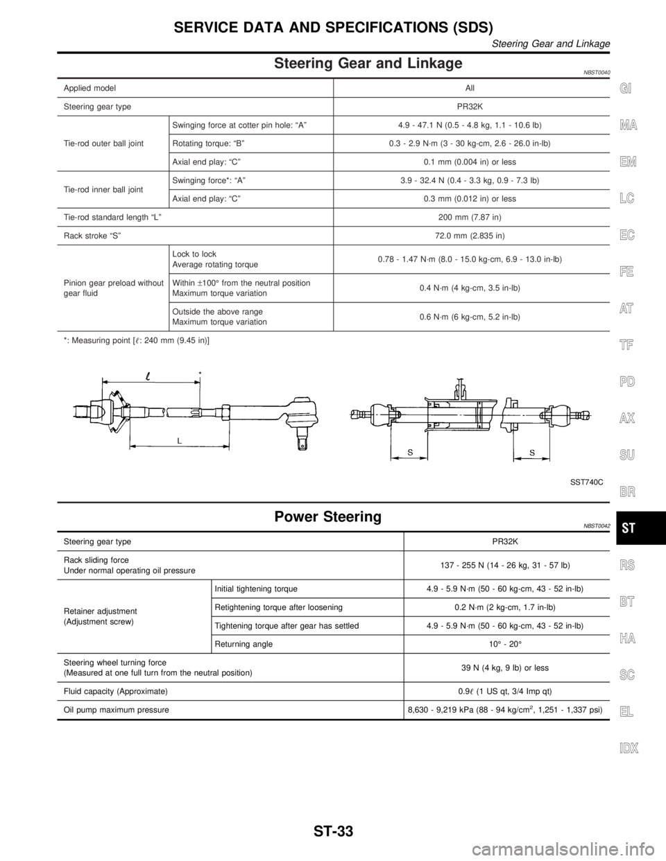
*: Measuring point [: 240 mm (9.45 in)]
SST740C
Power SteeringNBST0042
Steering gear typePR32K
Rack sliding force
Under normal operating oil pressure137 - 255 N (14 - 26 kg, 31 - 57 lb)
Retainer adjustment
(Adjustment screw)Initial tightening torque 4.9 - 5.9 N´m (50 - 60 kg-cm, 43 - 52 in-lb)
Retightening torque after loosening 0.2 N´m (2 kg-cm, 1.7 in-lb)
Tightening torque after gear has settled 4.9 - 5.9 N´m (50 - 60 kg-cm, 43 - 52 in-lb)
Returning angle 10É - 20É
Steering wheel turning force
(Measured at one full turn from the neutral position)39 N (4 kg, 9 lb) or less
Fluid capacity (Approximate)0.9(1 US qt, 3/4 Imp qt)
Oil pump maximum pressure 8,630 - 9,219 kPa (88 - 94 kg/cm
2, 1,251 - 1,337 psi)
GI
MA
EM
LC
EC
FE
AT
TF
PD
AX
SU
BR
RS
BT
HA
SC
EL
IDX
SERVICE DATA AND SPECIFICATIONS (SDS)
Steering Gear and Linkage
ST-33