diagram INFINITI QX4 2001 Factory Workshop Manual
[x] Cancel search | Manufacturer: INFINITI, Model Year: 2001, Model line: QX4, Model: INFINITI QX4 2001Pages: 2395, PDF Size: 43.2 MB
Page 514 of 2395

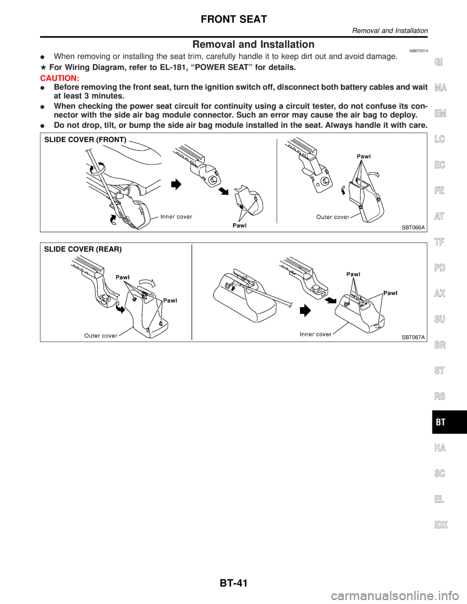
Removal and InstallationNBBT0014IWhen removing or installing the seat trim, carefully handle it to keep dirt out and avoid damage.
HFor Wiring Diagram, refer to EL-181, ªPOWER SEATº for details.
CAUTION:
IBefore removing the front seat, turn the ignition switch off, disconnect both battery cables and wait
at least 3 minutes.
IWhen checking the power seat circuit for continuity using a circuit tester, do not confuse its con-
nector with the side air bag module connector. Such an error may cause the air bag to deploy.
IDo not drop, tilt, or bump the side air bag module installed in the seat. Always handle it with care.
SBT066A
SBT067A
GI
MA
EM
LC
EC
FE
AT
TF
PD
AX
SU
BR
ST
RS
HA
SC
EL
IDX
FRONT SEAT
Removal and Installation
BT-41
Page 516 of 2395

HEATED SEAT=NBBT0014S03IWhen handling seat, be extremely careful not to scratch heating unit.
ITo replace heating unit, seat trim and pad should be separated.
IDo not use any organic solvent, such as thinner, benzene, alcohol, gasoline, etc. to clean trims.
HFor Wiring Diagram, refer to EL-183, ªHEATED SEATº for details.
GI
MA
EM
LC
EC
FE
AT
TF
PD
AX
SU
BR
ST
RS
HA
SC
EL
IDX
FRONT SEAT
Removal and Installation (Cont'd)
BT-43
Page 529 of 2395

Removal and InstallationNBBT0020CAUTION:
Be careful not to scratch door rearview mirror body.
HFor Wiring Diagram, refer to EL-177, ªDOOR MIRRORº for details.
1. Remove door trim. Refer to ªDOOR TRIMº for details, BT-30.
2. Remove clip securing inner cover from front corner of door.
3. Disconnect door mirror harness connector.
4. Remove bolts securing door mirror, then remove door mirror assembly.
SBT891
DOOR MIRROR
Removal and Installation
BT-56
Page 536 of 2395

ENGINE CONTROL SYSTEM
SECTION
EC
CONTENTS
TROUBLE DIAGNOSIS - INDEX....................................8
Alphabetical & P No. Index for DTC ...........................8
PRECAUTIONS.............................................................14
Supplemental Restraint System (SRS)²AIR
BAG²and²SEAT BELT PRE-TENSIONER².............14
Precautions for On Board Diagnostic (OBD)
System of Engine and A/T.........................................14
Engine Fuel & Emission Control System ..................15
Precautions ................................................................16
Wiring Diagrams and Trouble Diagnosis ...................17
PREPARATION.............................................................18
Special Service Tools ................................................18
Commercial Service Tools .........................................18
ENGINE AND EMISSION CONTROL OVERALL
SYSTEM.........................................................................20
Engine Control Component Parts Location ...............20
Circuit Diagram ..........................................................24
System Diagram ........................................................25
Vacuum Hose Drawing ..............................................26
System Chart .............................................................27
ENGINE AND EMISSION BASIC CONTROL
SYSTEM DESCRIPTION...............................................28
Multiport Fuel Injection (MFI) System .......................28
Electronic Ignition (EI) System ..................................30
Air Conditioning Cut Control ......................................31
Fuel Cut Control (at no load & high engine
speed) ........................................................................32
Evaporative Emission System ...................................32
Positive Crankcase Ventilation ..................................38
BASIC SERVICE PROCEDURE...................................39
Fuel Pressure Release ..............................................39
Fuel Pressure Check .................................................39
Fuel Pressure Regulator Check ................................40
Injector .......................................................................41
How to Check Idle Speed and Ignition Timing ..........42
Idle Speed/Ignition Timing/Idle Mixture Ratio
Adjustment .................................................................43
Idle Air Volume Learning ...........................................57ON BOARD DIAGNOSTIC SYSTEM
DESCRIPTION...............................................................59
Introduction ................................................................59
Two Trip Detection Logic ...........................................59
Emission-related Diagnostic Information ...................60
Malfunction Indicator Lamp (MIL) ..............................74
OBD System Operation Chart ...................................75
CONSULT-II ...............................................................81
Generic Scan Tool (GST) ..........................................95
TROUBLE DIAGNOSIS - INTRODUCTION..................97
Introduction ................................................................97
Work Flow ..................................................................99
TROUBLE DIAGNOSIS - BASIC INSPECTION.........101
Basic Inspection.......................................................101
TROUBLE DIAGNOSIS - GENERAL
DESCRIPTION............................................................. 116
DTC Inspection Priority Chart.................................. 116
Fail-safe Chart ......................................................... 117
Symptom Matrix Chart ............................................. 118
CONSULT-II Reference Value in Data Monitor
Mode ........................................................................122
Major Sensor Reference Graph in Data Monitor
Mode ........................................................................124
ECM Terminals and Reference Value .....................127
TROUBLE DIAGNOSIS - SPECIFICATION VALUE..136
Description ...............................................................136
Testing Condition .....................................................136
Inspection Procedure ...............................................136
Diagnostic Procedure ..............................................137
TROUBLE DIAGNOSIS FOR INTERMITTENT
INCIDENT.....................................................................140
Description ...............................................................140
Diagnostic Procedure ..............................................140
TROUBLE DIAGNOSIS FOR POWER SUPPLY........141
ECM Terminals and Reference Value .....................141
Main Power Supply and Ground Circuit ..................142
DTC P0100 MASS AIR FLOW SENSOR (MAFS)......150
Component Description ...........................................150
GI
MA
EM
LC
FE
AT
TF
PD
AX
SU
BR
ST
RS
BT
HA
SC
EL
IDX
Page 537 of 2395

CONSULT-II Reference Value in Data Monitor
Mode ........................................................................150
ECM Terminals and Reference Value .....................150
On Board Diagnosis Logic.......................................151
Possible Cause ........................................................151
DTC Confirmation Procedure ..................................151
Overall Function Check ...........................................153
Wiring Diagram ........................................................154
Diagnostic Procedure ..............................................155
DTC P0105 ABSOLUTE PRESSURE SENSOR........158
Component Description ...........................................158
ECM Terminals and Reference Value .....................158
On Board Diagnosis Logic.......................................158
Possible Cause ........................................................159
DTC Confirmation Procedure ..................................159
Wiring Diagram ........................................................160
Diagnostic Procedure ..............................................161
DTC P0110 INTAKE AIR TEMPERATURE
SENSOR......................................................................164
Component Description ...........................................164
On Board Diagnosis Logic.......................................164
Possible Cause ........................................................164
DTC Confirmation Procedure ..................................164
Wiring Diagram ........................................................166
Diagnostic Procedure ..............................................167
DTC P0115 ENGINE COOLANT TEMPERATURE
SENSOR (ECTS) (CIRCUIT).......................................169
Component Description ...........................................169
On Board Diagnosis Logic.......................................169
Possible Cause ........................................................170
DTC Confirmation Procedure ..................................170
Wiring Diagram ........................................................171
Diagnostic Procedure ..............................................172
DTC P0120 THROTTLE POSITION SENSOR...........174
Description ...............................................................174
CONSULT-II Reference Value in Data Monitor
Mode ........................................................................174
ECM Terminals and Reference Value .....................175
On Board Diagnosis Logic.......................................175
Possible Cause ........................................................175
DTC Confirmation Procedure ..................................176
Wiring Diagram ........................................................180
Diagnostic Procedure ..............................................181
DTC P0125 ENGINE COOLANT TEMPERATURE
SENSOR (ECTS).........................................................187
Description ...............................................................187
On Board Diagnosis Logic.......................................187
Possible Cause ........................................................188
DTC Confirmation Procedure ..................................188
Wiring Diagram ........................................................189
Diagnostic Procedure ..............................................190DTC P0130, P0150 HEATED OXYGEN SENSOR 1
(FRONT) (BANK 1)/(BANK 2) (CIRCUIT)..................192
Component Description ...........................................192
CONSULT-II Reference Value in Data Monitor
Mode ........................................................................192
ECM Terminals and Reference Value .....................192
On Board Diagnosis Logic.......................................193
Possible Cause ........................................................193
DTC Confirmation Procedure ..................................194
Overall Function Check ...........................................194
Wiring Diagram ........................................................196
Diagnostic Procedure ..............................................198
DTC P0131, P0151 HEATED OXYGEN SENSOR 1
(FRONT) (BANK 1)/(BANK 2) (LEAN SHIFT
MONITORING).............................................................202
Component Description ...........................................202
CONSULT-II Reference Value in Data Monitor
Mode ........................................................................202
ECM Terminals and Reference Value .....................202
On Board Diagnosis Logic.......................................203
Possible Cause ........................................................203
DTC Confirmation Procedure ..................................203
Overall Function Check ...........................................204
Diagnostic Procedure ..............................................205
DTC P0132, P0152 HEATED OXYGEN SENSOR 1
(FRONT) (BANK 1)/(BANK 2) (RICH SHIFT
MONITORING).............................................................210
Component Description ...........................................210
CONSULT-II Reference Value in Data Monitor
Mode ........................................................................210
ECM Terminals and Reference Value .....................210
On Board Diagnosis Logic....................................... 211
Possible Cause ........................................................ 211
DTC Confirmation Procedure .................................. 211
Overall Function Check ...........................................212
Diagnostic Procedure ..............................................213
DTC P0133, P0153 HEATED OXYGEN SENSOR 1
(FRONT) (BANK 1)/(BANK 2) (RESPONSE
MONITORING).............................................................218
Component Description ...........................................218
CONSULT-II Reference Value in Data Monitor
Mode ........................................................................218
ECM Terminals and Reference Value .....................218
On Board Diagnosis Logic.......................................219
Possible Cause ........................................................219
DTC Confirmation Procedure ..................................220
Overall Function Check ...........................................221
Wiring Diagram ........................................................222
Diagnostic Procedure ..............................................224
DTC P0134, P0154 HEATED OXYGEN SENSOR 1
(FRONT) (BANK 1)/(BANK 2) (HIGH VOLTAGE)......231
Component Description ...........................................231
CONTENTS(Cont'd)
EC-2
Page 538 of 2395

CONSULT-II Reference Value in Data Monitor
Mode ........................................................................231
ECM Terminals and Reference Value .....................231
On Board Diagnosis Logic.......................................232
Possible Cause ........................................................232
DTC Confirmation Procedure ..................................232
Wiring Diagram ........................................................234
Diagnostic Procedure ..............................................236
DTC P0135, P0155 HEATED OXYGEN SENSOR 1
HEATER (FRONT) (BANK 1)/(BANK 2).....................240
Description ...............................................................240
CONSULT-II Reference Value in Data Monitor
Mode ........................................................................240
ECM Terminals and Reference Value .....................240
On Board Diagnosis Logic.......................................241
Possible Cause ........................................................241
DTC Confirmation Procedure ..................................241
Wiring Diagram ........................................................242
Diagnostic Procedure ..............................................244
DTC P0137, P0157 HEATED OXYGEN SENSOR 2
(REAR) (BANK 1)/(BANK 2) (MIN. VOLTAGE
MONITORING).............................................................247
Component Description ...........................................247
CONSULT-II Reference Value in Data Monitor
Mode ........................................................................247
ECM Terminals and Reference Value .....................247
On Board Diagnosis Logic.......................................247
Possible Cause ........................................................248
DTC Confirmation Procedure ..................................248
Overall Function Check ...........................................248
Wiring Diagram ........................................................250
Diagnostic Procedure ..............................................252
DTC P0138, P0158 HEATED OXYGEN SENSOR 2
(REAR) (BANK 1)/(BANK 2) (MAX. VOLTAGE
MONITORING).............................................................257
Component Description ...........................................257
CONSULT-II Reference Value in Data Monitor
Mode ........................................................................257
ECM Terminals and Reference Value .....................257
On Board Diagnosis Logic.......................................257
Possible Cause ........................................................258
DTC Confirmation Procedure ..................................258
Overall Function Check ...........................................258
Wiring Diagram ........................................................260
Diagnostic Procedure ..............................................262
DTC P0139, P0159 HEATED OXYGEN SENSOR 2
(REAR) (BANK 1)/(BANK 2) (RESPONSE
MONITORING).............................................................267
Component Description ...........................................267
CONSULT-II Reference Value in Data Monitor
Mode ........................................................................267
ECM Terminals and Reference Value .....................267On Board Diagnosis Logic.......................................267
Possible Cause ........................................................268
DTC Confirmation Procedure ..................................268
Overall Function Check ...........................................268
Wiring Diagram ........................................................270
Diagnostic Procedure ..............................................272
DTC P0140, P0160 HEATED OXYGEN SENSOR 2
(REAR) (BANK 1)/(BANK 2) (HIGH VOLTAGE)........277
Component Description ...........................................277
CONSULT-II Reference Value in Data Monitor
Mode ........................................................................277
ECM Terminals and Reference Value .....................277
On Board Diagnosis Logic.......................................277
Possible Cause ........................................................278
DTC Confirmation Procedure ..................................278
Overall Function Check ...........................................278
Wiring Diagram ........................................................280
Diagnostic Procedure ..............................................282
DTC P0141, P0161 HEATED OXYGEN SENSOR 2
HEATER (REAR) (BANK 1)/(BANK 2).......................286
Description ...............................................................286
CONSULT-II Reference Value in Data Monitor
Mode ........................................................................286
ECM Terminals and Reference Value .....................286
On Board Diagnosis Logic.......................................287
Possible Cause ........................................................287
DTC Confirmation Procedure ..................................287
Wiring Diagram ........................................................289
Diagnostic Procedure ..............................................291
DTC P0171 (RIGHT, -B1), P0174 (LEFT, -B2)
FUEL INJECTION SYSTEM FUNCTION (LEAN).......294
On Board Diagnosis Logic.......................................294
Possible Cause ........................................................294
DTC Confirmation Procedure ..................................294
Wiring Diagram ........................................................296
Diagnostic Procedure ..............................................298
DTC P0172 (RIGHT, -B1), P0175 (LEFT, -B2)
FUEL INJECTION SYSTEM FUNCTION (RICH)........302
On Board Diagnosis Logic.......................................302
Possible Cause ........................................................302
DTC Confirmation Procedure ..................................302
Wiring Diagram ........................................................304
Diagnostic Procedure ..............................................306
DTC P0180 FUEL TANK TEMPERATURE
SENSOR......................................................................309
Component Description ...........................................309
On Board Diagnosis Logic.......................................309
Possible Cause ........................................................309
DTC Confirmation Procedure ..................................310
Wiring Diagram ........................................................ 311
Diagnostic Procedure ..............................................312GI
MA
EM
LC
FE
AT
TF
PD
AX
SU
BR
ST
RS
BT
HA
SC
EL
IDX
CONTENTS(Cont'd)
EC-3
Page 539 of 2395

DTC P0217 COOLANT OVERTEMPERATURE
ENRICHMENT PROTECTION.....................................314
On Board Diagnosis Logic.......................................314
Possible Cause ........................................................314
Overall Function Check ...........................................314
Diagnostic Procedure ..............................................316
Main 12 Causes of Overheating..............................319
DTC P0300 - P0306 NO.6-1CYLINDER
MISFIRE, MULTIPLE CYLINDER MISFIRE...............320
On Board Diagnosis Logic.......................................320
Possible Cause ........................................................320
DTC Confirmation Procedure ..................................321
Diagnostic Procedure ..............................................321
DTC P0325 KNOCK SENSOR (KS)...........................328
Component Description ...........................................328
ECM Terminals and Reference Value .....................328
On Board Diagnosis Logic.......................................328
Possible Cause ........................................................328
DTC Confirmation Procedure ..................................328
Wiring Diagram ........................................................330
Diagnostic Procedure ..............................................331
DTC P0335 CRANKSHAFT POSITION SENSOR
(CKPS) (POS)..............................................................334
Component Description ...........................................334
CONSULT-II Reference Value in Data Monitor
Mode ........................................................................334
ECM Terminals and Reference Value .....................335
On Board Diagnosis Logic.......................................335
Possible Cause ........................................................335
DTC Confirmation Procedure ..................................336
Wiring Diagram ........................................................337
Diagnostic Procedure ..............................................338
DTC P0340 CAMSHAFT POSITION SENSOR
(CMPS) (PHASE).........................................................342
Component Description ...........................................342
ECM Terminals and Reference Value .....................342
On Board Diagnosis Logic.......................................342
Possible Cause ........................................................343
DTC Confirmation Procedure ..................................343
Wiring Diagram ........................................................344
Diagnostic Procedure ..............................................345
DTC P0420 (RIGHT BANK, -B1), P0430 (LEFT
BANK, -B2) THREE WAY CATALYST FUNCTION...347
On Board Diagnosis Logic.......................................347
Possible Cause ........................................................347
DTC Confirmation Procedure ..................................348
Overall Function Check ...........................................348
Diagnostic Procedure ..............................................349
DTC P0440 EVAP CONTROL SYSTEM (SMALL
LEAK) (NEGATIVE PRESSURE)................................352
On Board Diagnosis Logic.......................................352
Possible Cause ........................................................352DTC Confirmation Procedure ..................................354
Diagnostic Procedure ..............................................355
DTC P0443 EVAP CANISTER PURGE VOLUME
CONTROL SOLENOID VALVE (CIRCUIT).................367
Description ...............................................................367
CONSULT-II Reference Value in Data Monitor
Mode ........................................................................367
ECM Terminals and Reference Value .....................368
On Board Diagnosis Logic.......................................368
Possible Cause ........................................................368
DTC Confirmation Procedure ..................................369
Wiring Diagram ........................................................370
Diagnostic Procedure ..............................................371
DTC P0446 EVAPORATIVE EMISSION (EVAP)
CANISTER VENT CONTROL VALVE (CIRCUIT)......374
Component Description ...........................................374
CONSULT-II Reference Value in Data Monitor
Mode ........................................................................374
ECM Terminals and Reference Value .....................374
On Board Diagnosis Logic.......................................374
Possible Cause ........................................................375
DTC Confirmation Procedure ..................................375
Wiring Diagram ........................................................376
Diagnostic Procedure ..............................................377
DTC P0450 EVAPORATIVE EMISSION (EVAP)
CONTROL SYSTEM PRESSURE SENSOR..............381
Component Description ...........................................381
CONSULT-II Reference Value in Data Monitor
Mode ........................................................................381
ECM Terminals and Reference Value .....................381
On Board Diagnosis Logic.......................................382
Possible Cause ........................................................382
DTC Confirmation Procedure ..................................382
Wiring Diagram ........................................................384
Diagnostic Procedure ..............................................385
DTC P0455 EVAP CONTROL SYSTEM (GROSS
LEAK)...........................................................................394
On Board Diagnosis Logic.......................................394
Possible Cause ........................................................394
DTC Confirmation Procedure ..................................396
Diagnostic Procedure ..............................................397
DTC P0460 FUEL LEVEL SENSOR FUNCTION
(SLOSH).......................................................................407
Component Description ...........................................407
On Board Diagnostic Logic......................................407
Possible Cause ........................................................407
DTC Confirmation Procedure ..................................407
Wiring Diagram ........................................................408
Diagnostic Procedure ..............................................409
DTC P0461 FUEL LEVEL SENSOR FUNCTION....... 411
Component Description ........................................... 411
On Board Diagnostic Logic...................................... 411
CONTENTS(Cont'd)
EC-4
Page 540 of 2395

Possible Cause ........................................................ 411
Overall Function Check ........................................... 411
DTC P0464 FUEL LEVEL SENSOR CIRCUIT...........413
Component Description ...........................................413
On Board Diagnostic Logic......................................413
Possible Cause ........................................................413
DTC Confirmation Procedure ..................................413
Wiring Diagram ........................................................414
Diagnostic Procedure ..............................................415
DTC P0500 VEHICLE SPEED SENSOR (VSS).........417
Component Description ...........................................417
ECM Terminals and Reference Value .....................417
On Board Diagnosis Logic.......................................417
Possible Cause ........................................................418
DTC Confirmation Procedure ..................................418
Overall Function Check ...........................................418
Wiring Diagram ........................................................420
Diagnostic Procedure ..............................................421
DTC P0505 IDLE AIR CONTROL VALVE (IACV) -
AUXILIARY AIR CONTROL (AAC) VALVE...............422
Description ...............................................................422
CONSULT-II Reference Value in Data Monitor
Mode ........................................................................423
ECM Terminals and Reference Value .....................423
On Board Diagnosis Logic.......................................423
Possible Cause ........................................................423
DTC Confirmation Procedure ..................................423
Wiring Diagram ........................................................425
Diagnostic Procedure ..............................................426
DTC P0510 CLOSED THROTTLE POSITION
SWITCH.......................................................................431
Component Description ...........................................431
CONSULT-II Reference Value in Data Monitor
Mode ........................................................................431
ECM Terminals and Reference Value .....................431
On Board Diagnosis Logic.......................................431
Possible Cause ........................................................431
DTC Confirmation Procedure ..................................432
Overall Function Check ...........................................432
Wiring Diagram ........................................................434
Diagnostic Procedure ..............................................435
DTC P0600 A/T COMMUNICATION LINE..................440
System Description ..................................................440
ECM Terminals and Reference Value .....................440
On Board Diagnosis Logic.......................................440
Possible Cause ........................................................440
DTC Confirmation Procedure ..................................440
Wiring Diagram ........................................................442
Diagnostic Procedure ..............................................443
DTC P0605 ECM.........................................................444
Component Description ...........................................444
On Board Diagnosis Logic.......................................444Possible Cause ........................................................444
DTC Confirmation Procedure ..................................444
Diagnostic Procedure ..............................................445
DTC P1110 (RIGHT, -B1), P1135 (LEFT, -B2)
INTAKE VALVE TIMING CONTROL..........................446
Description ...............................................................446
CONSULT-II Reference Value in Data Monitor
Mode ........................................................................446
ECM Terminals and Reference Value .....................447
On Board Diagnosis Logic.......................................448
Possible Cause ........................................................448
DTC Confirmation Procedure ..................................449
D T C P 1111(RIGHT, -B1), P1136 (LEFT, -B2)
INTAKE VALVE TIMING CONTROL SOLENOID
VALVE (CIRCUIT)........................................................451
Component Description ...........................................451
CONSULT-II Reference Value in Data Monitor
Mode ........................................................................451
ECM Terminals and Reference Value .....................451
On Board Diagnosis Logic.......................................452
Possible Cause ........................................................452
DTC Confirmation Procedure ..................................452
Wiring Diagram ........................................................453
Diagnostic Procedure ..............................................455
DTC P1130 SWIRL CONTROL VALVE CONTROL
SOLENOID VALVE......................................................458
Description ...............................................................458
CONSULT-II Reference Value in Data Monitor
Mode ........................................................................459
ECM Terminals and Reference Value .....................459
On Board Diagnosis Logic.......................................459
Possible Cause ........................................................460
DTC Confirmation Procedure ..................................460
Wiring Diagram ........................................................462
Diagnostic Procedure ..............................................463
DTC P1140 (RIGHT, -B1), P1145 (LEFT, -B2)
INTAKE VALVE TIMING CONTROL POSITION
SENSOR (CIRCUIT)....................................................482
Component Description ...........................................482
CONSULT-II Reference Value in Data Monitor
Mode ........................................................................482
ECM Terminals and Reference Value .....................482
On Board Diagnosis Logic.......................................483
Possible Cause ........................................................483
DTC Confirmation Procedure ..................................483
Wiring Diagram ........................................................485
Diagnostic Procedure ..............................................487
DTC P1148 (RIGHT BANK, -B1), P1168 (LEFT
BANK, -B2) CLOSED LOOP CONTROL...................491
On Board Diagnosis Logic.......................................491
Possible Cause ........................................................491
DTC Confirmation Procedure ..................................491GI
MA
EM
LC
FE
AT
TF
PD
AX
SU
BR
ST
RS
BT
HA
SC
EL
IDX
CONTENTS(Cont'd)
EC-5
Page 541 of 2395

Overall Function Check ...........................................492
Diagnostic Procedure ..............................................492
DTC P1165 SWIRL CONTROL VALVE CONTROL
VACUUM CHECK SWITCH.........................................493
Component Description ...........................................493
CONSULT-II Reference Value in Data Monitor
Mode ........................................................................493
ECM Terminals and Reference Value .....................493
On Board Diagnosis Logic.......................................494
Possible Cause ........................................................494
DTC Confirmation Procedure ..................................494
Wiring Diagram ........................................................495
Diagnostic Procedure ..............................................496
DTC P1320 IGNITION SIGNAL...................................499
Component Description ...........................................499
ECM Terminals and Reference Value .....................499
On Board Diagnosis Logic.......................................499
Possible Cause ........................................................500
DTC Confirmation Procedure ..................................500
Wiring Diagram ........................................................501
Diagnostic Procedure ..............................................504
DTC P1335 CRANKSHAFT POSITION SENSOR
(CKPS) (REF)..............................................................510
Component Description ...........................................510
CONSULT-II Reference Value in Data Monitor
Mode ........................................................................510
ECM Terminals and Reference Value .....................510
On Board Diagnosis Logic....................................... 511
Possible Cause ........................................................ 511
DTC Confirmation Procedure .................................. 511
Wiring Diagram ........................................................513
Diagnostic Procedure ..............................................514
DTC P1336 CRANKSHAFT POSITION SENSOR
(CKPS) (POS) (COG)..................................................517
Component Description ...........................................517
CONSULT-II Reference Value in Data Monitor
Mode ........................................................................517
ECM Terminals and Reference Value .....................518
On Board Diagnosis Logic.......................................518
Possible Cause ........................................................518
DTC Confirmation Procedure ..................................519
Wiring Diagram ........................................................520
Diagnostic Procedure ..............................................521
DTC P1441 EVAP CONTROL SYSTEM (VERY
SMALL LEAK).............................................................526
On Board Diagnosis Logic.......................................526
Possible Cause ........................................................526
DTC Confirmation Procedure ..................................527
Diagnostic Procedure ..............................................529
DTC P1444 EVAP CANISTER PURGE VOLUME
CONTROL SOLENOID VALVE...................................541
Description ...............................................................541CONSULT-II Reference Value in Data Monitor
Mode ........................................................................541
ECM Terminals and Reference Value .....................542
On Board Diagnosis Logic.......................................542
Possible Cause ........................................................542
DTC Confirmation Procedure ..................................543
Wiring Diagram ........................................................544
Diagnostic Procedure ..............................................545
DTC P1446 EVAPORATIVE EMISSION (EVAP)
CANISTER VENT CONTROL VALVE (CLOSE).........553
Component Description ...........................................553
CONSULT-II Reference Value in Data Monitor
Mode ........................................................................553
ECM Terminals and Reference Value .....................553
On Board Diagnosis Logic.......................................553
Possible Cause ........................................................554
DTC Confirmation Procedure ..................................554
Wiring Diagram ........................................................555
Diagnostic Procedure ..............................................556
DTC P1447 EVAPORATIVE EMISSION (EVAP)
CONTROL SYSTEM PURGE FLOW
MONITORING..............................................................561
System Description ..................................................561
On Board Diagnosis Logic.......................................561
Possible Cause ........................................................561
DTC Confirmation Procedure ..................................562
Overall Function Check ...........................................563
Diagnostic Procedure ..............................................564
DTC P1448 EVAPORATIVE EMISSION (EVAP)
CANISTER VENT CONTROL VALVE (OPEN)...........573
Component Description ...........................................573
CONSULT-II Reference Value in Data Monitor
Mode ........................................................................573
ECM Terminals and Reference Value .....................573
On Board Diagnosis Logic.......................................573
Possible Cause ........................................................574
DTC Confirmation Procedure ..................................574
Overall Function Check ...........................................575
Wiring Diagram ........................................................576
Diagnostic Procedure ..............................................577
DTC P1464 FUEL LEVEL SENSOR CIRCUIT
(GROUND SIGNAL)....................................................582
Component Description ...........................................582
On Board Diagnostic Logic......................................582
Possible Cause ........................................................582
DTC Confirmation Procedure ..................................582
Wiring Diagram ........................................................583
Diagnostic Procedure ..............................................584
DTC P1490 VACUUM CUT VALVE BYPASS
VALVE (CIRCUIT)........................................................585
Description ...............................................................585
CONTENTS(Cont'd)
EC-6
Page 542 of 2395

CONSULT-II Reference Value in Data Monitor
Mode ........................................................................585
ECM Terminals and Reference Value .....................585
On Board Diagnosis Logic.......................................586
Possible Cause ........................................................586
DTC Confirmation Procedure ..................................586
Wiring Diagram ........................................................587
Diagnostic Procedure ..............................................588
DTC P1491 VACUUM CUT VALVE BYPASS
VALVE..........................................................................591
Description ...............................................................591
CONSULT-II Reference Value in Data Monitor
Mode ........................................................................591
ECM Terminals and Reference Value .....................591
On Board Diagnosis Logic.......................................592
Possible Cause ........................................................592
DTC Confirmation Procedure ..................................592
Overall Function Check ...........................................593
Wiring Diagram ........................................................594
Diagnostic Procedure ..............................................595
DTC P1605 A/T DIAGNOSIS COMMUNICATION
LINE.............................................................................603
Component Description ...........................................603
On Board Diagnosis Logic.......................................603
Possible Cause ........................................................603
DTC Confirmation Procedure ..................................603
DTC P1706 PARK/NEUTRAL POSITION (PNP)
SWITCH.......................................................................604
Component Description ...........................................604
CONSULT-II Reference Value in Data Monitor
Mode ........................................................................604
ECM Terminals and Reference Value .....................604
On Board Diagnosis Logic.......................................604
Possible Cause ........................................................604
DTC Confirmation Procedure ..................................605
Overall Function Check ...........................................606
Wiring Diagram ........................................................607
Diagnostic Procedure ..............................................608
VARIABLE INDUCTION AIR CONTROL SYSTEM
(VIAS)...........................................................................610
Description ...............................................................610
ECM Terminals and Reference Value ..................... 611
Wiring Diagram ........................................................612
Diagnostic Procedure ..............................................613
INJECTOR...................................................................616
Component Description ...........................................616
CONSULT-II Reference Value in Data Monitor
Mode ........................................................................616
ECM Terminals and Reference Value .....................616
Wiring Diagram ........................................................617Diagnostic Procedure ..............................................618
START SIGNAL...........................................................621
CONSULT-II Reference Value in Data Monitor
Mode ........................................................................621
ECM Terminals and Reference Value .....................621
Wiring Diagram ........................................................622
Diagnostic Procedure ..............................................623
FUEL PUMP.................................................................625
System Description ..................................................625
Component Description ...........................................625
CONSULT-II Reference Value in Data Monitor
Mode ........................................................................625
ECM Terminals and Reference Value .....................626
Wiring Diagram ........................................................627
Diagnostic Procedure ..............................................628
POWER STEERING OIL PRESSURE SWITCH.........634
Component Description ...........................................634
CONSULT-II Reference Value in Data Monitor
Mode ........................................................................634
ECM Terminals and Reference Value .....................634
Wiring Diagram ........................................................635
Diagnostic Procedure ..............................................636
REFRIGERANT PRESSURE SENSOR......................639
Description ...............................................................639
ECM Terminals and Reference Value .....................639
Wiring Diagram ........................................................640
Diagnostic Procedure ..............................................641
ELECTRICAL LOAD SIGNAL.....................................643
ECM Terminals and Reference Value .....................643
Wiring Diagram ........................................................644
Diagnostic Procedure ..............................................645
MIL & DATA LINK CONNECTORS............................648
Wiring Diagram ........................................................648
SERVICE DATA AND SPECIFICATIONS (SDS).......649
Fuel Pressure Regulator..........................................649
Idle Speed and Ignition Timing ................................649
Mass Air Flow Sensor..............................................649
Engine Coolant Temperature Sensor ......................649
Heated Oxygen Sensor 1 Heater (Front) ................649
Fuel Pump ...............................................................649
IACV-AAC Valve ......................................................649
Injector .....................................................................649
Resistor ....................................................................649
Throttle Position Sensor ..........................................650
Calculated Load Value.............................................650
Intake Air Temperature Sensor ................................650
Heated Oxygen Sensor 2 Heater (Rear).................650
Crankshaft Position Sensor (REF) ..........................650
Fuel Tank Temperature Sensor ...............................650
Camshaft Position Sensor (PHASE) .......................650GI
MA
EM
LC
FE
AT
TF
PD
AX
SU
BR
ST
RS
BT
HA
SC
EL
IDX
CONTENTS(Cont'd)
EC-7