Crankshaft position sensor pos INFINITI QX4 2001 Factory Repair Manual
[x] Cancel search | Manufacturer: INFINITI, Model Year: 2001, Model line: QX4, Model: INFINITI QX4 2001Pages: 2395, PDF Size: 43.2 MB
Page 1185 of 2395

Throttle Position SensorNBEC0419
Throttle valve conditionsVoltage
(at normal operating temperature,
engine off, ignition switch ON,
throttle opener disengaged)
Completely closed (a)0.15 - 0.85V
Partially openBetween (a) and (b)
Completely open (b)3.5 - 4.7V
Calculated Load ValueNBEC0420
Calculated load value % (Using CONSULT-II or GST)
At idle14.0 - 33.0
At 2,500 rpm12.0 - 25.0
Intake Air Temperature SensorNBEC0421
Temperature ÉC (ÉF) Resistance kW
20 (68)2.1 - 2.9
80 (176)0.27 - 0.38
Heated Oxygen Sensor 2 Heater (Rear)NBEC0422
Resistance [at 25ÉC (77ÉF)]2.3 - 4.3W
Crankshaft Position Sensor (REF)NBEC0423
Resistance [at 20ÉC (68ÉF)]470 - 570W
Fuel Tank Temperature SensorNBEC0424
Temperature ÉC (ÉF) Resistance kW
20 (68)2.3 - 2.7
50 (122)0.79 - 0.90
Camshaft Position Sensor (PHASE)NBEC0639
Resistance [at 20ÉC (68ÉF)]HITACHI make 1,440 - 1,760W
MITSUBISHI make 2,090 - 2,550W
SERVICE DATA AND SPECIFICATIONS (SDS)
Throttle Position Sensor
EC-650
Page 1643 of 2395
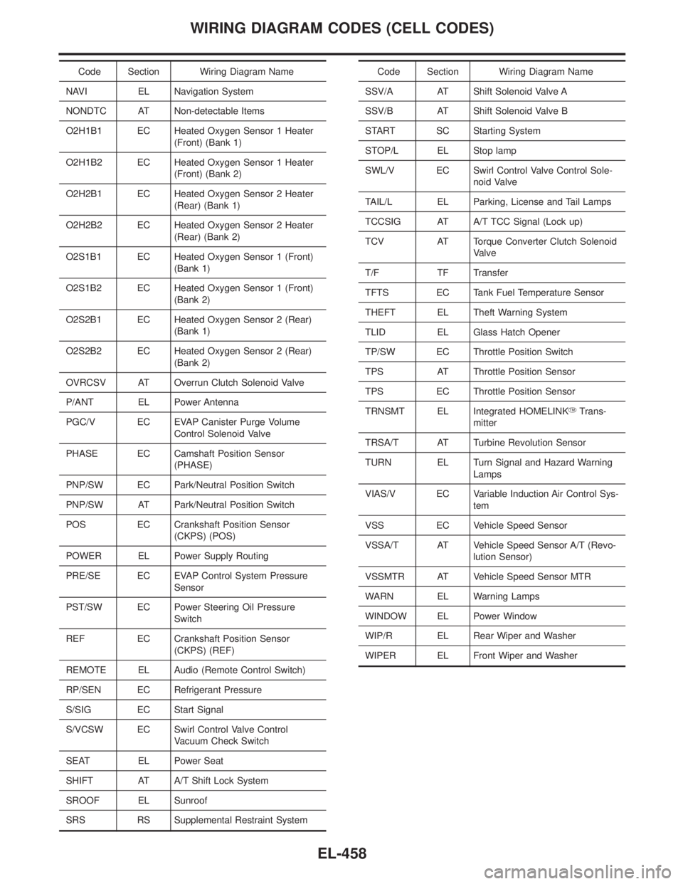
Code Section Wiring Diagram Name
NAVI EL Navigation System
NONDTC AT Non-detectable Items
O2H1B1 EC Heated Oxygen Sensor 1 Heater
(Front) (Bank 1)
O2H1B2 EC Heated Oxygen Sensor 1 Heater
(Front) (Bank 2)
O2H2B1 EC Heated Oxygen Sensor 2 Heater
(Rear) (Bank 1)
O2H2B2 EC Heated Oxygen Sensor 2 Heater
(Rear) (Bank 2)
O2S1B1 EC Heated Oxygen Sensor 1 (Front)
(Bank 1)
O2S1B2 EC Heated Oxygen Sensor 1 (Front)
(Bank 2)
O2S2B1 EC Heated Oxygen Sensor 2 (Rear)
(Bank 1)
O2S2B2 EC Heated Oxygen Sensor 2 (Rear)
(Bank 2)
OVRCSV AT Overrun Clutch Solenoid Valve
P/ANT EL Power Antenna
PGC/V EC EVAP Canister Purge Volume
Control Solenoid Valve
PHASE EC Camshaft Position Sensor
(PHASE)
PNP/SW EC Park/Neutral Position Switch
PNP/SW AT Park/Neutral Position Switch
POS EC Crankshaft Position Sensor
(CKPS) (POS)
POWER EL Power Supply Routing
PRE/SE EC EVAP Control System Pressure
Sensor
PST/SW EC Power Steering Oil Pressure
Switch
REF EC Crankshaft Position Sensor
(CKPS) (REF)
REMOTE EL Audio (Remote Control Switch)
RP/SEN EC Refrigerant Pressure
S/SIG EC Start Signal
S/VCSW EC Swirl Control Valve Control
Vacuum Check Switch
SEAT EL Power Seat
SHIFT AT A/T Shift Lock System
SROOF EL Sunroof
SRS RS Supplemental Restraint SystemCode Section Wiring Diagram Name
SSV/A AT Shift Solenoid Valve A
SSV/B AT Shift Solenoid Valve B
START SC Starting System
STOP/L EL Stop lamp
SWL/V EC Swirl Control Valve Control Sole-
noid Valve
TAIL/L EL Parking, License and Tail Lamps
TCCSIG AT A/T TCC Signal (Lock up)
TCV AT Torque Converter Clutch Solenoid
Valve
T/F TF Transfer
TFTS EC Tank Fuel Temperature Sensor
THEFT EL Theft Warning System
TLID EL Glass Hatch Opener
TP/SW EC Throttle Position Switch
TPS AT Throttle Position Sensor
TPS EC Throttle Position Sensor
TRNSMT EL Integrated HOMELINKYTrans-
mitter
TRSA/T AT Turbine Revolution Sensor
TURN EL Turn Signal and Hazard Warning
Lamps
VIAS/V EC Variable Induction Air Control Sys-
tem
VSS EC Vehicle Speed Sensor
VSSA/T AT Vehicle Speed Sensor A/T (Revo-
lution Sensor)
VSSMTR AT Vehicle Speed Sensor MTR
WARN EL Warning Lamps
WINDOW EL Power Window
WIP/R EL Rear Wiper and Washer
WIPER EL Front Wiper and Washer
WIRING DIAGRAM CODES (CELL CODES)
EL-458
Page 1658 of 2395
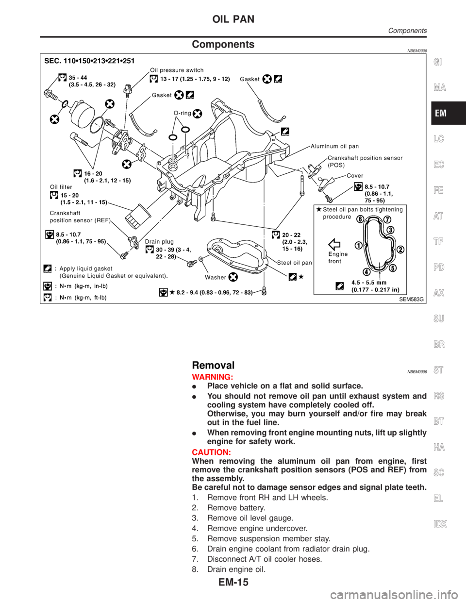
ComponentsNBEM0008
SEM583G
RemovalNBEM0009WARNING:
IPlace vehicle on a flat and solid surface.
IYou should not remove oil pan until exhaust system and
cooling system have completely cooled off.
Otherwise, you may burn yourself and/or fire may break
out in the fuel line.
IWhen removing front engine mounting nuts, lift up slightly
engine for safety work.
CAUTION:
When removing the aluminum oil pan from engine, first
remove the crankshaft position sensors (POS and REF) from
the assembly.
Be careful not to damage sensor edges and signal plate teeth.
1. Remove front RH and LH wheels.
2. Remove battery.
3. Remove oil level gauge.
4. Remove engine undercover.
5. Remove suspension member stay.
6. Drain engine coolant from radiator drain plug.
7. Disconnect A/T oil cooler hoses.
8. Drain engine oil.
GI
MA
LC
EC
FE
AT
TF
PD
AX
SU
BR
ST
RS
BT
HA
SC
EL
IDX
OIL PAN
Components
EM-15
Page 1659 of 2395
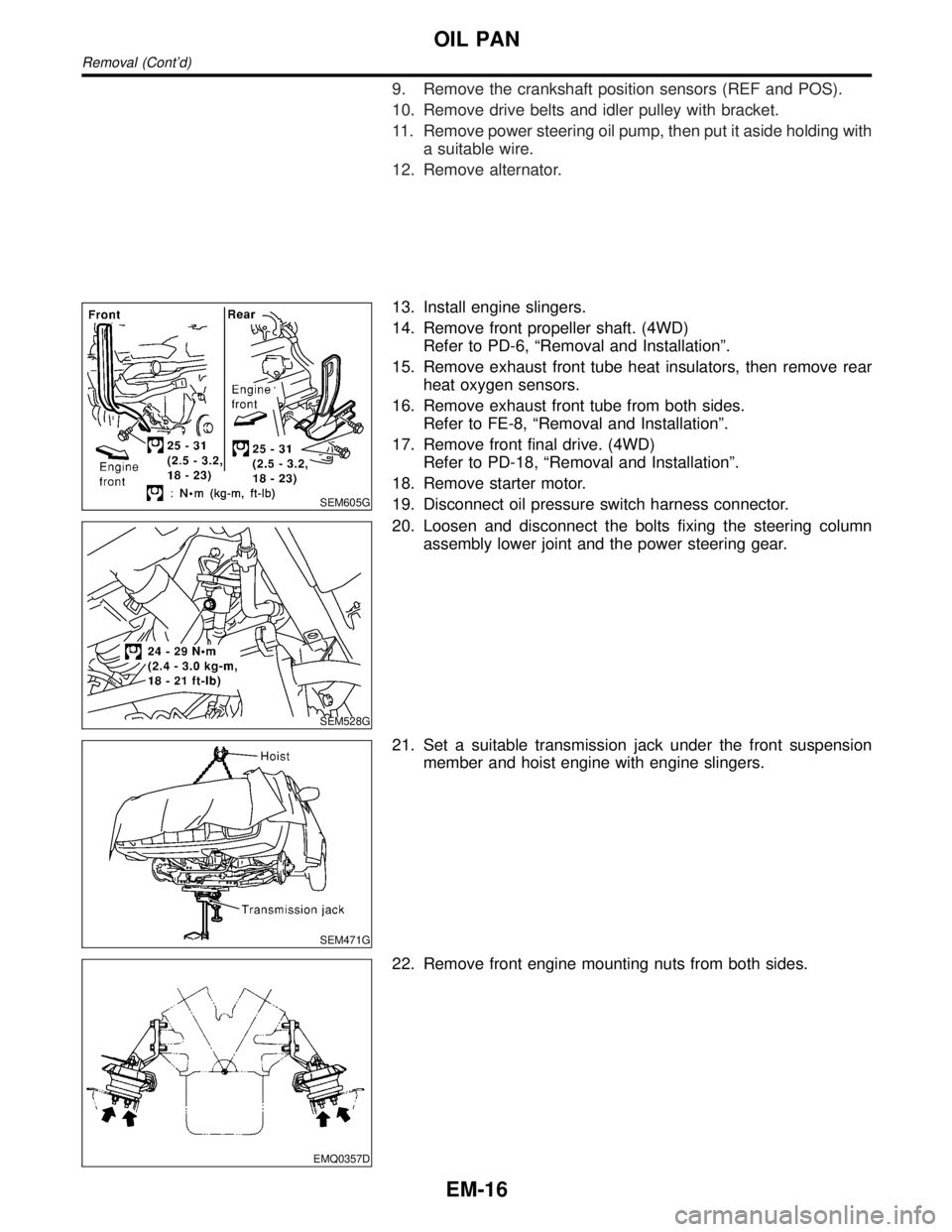
9. Remove the crankshaft position sensors (REF and POS).
10. Remove drive belts and idler pulley with bracket.
11. Remove power steering oil pump, then put it aside holding with
a suitable wire.
12. Remove alternator.
SEM605G
13. Install engine slingers.
14. Remove front propeller shaft. (4WD)
Refer to PD-6, ªRemoval and Installationº.
15. Remove exhaust front tube heat insulators, then remove rear
heat oxygen sensors.
16. Remove exhaust front tube from both sides.
Refer to FE-8, ªRemoval and Installationº.
17. Remove front final drive. (4WD)
Refer to PD-18, ªRemoval and Installationº.
18. Remove starter motor.
19. Disconnect oil pressure switch harness connector.
SEM528G
20. Loosen and disconnect the bolts fixing the steering column
assembly lower joint and the power steering gear.
SEM471G
21. Set a suitable transmission jack under the front suspension
member and hoist engine with engine slingers.
EMQ0357D
22. Remove front engine mounting nuts from both sides.
OIL PAN
Removal (Cont'd)
EM-16
Page 1667 of 2395

SEM421G
SEM422G
13. Remove camshaft position sensor (PHASE), CVTC sensors
and crankshaft position sensor (REF).
IAvoid impact such as dropping.
IDo not disassemble the components.
IDo not place them on areas where iron powder may adhere.
IKeep away from the objects susceptible to magnetism.
SEM412G
14. Remove upper intake manifold collector in reverse order of
installation. Refer to EM-12, ªUpper Intake Manifold Collectorº.
SEM413G
15. Remove intake manifold collector support bolts.
SEM414G
16. Remove lower intake manifold collector in reverse order of
installation. Refer to EM-13, ªLower Intake Manifold Collectorº.
TIMING CHAIN
Removal (Cont'd)
EM-24
Page 1676 of 2395

SEM439G
SEM440G
17. Install RH and LH rocker covers.
Rocker cover tightening procedure:
ITighten in numerical order as shown in the figure.
a. Tighten bolts 1 to 10 in that order to 6.9 to 8.8 N´m (0.7 to 0.9
kg-m, 61 to 78 in-lb).
b. Then tighten bolts 1 to 10 as indicated in figure to 6.9 to 8.8
N´m (0.7 to 0.9 kg-m, 61 to 78 in-lb).
18. Hang engine using the right and left side engine slingers with
a suitable hoist.
19. Set a suitable transmission jack under the suspension mem-
ber.
20. Remove right and left side engine mounting nuts.
21. Remove right and left side suspension member bolts.
22. Install aluminum oil pan. Refer to EM-18, ªInstallationº.
23. Set ring gear stopper using the mounting bolt hole.
IBe careful not to damage the signal plate teeth.
SEM417G
24. Install crankshaft pulley to crankshaft.
IAlign pointer with TDC mark on crankshaft pulley.
SEM531G
25. Install crankshaft pulley bolt.
ILubricate thread and seat surface of the bolt with new
engine oil.
a. Tighten to 39 to 49 N´m (4.0 to 5.0 kg-m, 29 to 36 ft-lb).
b. Put a paint mark on the crankshaft pulley.
SEM963E
c. Again tighten by turning 60É to 66É, about the angle from one
hexagon bolt head corner to another.
26. Install camshaft position sensor (PHASE), crankshaft position
sensors (REF)/(POS) and CVTC sensors.
27. Reinstall removed parts in the reverse order of removal.
IWhen installing fuel tube and intake manifold collectors, refer
to EM-12, ªTIGHTENING PROCEDURESº.
IAfter starting engine, keep idling for three minutes. Then
rev engine up to 3,000 rpm under no load to purge air from
the high-pressure chamber of the chain tensioners. The
engine may produce a rattling noise. This indicates that
GI
MA
LC
EC
FE
AT
TF
PD
AX
SU
BR
ST
RS
BT
HA
SC
EL
IDX
TIMING CHAIN
Installation (Cont'd)
EM-33
Page 1678 of 2395
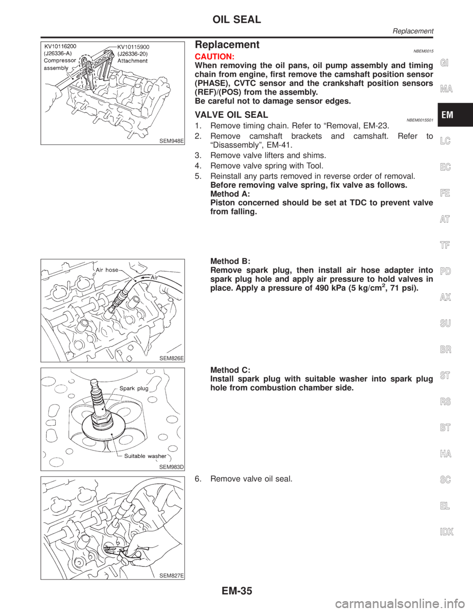
SEM948E
ReplacementNBEM0015CAUTION:
When removing the oil pans, oil pump assembly and timing
chain from engine, first remove the camshaft position sensor
(PHASE), CVTC sensor and the crankshaft position sensors
(REF)/(POS) from the assembly.
Be careful not to damage sensor edges.
VALVE OIL SEALNBEM0015S011. Remove timing chain. Refer to ªRemoval, EM-23.
2. Remove camshaft brackets and camshaft. Refer to
ªDisassemblyº, EM-41.
3. Remove valve lifters and shims.
4. Remove valve spring with Tool.
5. Reinstall any parts removed in reverse order of removal.
Before removing valve spring, fix valve as follows.
Method A:
Piston concerned should be set at TDC to prevent valve
from falling.
SEM826E
Method B:
Remove spark plug, then install air hose adapter into
spark plug hole and apply air pressure to hold valves in
place. Apply a pressure of 490 kPa (5 kg/cm
2, 71 psi).
SEM983D
Method C:
Install spark plug with suitable washer into spark plug
hole from combustion chamber side.
SEM827E
6. Remove valve oil seal.
GI
MA
LC
EC
FE
AT
TF
PD
AX
SU
BR
ST
RS
BT
HA
SC
EL
IDX
OIL SEAL
Replacement
EM-35
Page 1679 of 2395

SEM828E
7. Apply engine oil to new valve oil seal and install it with Tool.
SEM715A
OIL SEAL INSTALLATION DIRECTIONNBEM0015S02IInstall new oil seal in the direction shown in the figure.
FRONT OIL SEALNBEM0015S031. Remove the following parts:
IEngine undercover
ISuspension member stay
IDrive belts
ICrankshaft position sensor (REF)
Be careful not to damage sensor edge.
ICrankshaft pulley
IRadiator
ICooling fan
SEM829E
2. Remove front oil seal using a suitable tool.
Be careful not to scratch front cover.
3. Apply engine oil to new oil seal and install it using a suitable
tool.
SEM830E
REAR OIL SEALNBEM0015S041. Remove transmission. Refer to AT-277, ªRemovalº.
2. Remove drive plate.
3. Remove oil pan. Refer to EM-15.
4. Remove rear oil seal retainer.
OIL SEAL
Replacement (Cont'd)
EM-36
Page 1700 of 2395
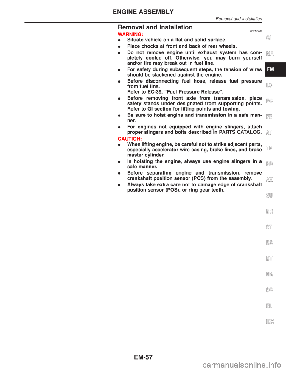
Removal and InstallationNBEM0042WARNING:
ISituate vehicle on a flat and solid surface.
IPlace chocks at front and back of rear wheels.
IDo not remove engine until exhaust system has com-
pletely cooled off. Otherwise, you may burn yourself
and/or fire may break out in fuel line.
IFor safety during subsequent steps, the tension of wires
should be slackened against the engine.
IBefore disconnecting fuel hose, release fuel pressure
from fuel line.
Refer to EC-39, ªFuel Pressure Releaseº.
IBefore removing front axle from transmission, place
safety stands under designated front supporting points.
Refer to GI section for lifting points and towing.
IBe sure to hoist engine and transmission in a safe man-
ner.
IFor engines not equipped with engine slingers, attach
proper slingers and bolts described in PARTS CATALOG.
CAUTION:
IWhen lifting engine, be careful not to strike adjacent parts,
especially accelerator wire casing, brake lines, and brake
master cylinder.
IIn hoisting the engine, always use engine slingers in a
safe manner.
IBefore separating engine and transmission, remove
crankshaft position sensor (POS) from the assembly.
IAlways take extra care not to damage edge of crankshaft
position sensor (POS), or ring gear teeth.GI
MA
LC
EC
FE
AT
TF
PD
AX
SU
BR
ST
RS
BT
HA
SC
EL
IDX
ENGINE ASSEMBLY
Removal and Installation
EM-57
Page 1796 of 2395
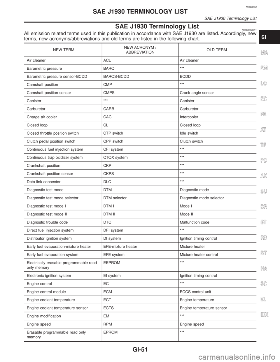
NBGI0010
SAE J1930 Terminology ListNBGI0010S01All emission related terms used in this publication in accordance with SAE J1930 are listed. Accordingly, new
terms, new acronyms/abbreviations and old terms are listed in the following chart.
NEW TERMNEW ACRONYM /
ABBREVIATIONOLD TERM
Air cleaner ACL Air cleaner
Barometric pressure BARO ***
Barometric pressure sensor-BCDD BAROS-BCDD BCDD
Camshaft position CMP ***
Camshaft position sensor CMPS Crank angle sensor
Canister *** Canister
Carburetor CARB Carburetor
Charge air cooler CAC Intercooler
Closed loop CL Closed loop
Closed throttle position switch CTP switch Idle switch
Clutch pedal position switch CPP switch Clutch switch
Continuous fuel injection system CFI system ***
Continuous trap oxidizer system CTOX system ***
Crankshaft position CKP ***
Crankshaft position sensor CKPS ***
Data link connector DLC ***
Diagnostic test mode DTM Diagnostic mode
Diagnostic test mode selector DTM selector Diagnostic mode selector
Diagnostic test mode I DTM I Mode I
Diagnostic test mode II DTM II Mode II
Diagnostic trouble code DTC Malfunction code
Direct fuel injection system DFI system ***
Distributor ignition system DI system Ignition timing control
Early fuel evaporation-mixture heater EFE-mixture heater Mixture heater
Early fuel evaporation system EFE system Mixture heater control
Electrically erasable programmable read
only memoryEEPROM ***
Electronic ignition system EI system Ignition timing control
Engine control EC ***
Engine control module ECM ECCS control unit
Engine coolant temperature ECT Engine temperature
Engine coolant temperature sensor ECTS Engine temperature sensor
Engine modification EM ***
Engine speed RPM Engine speed
Erasable programmable read only
memoryEPROM ***MA
EM
LC
EC
FE
AT
TF
PD
AX
SU
BR
ST
RS
BT
HA
SC
EL
IDX
SAE J1930 TERMINOLOGY LIST
SAE J1930 Terminology List
GI-51