height INFINITI QX4 2001 Factory Manual PDF
[x] Cancel search | Manufacturer: INFINITI, Model Year: 2001, Model line: QX4, Model: INFINITI QX4 2001Pages: 2395, PDF Size: 43.2 MB
Page 2065 of 2395
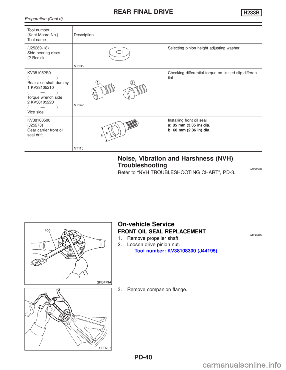
Tool number
(Kent-Moore No.)
Tool nameDescription
(J25269-18)
Side bearing discs
(2 Req'd)
NT135
Selecting pinion height adjusting washer
KV381052S0
(Ð)
Rear axle shaft dummy
1 KV38105210
(Ð)
Torque wrench side
2 KV38105220
(Ð)
Vice side
NT142
Checking differential torque on limited slip differen-
tial
KV38100500
(J25273)
Gear carrier front oil
seal drift
NT115
Installing front oil seal
a: 85 mm (3.35 in) dia.
b: 60 mm (2.36 in) dia.
Noise, Vibration and Harshness (NVH)
Troubleshooting
NBPD0051Refer to ªNVH TROUBLESHOOTING CHARTº, PD-3.
SPD479A
On-vehicle Service
FRONT OIL SEAL REPLACEMENTNBPD00301. Remove propeller shaft.
2. Loosen drive pinion nut.
Tool number: KV38108300 (J44195)
SPD737
3. Remove companion flange.
REAR FINAL DRIVEH233B
Preparation (Cont'd)
PD-40
Page 2078 of 2395
SPD364A
9. Tighten differential case couple bolts.
10. Place ring gear on differential case and tighten ring gear bolts.
Tighten bolts in a criss-cross pattern, lightly tapping bolt head
with a hammer.
Then bend up lock straps to lock the bolts in place.
11. Install side bearing inner cone.
12. Check differential torque.
AdjustmentNBPD0040For quiet and reliable final drive operation, the following five adjust-
ments must be made correctly:
1. Side bearing preload
2. Pinion gear height
3. Side bearing preload
4. Ring gear-to-pinion backlash. Refer to SDS, PD-62.
5. Ring and pinion gear tooth contact pattern
SPD196A
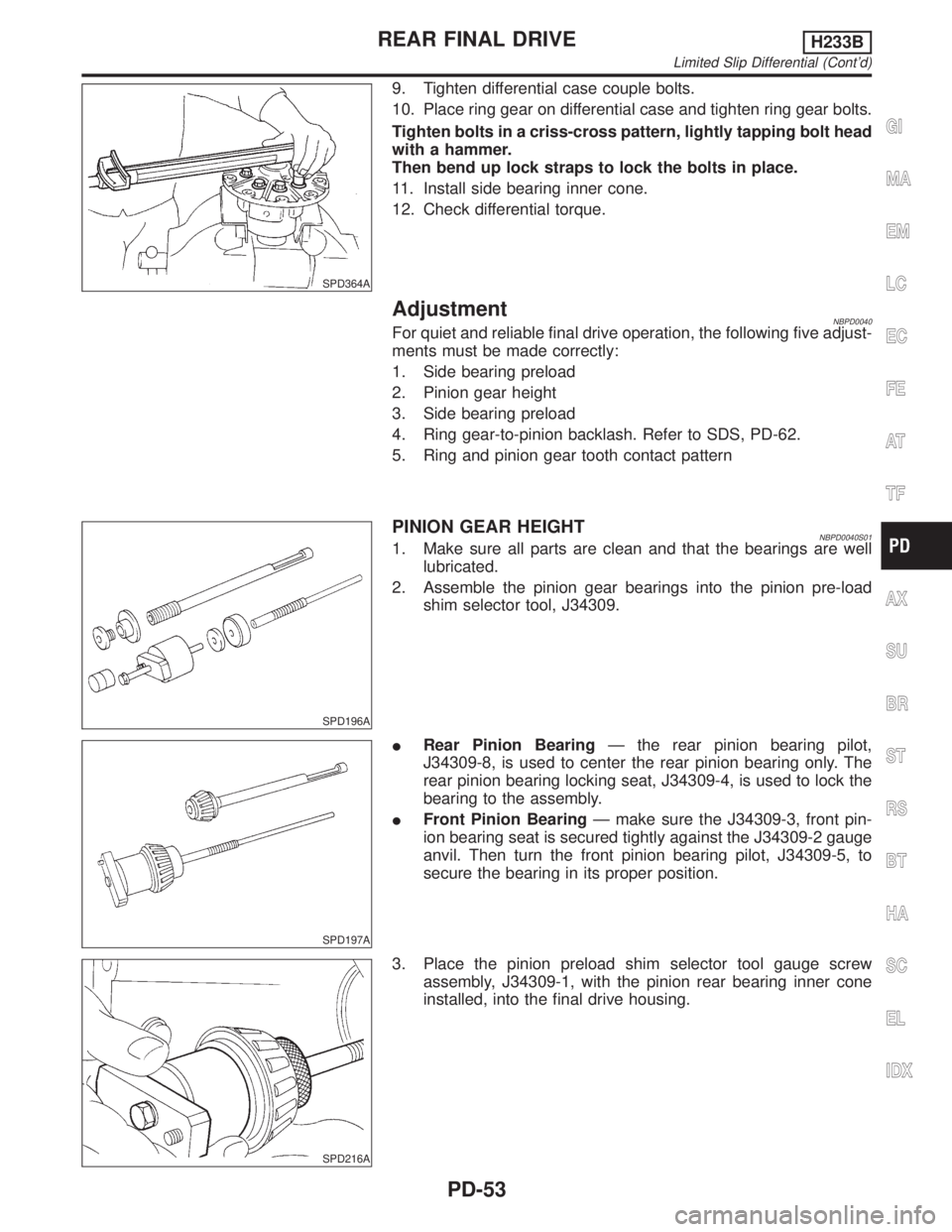
PINION GEAR HEIGHTNBPD0040S011. Make sure all parts are clean and that the bearings are well
lubricated.
2. Assemble the pinion gear bearings into the pinion pre-load
shim selector tool, J34309.
SPD197A
IRear Pinion BearingÐ the rear pinion bearing pilot,
J34309-8, is used to center the rear pinion bearing only. The
rear pinion bearing locking seat, J34309-4, is used to lock the
bearing to the assembly.
IFront Pinion BearingÐ make sure the J34309-3, front pin-
ion bearing seat is secured tightly against the J34309-2 gauge
anvil. Then turn the front pinion bearing pilot, J34309-5, to
secure the bearing in its proper position.
SPD216A
3. Place the pinion preload shim selector tool gauge screw
assembly, J34309-1, with the pinion rear bearing inner cone
installed, into the final drive housing.
GI
MA
EM
LC
EC
FE
AT
TF
AX
SU
BR
ST
RS
BT
HA
SC
EL
IDX
REAR FINAL DRIVEH233B
Limited Slip Differential (Cont'd)
PD-53
Page 2079 of 2395
SPD217A
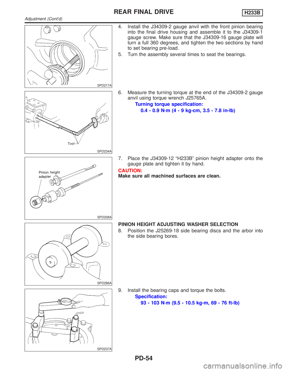
4. Install the J34309-2 gauge anvil with the front pinion bearing
into the final drive housing and assemble it to the J34309-1
gauge screw. Make sure that the J34309-16 gauge plate will
turn a full 360 degrees, and tighten the two sections by hand
to set bearing pre-load.
5. Turn the assembly several times to seat the bearings.
SPD234A
6. Measure the turning torque at the end of the J34309-2 gauge
anvil using torque wrench J25765A.
Turning torque specification:
0.4 - 0.9 N´m (4 - 9 kg-cm, 3.5 - 7.8 in-lb)
SPD208A
7. Place the J34309-12 ªH233Bº pinion height adapter onto the
gauge plate and tighten it by hand.
CAUTION:
Make sure all machined surfaces are clean.
SPD286A
PINION HEIGHT ADJUSTING WASHER SELECTION
8. Position the J25269-18 side bearing discs and the arbor into
the side bearing bores.
SPD237A
9. Install the bearing caps and torque the bolts.
Specification:
93 - 103 N´m (9.5 - 10.5 kg-m, 69 - 76 ft-lb)
REAR FINAL DRIVEH233B
Adjustment (Cont'd)
PD-54
Page 2080 of 2395
SPD204A
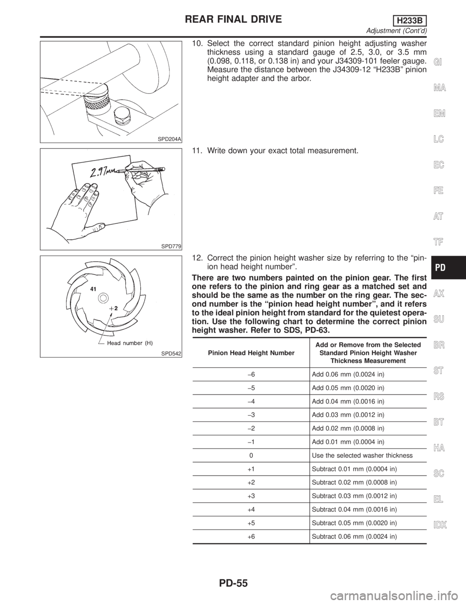
10. Select the correct standard pinion height adjusting washer
thickness using a standard gauge of 2.5, 3.0, or 3.5 mm
(0.098, 0.118, or 0.138 in) and your J34309-101 feeler gauge.
Measure the distance between the J34309-12 ªH233Bº pinion
height adapter and the arbor.
SPD779
11. Write down your exact total measurement.
SPD542
12. Correct the pinion height washer size by referring to the ªpin-
ion head height numberº.
There are two numbers painted on the pinion gear. The first
one refers to the pinion and ring gear as a matched set and
should be the same as the number on the ring gear. The sec-
ond number is the ªpinion head height numberº, and it refers
to the ideal pinion height from standard for the quietest opera-
tion. Use the following chart to determine the correct pinion
height washer. Refer to SDS, PD-63.
Pinion Head Height NumberAdd or Remove from the Selected
Standard Pinion Height Washer
Thickness Measurement
þ6 Add 0.06 mm (0.0024 in)
þ5 Add 0.05 mm (0.0020 in)
þ4 Add 0.04 mm (0.0016 in)
þ3 Add 0.03 mm (0.0012 in)
þ2 Add 0.02 mm (0.0008 in)
þ1 Add 0.01 mm (0.0004 in)
0 Use the selected washer thickness
+1 Subtract 0.01 mm (0.0004 in)
+2 Subtract 0.02 mm (0.0008 in)
+3 Subtract 0.03 mm (0.0012 in)
+4 Subtract 0.04 mm (0.0016 in)
+5 Subtract 0.05 mm (0.0020 in)
+6 Subtract 0.06 mm (0.0024 in)
GI
MA
EM
LC
EC
FE
AT
TF
AX
SU
BR
ST
RS
BT
HA
SC
EL
IDX
REAR FINAL DRIVEH233B
Adjustment (Cont'd)
PD-55
Page 2083 of 2395
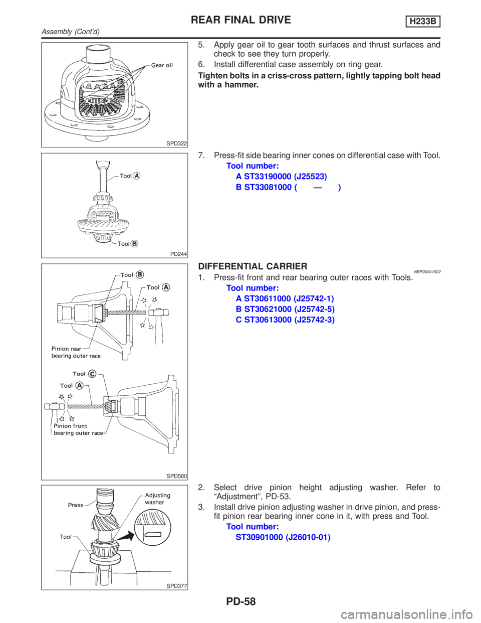
SPD322
5. Apply gear oil to gear tooth surfaces and thrust surfaces and
check to see they turn properly.
6. Install differential case assembly on ring gear.
Tighten bolts in a criss-cross pattern, lightly tapping bolt head
with a hammer.
PD244
7. Press-fit side bearing inner cones on differential case with Tool.
Tool number:
A ST33190000 (J25523)
B ST33081000 ( Ð )
SPD580
DIFFERENTIAL CARRIERNBPD0041S021. Press-fit front and rear bearing outer races with Tools.
Tool number:
A ST30611000 (J25742-1)
B ST30621000 (J25742-5)
C ST30613000 (J25742-3)
SPD377
2. Select drive pinion height adjusting washer. Refer to
ªAdjustmentº, PD-53.
3. Install drive pinion adjusting washer in drive pinion, and press-
fit pinion rear bearing inner cone in it, with press and Tool.
Tool number:
ST30901000 (J26010-01)
REAR FINAL DRIVEH233B
Assembly (Cont'd)
PD-58
Page 2088 of 2395
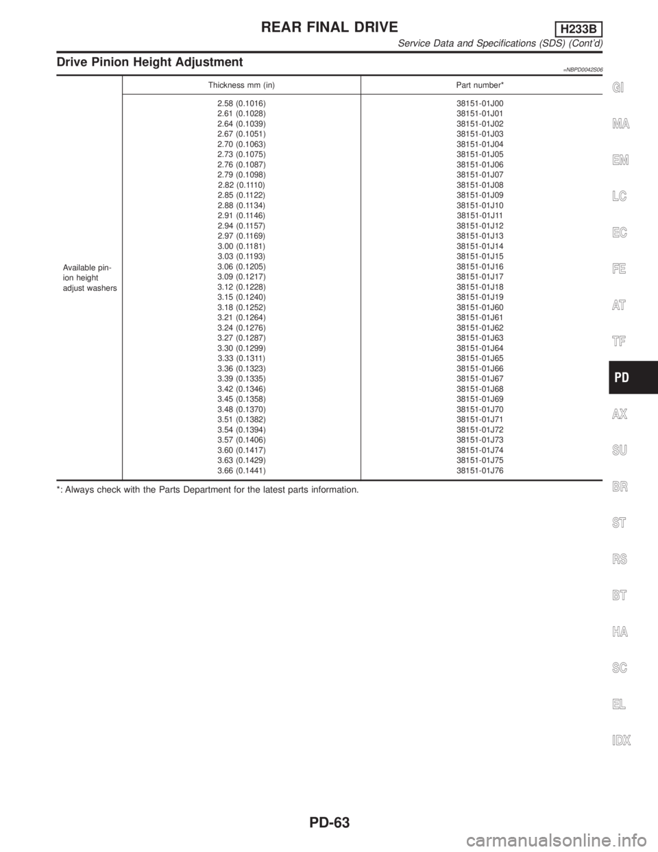
Drive Pinion Height Adjustment=NBPD0042S06
Available pin-
ion height
adjust washersThickness mm (in) Part number*
2.58 (0.1016)
2.61 (0.1028)
2.64 (0.1039)
2.67 (0.1051)
2.70 (0.1063)
2.73 (0.1075)
2.76 (0.1087)
2.79 (0.1098)
2.82 (0.1110)
2.85 (0.1122)
2.88 (0.1134)
2.91 (0.1146)
2.94 (0.1157)
2.97 (0.1169)
3.00 (0.1181)
3.03 (0.1193)
3.06 (0.1205)
3.09 (0.1217)
3.12 (0.1228)
3.15 (0.1240)
3.18 (0.1252)
3.21 (0.1264)
3.24 (0.1276)
3.27 (0.1287)
3.30 (0.1299)
3.33 (0.1311)
3.36 (0.1323)
3.39 (0.1335)
3.42 (0.1346)
3.45 (0.1358)
3.48 (0.1370)
3.51 (0.1382)
3.54 (0.1394)
3.57 (0.1406)
3.60 (0.1417)
3.63 (0.1429)
3.66 (0.1441)38151-01J00
38151-01J01
38151-01J02
38151-01J03
38151-01J04
38151-01J05
38151-01J06
38151-01J07
38151-01J08
38151-01J09
38151-01J10
38151-01J11
38151-01J12
38151-01J13
38151-01J14
38151-01J15
38151-01J16
38151-01J17
38151-01J18
38151-01J19
38151-01J60
38151-01J61
38151-01J62
38151-01J63
38151-01J64
38151-01J65
38151-01J66
38151-01J67
38151-01J68
38151-01J69
38151-01J70
38151-01J71
38151-01J72
38151-01J73
38151-01J74
38151-01J75
38151-01J76
*: Always check with the Parts Department for the latest parts information.
GI
MA
EM
LC
EC
FE
AT
TF
AX
SU
BR
ST
RS
BT
HA
SC
EL
IDX
REAR FINAL DRIVEH233B
Service Data and Specifications (SDS) (Cont'd)
PD-63
Page 2096 of 2395
Seat Belt Inspection=NBRS0029AFTER A COLLISIONNBRS0029S01WARNING:
Inspect all seat belt assemblies including retractors and attaching hardware after any collision.
NISSAN recommends that all seat belt assemblies in use during a collision be replaced unless the
collision was minor and the belts show no damage and continue to operate properly. Failure to do so
could result in serious personal injury in an accident. Seat belt assemblies not in use during a colli-
sion should also be replaced if either damage or improper operation is noted. Seat belt pre-tensioner
should be replaced even if the seat belts are not in use during a frontal collision in which the air bags
are deployed.
Replace any seat belt assembly if:
IThe seat belt was in use at the time of a collision (except for minor collisions and the belts, retractors and
buckles show no damage and continue to operate properly).
IThe seat belt was damaged in an accident. (i.e. torn webbing, bent retractor or guide, etc.)
IThe seat belt attaching point was damaged in an accident. Inspect the seat belt attaching area for dam-
age or distortion and repair as necessary before installing a new seat belt assembly.
IAnchor bolts are deformed or worn out.
IThe seat belt pre-tensioner should be replaced even if the seat belts are not in use during the collision in
which the air bags are deployed.
PRELIMINARY CHECKSNBRS0029S021. Check the seat belt warning lamp/chime for proper operation as follows:
a. Switch ignition ON. The seat belt warning lamp should illuminate. Also, the seat belt warning chime should
sound for about seven seconds.
b. Fasten driver's seat belt. The seat belt warning lamp should go out and the chime (if sounding) should
stop.
2. If the air bag warning lamp is blinking, conduct self-diagnosis using CONSULT-II, and air bag warning lamp.
Refer to ªSRS Operation Checkº, RS-38.
3. Check that the seat belt retractor, seat belt anchor and buckle bolts are securely attached.
4. Check the shoulder seat belt guide and shoulder belt height adjuster for front seats. Ensure guide swiv-
els freely and that belt lays flat and does not bind in guide. Ensure height adjuster operates properly and
holds securely.
5. Check retractor operation:
a. Fully extend the seat belt webbing and check for twists, tears or other damage.
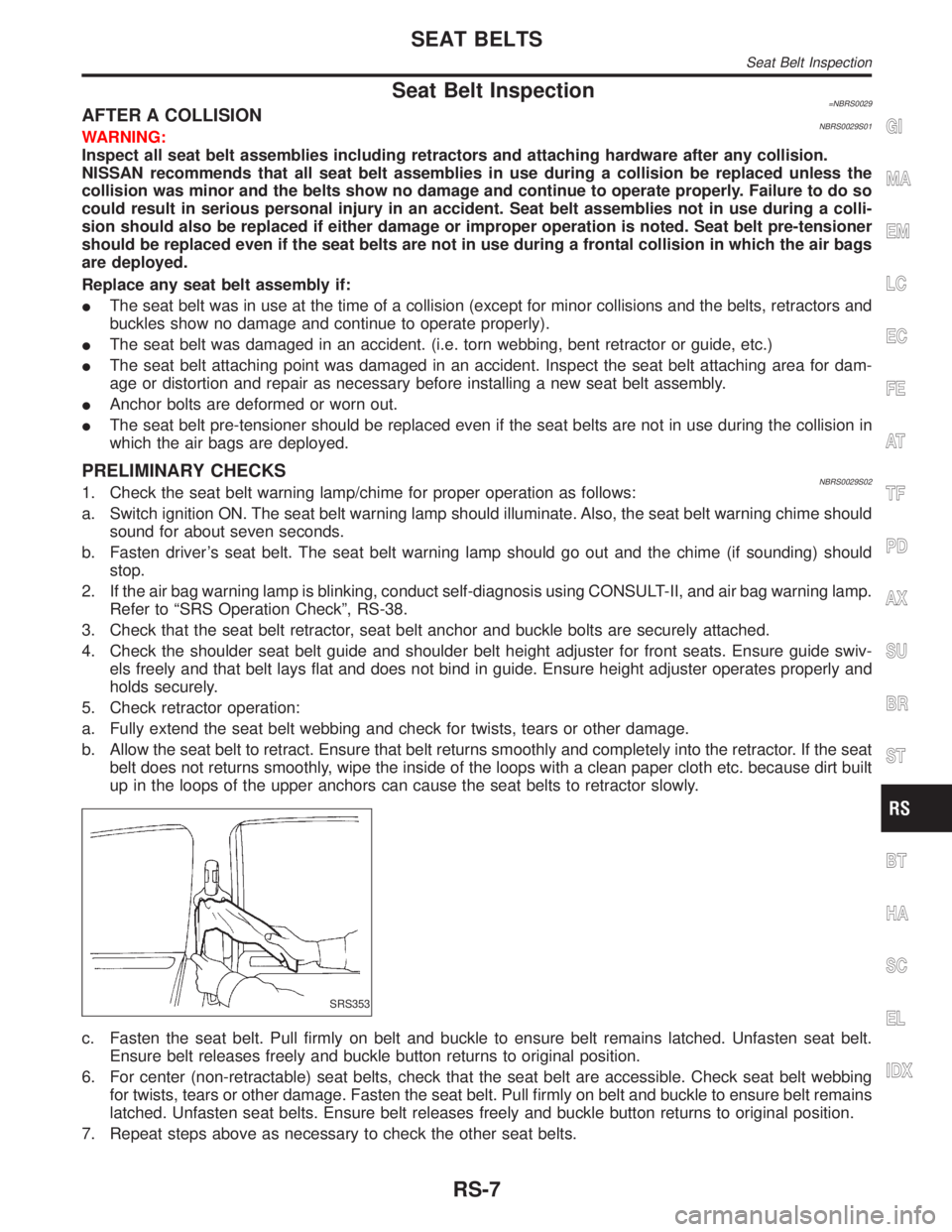
b. Allow the seat belt to retract. Ensure that belt returns smoothly and completely into the retractor. If the seat
belt does not returns smoothly, wipe the inside of the loops with a clean paper cloth etc. because dirt built
up in the loops of the upper anchors can cause the seat belts to retractor slowly.
SRS353
c. Fasten the seat belt. Pull firmly on belt and buckle to ensure belt remains latched. Unfasten seat belt.
Ensure belt releases freely and buckle button returns to original position.
6. For center (non-retractable) seat belts, check that the seat belt are accessible. Check seat belt webbing
for twists, tears or other damage. Fasten the seat belt. Pull firmly on belt and buckle to ensure belt remains
latched. Unfasten seat belts. Ensure belt releases freely and buckle button returns to original position.
7. Repeat steps above as necessary to check the other seat belts.
GI
MA
EM
LC
EC
FE
AT
TF
PD
AX
SU
BR
ST
BT
HA
SC
EL
IDX
SEAT BELTS
Seat Belt Inspection
RS-7
Page 2180 of 2395
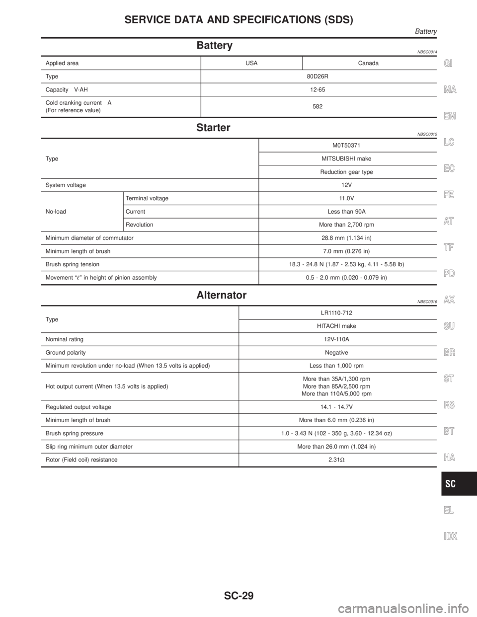
BatteryNBSC0014
Applied area USA Canada
Type80D26R
Capacity V-AH12-65
Cold cranking current A
(For reference value)582
StarterNBSC0015
TypeM0T50371
MITSUBISHI make
Reduction gear type
System voltage12V
No-loadTerminal voltage 11.0V
Current Less than 90A
Revolution More than 2,700 rpm
Minimum diameter of commutator28.8 mm (1.134 in)
Minimum length of brush7.0 mm (0.276 in)
Brush spring tension18.3 - 24.8 N (1.87 - 2.53 kg, 4.11 - 5.58 lb)
Movement ªº in height of pinion assembly 0.5 - 2.0 mm (0.020 - 0.079 in)
AlternatorNBSC0016
TypeLR1110-712
HITACHI make
Nominal rating12V-110A
Ground polarityNegative
Minimum revolution under no-load (When 13.5 volts is applied) Less than 1,000 rpm
Hot output current (When 13.5 volts is applied)More than 35A/1,300 rpm
More than 85A/2,500 rpm
More than 110A/5,000 rpm
Regulated output voltage14.1 - 14.7V
Minimum length of brushMore than 6.0 mm (0.236 in)
Brush spring pressure 1.0 - 3.43 N (102 - 350 g, 3.60 - 12.34 oz)
Slip ring minimum outer diameter More than 26.0 mm (1.024 in)
Rotor (Field coil) resistance2.31W
GI
MA
EM
LC
EC
FE
AT
TF
PD
AX
SU
BR
ST
RS
BT
HA
EL
IDX
SERVICE DATA AND SPECIFICATIONS (SDS)
Battery
SC-29
Page 2216 of 2395
FRONT & REAR SUSPENSION
SECTION
SU
CONTENTS
FRONT SUSPENSION....................................................2
Precautions ..................................................................2
PRECAUTIONS.........................................................2
Preparation ..................................................................2
SPECIAL SERVICE TOOLS........................................2
COMMERCIAL SERVICE TOOLS................................2
Noise, Vibration and Harshness (NVH)
Troubleshooting ...........................................................3
NVH TROUBLESHOOTING CHART............................3
Components.................................................................4
On-vehicle Service.......................................................5
FRONT SUSPENSION PARTS...................................5
FRONT WHEEL ALIGNMENT.....................................6
Coil Spring and Strut Assembly...................................8
COMPONENTS.........................................................8
REMOVAL.................................................................9
DISASSEMBLY..........................................................9
INSPECTION.............................................................9
ASSEMBLY.............................................................10
Stabilizer Bar .............................................................10
REMOVAL AND INSTALLATION...............................10
INSPECTION........................................................... 11
Transverse Link and Lower Ball Joint ....................... 11
REMOVAL AND INSTALLATION............................... 11
INSPECTION...........................................................12
Service Data and Specifications (SDS).....................13
GENERAL SPECIFICATIONS (FRONT).....................13
WHEEL ALIGNMENT (UNLADEN*1)..........................13
LOWER BALL JOINT...............................................13
WHEELARCH HEIGHT (UNLADEN*).........................14
WHEEL RUNOUT AVERAGE*..................................14
REAR SUSPENSION.....................................................15
Precautions ................................................................15
PRECAUTIONS.......................................................15
Preparation ................................................................15
COMMERCIAL SERVICE TOOLS..............................15
Noise, Vibration and Harshness (NVH)
Troubleshooting .........................................................15
Components...............................................................16
On-vehicle Service.....................................................16
REAR SUSPENSION PARTS...................................16
Removal and Installation ...........................................17
Coil Spring and Shock Absorber ...............................18
COMPONENTS.......................................................18
REMOVAL AND INSTALLATION...............................19
INSPECTION...........................................................19
Upper Link, Lower Link and Panhard Rod ................19
INSPECTION...........................................................19
BUSHING REPLACEMENT.......................................19
INSTALLATION........................................................20
Stabilizer Bar .............................................................20
REMOVAL AND INSTALLATION...............................20
Service Data and Specifications (SDS).....................20
GENERAL SPECIFICATIONS (REAR).......................20
GI
MA
EM
LC
EC
FE
AT
TF
PD
AX
BR
ST
RS
BT
HA
SC
EL
IDX
Page 2220 of 2395
SMA525A
On-vehicle Service
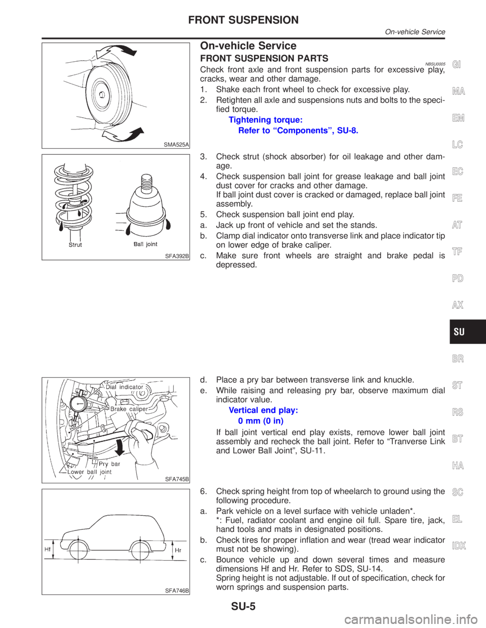
FRONT SUSPENSION PARTSNBSU0005Check front axle and front suspension parts for excessive play,
cracks, wear and other damage.
1. Shake each front wheel to check for excessive play.
2. Retighten all axle and suspensions nuts and bolts to the speci-
fied torque.
Tightening torque:
Refer to ªComponentsº, SU-8.
SFA392B
3. Check strut (shock absorber) for oil leakage and other dam-
age.
4. Check suspension ball joint for grease leakage and ball joint
dust cover for cracks and other damage.
If ball joint dust cover is cracked or damaged, replace ball joint
assembly.
5. Check suspension ball joint end play.
a. Jack up front of vehicle and set the stands.
b. Clamp dial indicator onto transverse link and place indicator tip
on lower edge of brake caliper.
c. Make sure front wheels are straight and brake pedal is
depressed.
SFA745B
d. Place a pry bar between transverse link and knuckle.
e. While raising and releasing pry bar, observe maximum dial
indicator value.
Vertical end play:
0mm(0in)
If ball joint vertical end play exists, remove lower ball joint
assembly and recheck the ball joint. Refer to ªTranverse Link
and Lower Ball Jointº, SU-11.
SFA746B
6. Check spring height from top of wheelarch to ground using the
following procedure.
a. Park vehicle on a level surface with vehicle unladen*.
*: Fuel, radiator coolant and engine oil full. Spare tire, jack,
hand tools and mats in designated positions.
b. Check tires for proper inflation and wear (tread wear indicator
must not be showing).
c. Bounce vehicle up and down several times and measure
dimensions Hf and Hr. Refer to SDS, SU-14.
Spring height is not adjustable. If out of specification, check for
worn springs and suspension parts.
GI
MA
EM
LC
EC
FE
AT
TF
PD
AX
BR
ST
RS
BT
HA
SC
EL
IDX
FRONT SUSPENSION
On-vehicle Service
SU-5