height INFINITI QX4 2001 Factory Workshop Manual
[x] Cancel search | Manufacturer: INFINITI, Model Year: 2001, Model line: QX4, Model: INFINITI QX4 2001Pages: 2395, PDF Size: 43.2 MB
Page 1574 of 2395
SEL690V
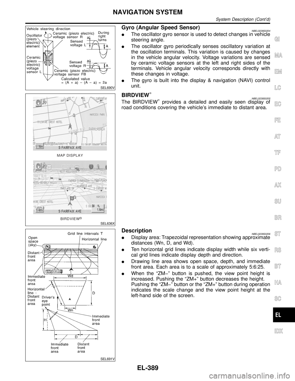
Gyro (Angular Speed Sensor)NBEL0228S0204IThe oscillator gyro sensor is used to detect changes in vehicle
steering angle.
IThe oscillator gyro periodically senses oscillatory variation at
the oscillation terminals. This variation is caused by changes
in the vehicle angular velocity. Voltage variations are sensed
by ceramic voltage sensors at the left and right sides of the
terminals. Vehicle angular velocity corresponds directly with
these changes in voltage.
IThe gyro is built into the display & navigation (NAVI) control
unit.
MAP DISPLAY
BIRDVIEW
R
SEL636X
BIRDVIEWTNBEL0228S0205The BIRDVIEWTprovides a detailed and easily seen display of
road conditions covering the vehicle's immediate to distant area.
SEL691V
DescriptionNBEL0228S0206IDisplay area: Trapezoidal representation showing approximate
distances (Wn, D, and Wd).
ITen horizontal grid lines indicate display width while six verti-
cal grid lines indicate display depth and direction.
IDrawing line area shows open space, depth, and immediate
front area. Each area is to a scale of approximately 5:6:25.
IWhen the ªZMþº button is pushed, the view point height is
increased. Pushing the ªZM+º button decreases the height.
Pushing the ªZMþº button or the ªZM+º button during operation
indicates the scale change and the view point height at the
left-hand side of the screen.
GI
MA
EM
LC
EC
FE
AT
TF
PD
AX
SU
BR
ST
RS
BT
HA
SC
IDX
NAVIGATION SYSTEM
System Description (Cont'd)
EL-389
Page 1644 of 2395
ENGINE MECHANICAL
SECTION
EM
CONTENTS
PRECAUTIONS...............................................................3
Parts Requiring Angular Tightening .............................3
Liquid Gasket Application Procedure ..........................3
PREPARATION...............................................................4
Special Service Tools ..................................................4
Commercial Service Tools ...........................................6
NOISE, VIBRATION AND HARSHNESS (NVH)
TROUBLESHOOTING.....................................................8
NVH Troubleshooting - Engine Noise .........................9
OUTER COMPONENT PARTS.....................................10
Removal and Installation ...........................................10
TIGHTENING PROCEDURES...................................12
MEASUREMENT OF COMPRESSION PRESSURE....14
OIL PAN.........................................................................15
Components...............................................................15
Removal .....................................................................15
Installation ..................................................................18
TIMING CHAIN..............................................................20
Components...............................................................20
POSITION FOR APPLYING LIQUID GASKET............21
Removal .....................................................................23
Inspection...................................................................29
Installation ..................................................................29
OIL SEAL.......................................................................35
Replacement ..............................................................35
VALVE OIL SEAL.....................................................35
OIL SEAL INSTALLATION DIRECTION.....................36
FRONT OIL SEAL....................................................36
REAR OIL SEAL......................................................36
CYLINDER HEAD..........................................................38
Components...............................................................38
Removal .....................................................................39
Disassembly...............................................................41
Inspection...................................................................42
CYLINDER HEAD DISTORTION...............................42
CAMSHAFT VISUAL CHECK....................................42
CAMSHAFT RUNOUT..............................................42
CAMSHAFT CAM HEIGHT.......................................42
CAMSHAFT JOURNAL CLEARANCE........................42
CAMSHAFT END PLAY............................................43
CAMSHAFT SPROCKET RUNOUT...........................43
VALVE GUIDE CLEARANCE....................................43
VALVE GUIDE REPLACEMENT................................44
VALVE SEATS.........................................................45
REPLACING VALVE SEAT FOR SERVICE PARTS....45
VALVE DIMENSIONS...............................................46
VALVE SPRING.......................................................46
VALVE LIFTER........................................................46
Assembly ...................................................................47
Installation ..................................................................47
Valve Clearance.........................................................52
CHECKING.............................................................52
ADJUSTING............................................................54
ENGINE ASSEMBLY.....................................................57
Removal and Installation ...........................................57
REMOVAL...............................................................58
INSTALLATION........................................................60
CYLINDER BLOCK.......................................................61
Components...............................................................61
CYLINDER BLOCK HEATER....................................62
Removal and Installation ...........................................62
Disassembly...............................................................62
PISTON, CRANKSHAFT AND OIL JET......................62
Inspection...................................................................63
PISTON AND PISTON PIN CLEARANCE..................63
PISTON RING SIDE CLEARANCE............................64
PISTON RING END GAP..........................................64
CONNECTING ROD BEND AND TORSION...............65
CYLINDER BLOCK DISTORTION AND WEAR...........65
PISTON-TO-BORE CLEARANCE..............................66
CRANKSHAFT.........................................................67
BEARING CLEARANCE...........................................67
CONNECTING ROD BUSHING CLEARANCE
(SMALL END)
..........................................................70
DRIVE PLATE RUNOUT..........................................70
Assembly ...................................................................71
PISTON..................................................................71
OIL JET..................................................................71
CRANKSHAFT.........................................................71
REPLACEMENT OF PILOT CONVERTER.................74
DRIVE PLATE.........................................................74
GI
MA
LC
EC
FE
AT
TF
PD
AX
SU
BR
ST
RS
BT
HA
SC
EL
IDX
Page 1685 of 2395

SEM861E
InspectionNBEM0019CYLINDER HEAD DISTORTIONNBEM0019S01Clean surface of cylinder head.
Use a reliable straightedge and feeler gauge to check the flatness
of cylinder head surface.
Check along six positions shown in the figure.
Head surface flatness: Limit 0.1 mm (0.004 in)
If beyond the specified limit, resurface or replace it.
The limit for cylinder head resurfacing is determined by the
cylinder block resurfacing.
Resurfacing limit:
Amount of cylinder head resurfacing is ªAº.
Amount of cylinder block resurfacing is ªBº.
The maximum limit : A+ B = 0.2 mm (0.008 in)
After resurfacing cylinder head, check that camshaft rotates freely
by hand. If resistance is felt, cylinder head must be replaced.
Nominal cylinder head height:
126.3 - 126.5 mm (4.972 - 4.980 in)
SEM191F
CAMSHAFT VISUAL CHECKNBEM0019S02Check camshaft for scratches, seizure and wear.
CAMSHAFT RUNOUTNBEM0019S031. Measure camshaft runout at A and B as shown in the figure.
Runout (Total indicator reading):
Limit 0.05 mm (0.0020 in)
2. If it exceeds the limit, replace camshaft.
SEM549A
CAMSHAFT CAM HEIGHTNBEM0019S041. Measure camshaft cam height.
Standard cam height:
Intake and exhaust
44.465 - 44.655 mm (1.7506 - 1.7581 in)
Cam wear limit:
0.2 mm (0.008 in)
2. If wear is beyond the limit, replace camshaft.
SEM862E
CAMSHAFT JOURNAL CLEARANCENBEM0019S051. Install camshaft bracket and tighten bolts to the specified
torque.
2. Measure inner diameter ªAº of camshaft bearing.
Standard inner diameter:
No. 1: 26.000 - 26.021 mm (1.0236 - 1.0244 in)
No. 2, 3, 4: 23.500 - 23.521 mm (0.9252 - 0.9260 in)
CYLINDER HEAD
Inspection
EM-42
Page 1689 of 2395

SEM188A
VALVE DIMENSIONSNBEM0019S12Check dimensions of each valve. For dimensions, refer to SDS
(EM-76).
When valve head has been worn down to 0.5 mm (0.020 in) in
margin thickness, replace valve.
Grinding allowance for valve stem tip is 0.2 mm (0.008 in) or
less.
SEM288A
VALVE SPRINGNBEM0019S13SquarenessNBEM0019S13011. Measure dimension ªSº.
Out-of-square ªSº:
Less than 2.0 mm (0.079 in)
2. If it exceeds the limit, replace spring.
EM113
PressureNBEM0019S1302Check valve spring pressure at specified spring height.
Pressure:
Standard
202 N (20.6 kg, 45.4 lb) at height 37.0 mm (1.457 in)
Limit
More than 436 N (44.5 kg, 98.1 lb) at height 28.2
mm (1.110 in)
If it exceeds the limit, replace spring.
SEM960E
VALVE LIFTERNBEM0019S141. Check contact and sliding surfaces for wear or scratches.
SEM961E
2. Check diameter of valve lifter and valve lifter guide bore.
Valve lifter outer diameter:
34.960 - 34.975 mm (1.3764 - 1.3770 in)
CYLINDER HEAD
Inspection (Cont'd)
EM-46
Page 1708 of 2395
SEM038F
SEM003F
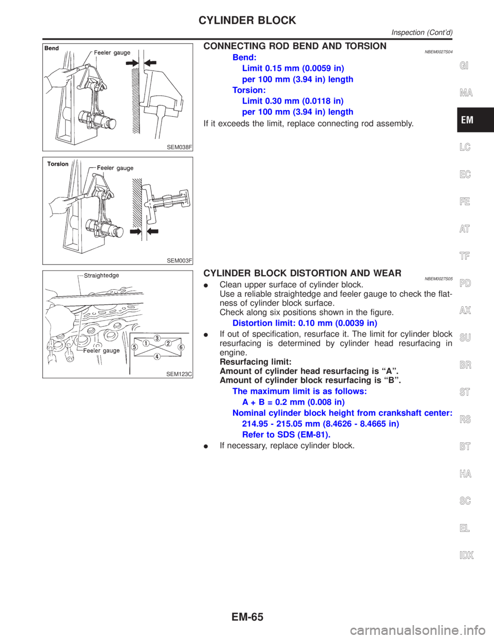
CONNECTING ROD BEND AND TORSIONNBEM0027S04Bend:
Limit 0.15 mm (0.0059 in)
per 100 mm (3.94 in) length
Torsion:
Limit 0.30 mm (0.0118 in)
per 100 mm (3.94 in) length
If it exceeds the limit, replace connecting rod assembly.
SEM123C
CYLINDER BLOCK DISTORTION AND WEARNBEM0027S05IClean upper surface of cylinder block.
Use a reliable straightedge and feeler gauge to check the flat-
ness of cylinder block surface.
Check along six positions shown in the figure.
Distortion limit: 0.10 mm (0.0039 in)
IIf out of specification, resurface it. The limit for cylinder block
resurfacing is determined by cylinder head resurfacing in
engine.
Resurfacing limit:
Amount of cylinder head resurfacing is ªAº.
Amount of cylinder block resurfacing is ªBº.
The maximum limit is as follows:
A + B = 0.2 mm (0.008 in)
Nominal cylinder block height from crankshaft center:
214.95 - 215.05 mm (8.4626 - 8.4665 in)
Refer to SDS (EM-81).
IIf necessary, replace cylinder block.
GI
MA
LC
EC
FE
AT
TF
PD
AX
SU
BR
ST
RS
BT
HA
SC
EL
IDX
CYLINDER BLOCK
Inspection (Cont'd)
EM-65
Page 1721 of 2395

Thickness mm (in) Identification mark
2.82 (0.1110) 282
2.83 (0.1114) 283
2.84 (0.1118) 284
2.85 (0.1122) 285
2.86 (0.1126) 286
2.87 (0.1130) 287
2.88 (0.1134) 288
2.89 (0.1138) 289
2.90 (0.1142) 290
2.91 (0.1146) 291
2.92 (0.1150) 292
2.93 (0.1154) 293
2.94 (0.1157) 294
2.95 (0.1161) 295
SEM966E
VALVE SPRINGNBEM0032S04
Free height mm (in)47.10 (1.8543)
Pressure N (kg, lb) at height mm (in)Standard 202 (20.6, 45.4) at 37.0 (1.457)
Limit 436 (44.5, 98.1) at 28.2 (1.110)
Out-of-square mm (in)Less than 2.0 (0.079)
VALVE LIFTERNBEM0032S05Unit: mm (in)
Valve lifter outer diameter 34.960 - 34.975 (1.3764 - 1.3770)
Lifter guide inner diameter 35.000 - 35.021 (1.3780 - 1.3788)
Clearance between lifter and lifter guide 0.025 - 0.061 (0.0010 - 0.0024)
SERVICE DATA AND SPECIFICATIONS (SDS)
Valve (Cont'd)
EM-78
Page 1723 of 2395

SEM621F
Standard Service
Cylinder head seat recess diameter (D)Intake 38.000 - 38.016 (1.4961 - 1.4967) 38.500 - 38.516 (1.5157 - 1.5164)
Exhaust 32.200 - 32.216 (1.2677 - 1.2683) 32.700 - 32.716 (1.2874 - 1.2880)
Valve seat interference fitIntake 0.081 - 0.113 (0.0032 - 0.0044)
Exhaust 0.064 - 0.096 (0.0025 - 0.0038)
Valve seat outer diameter (d)Intake 38.097 - 38.113 (1.4999 - 1.5005) 38.597 - 38.613 (1.5196 - 1.5202)
Exhaust 32.280 - 32.296 (1.2709 - 1.2715) 32.780 - 32.796 (1.2905 - 1.2912)
Height (h)Intake 5.9 - 6.0 (0.232 - 0.236) 5.05 - 5.15 (0.1988 - 0.2028)
Exhaust 5.9 - 6.0 (0.232 - 0.236) 4.95 - 5.05 (0.1949 - 0.1988)
Depth (H)5.9 - 6.1 (0.232 - 0.240)
Depth (L)Intake 41.07 - 41.67 (1.6169 - 1.6405)
Exhaust 41.00 - 41.60 (1.6142 - 1.6378)
Camshaft and Camshaft BearingNBEM0034Unit: mm (in)
Standard Limit
Camshaft journal to bearing clearanceNo. 1
0.045 - 0.086 (0.0018 - 0.0034)
No. 2, 3, 4
0.035 - 0.076 (0.0014 - 0.0030)0.15 (0.0059)
Inner diameter of camshaft bearingNo. 1
26.000 - 26.021 (1.0236 - 1.0244)
No. 2, 3, 4
23.500 - 23.521 (0.9252 - 0.9260)Ð
Outer diameter of camshaft journalNo. 1
25.935 - 25.955 (1.0211 - 1.0218)
No. 2, 3, 4
23.445 - 23.465 (0.9230 - 0.9238)Ð
Camshaft runout [TIR*] Less than 0.02 (0.0008) 0.05 (0.0020)
Camshaft sprocket runout [TIR*] Less than 0.15 (0.0059) Ð
Camshaft end play 0.115 - 0.188 (0.0045 - 0.0074) 0.24 (0.0094)
*: Total indicator reading
SERVICE DATA AND SPECIFICATIONS (SDS)
Valve Seat (Cont'd)
EM-80
Page 1724 of 2395
EM671
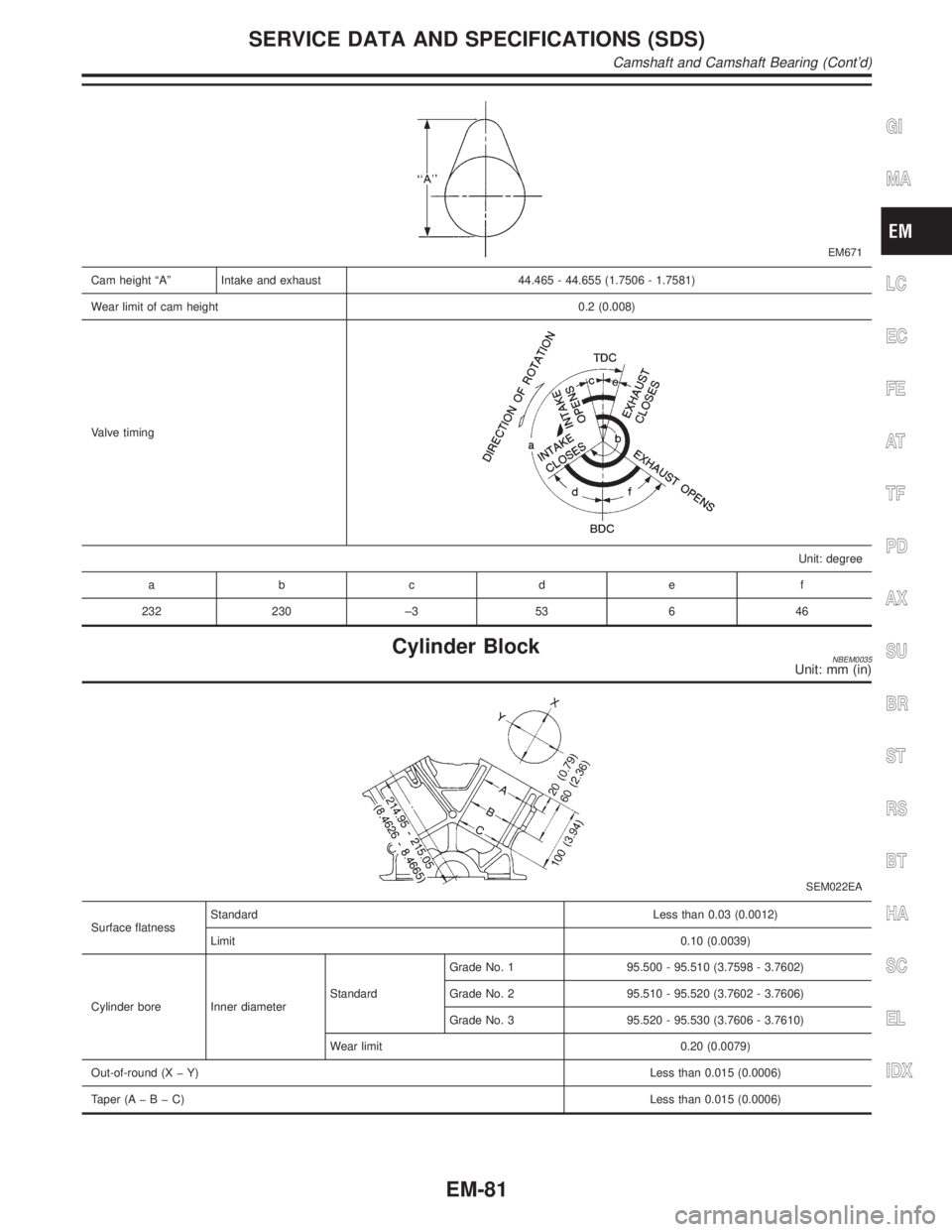
Cam height ªAº Intake and exhaust 44.465 - 44.655 (1.7506 - 1.7581)
Wear limit of cam height 0.2 (0.008)
Valve timing
Unit: degree
abcde f
232 230 ±3 53 6 46
Cylinder BlockNBEM0035Unit: mm (in)
SEM022EA
Surface flatnessStandardLess than 0.03 (0.0012)
Limit0.10 (0.0039)
Cylinder bore Inner diameterStandardGrade No. 1 95.500 - 95.510 (3.7598 - 3.7602)
Grade No. 2 95.510 - 95.520 (3.7602 - 3.7606)
Grade No. 3 95.520 - 95.530 (3.7606 - 3.7610)
Wear limit 0.20 (0.0079)
Out-of-round (X þ Y)Less than 0.015 (0.0006)
Taper (AþBþC)Less than 0.015 (0.0006)
GI
MA
LC
EC
FE
AT
TF
PD
AX
SU
BR
ST
RS
BT
HA
SC
EL
IDX
SERVICE DATA AND SPECIFICATIONS (SDS)
Camshaft and Camshaft Bearing (Cont'd)
EM-81
Page 1737 of 2395
Removal and InstallationNBFE0005CAUTION:
IAlways replace exhaust gaskets with new ones when reassembling.
IWith engine running, check all tube connections for exhaust gas leaks, and entire system for
unusual noises.
ICheck to ensure that mounting brackets and mounting insulators are installed properly and free
from undue stress. Improper installation could result in excessive noise or vibration.
IDiscard any heated oxygen sensor which has been dropped from a height of more than 0.5 m (19.7
in) onto a hard surface such as a concrete floor; use a new one.
IBefore installing new oxygen sensor, clean exhaust system threads using Oxygen Sensor Thread
Cleaner tool J-43897-18 of J-43897-12 and approved anti-seize lubricant.
IDo not overtorque the oxygen sensor. Doing so may cause damage to the oxygen sensor, result-
ing in the MIL coming on.
EXHAUST SYSTEM
Removal and Installation
FE-8
Page 1745 of 2395
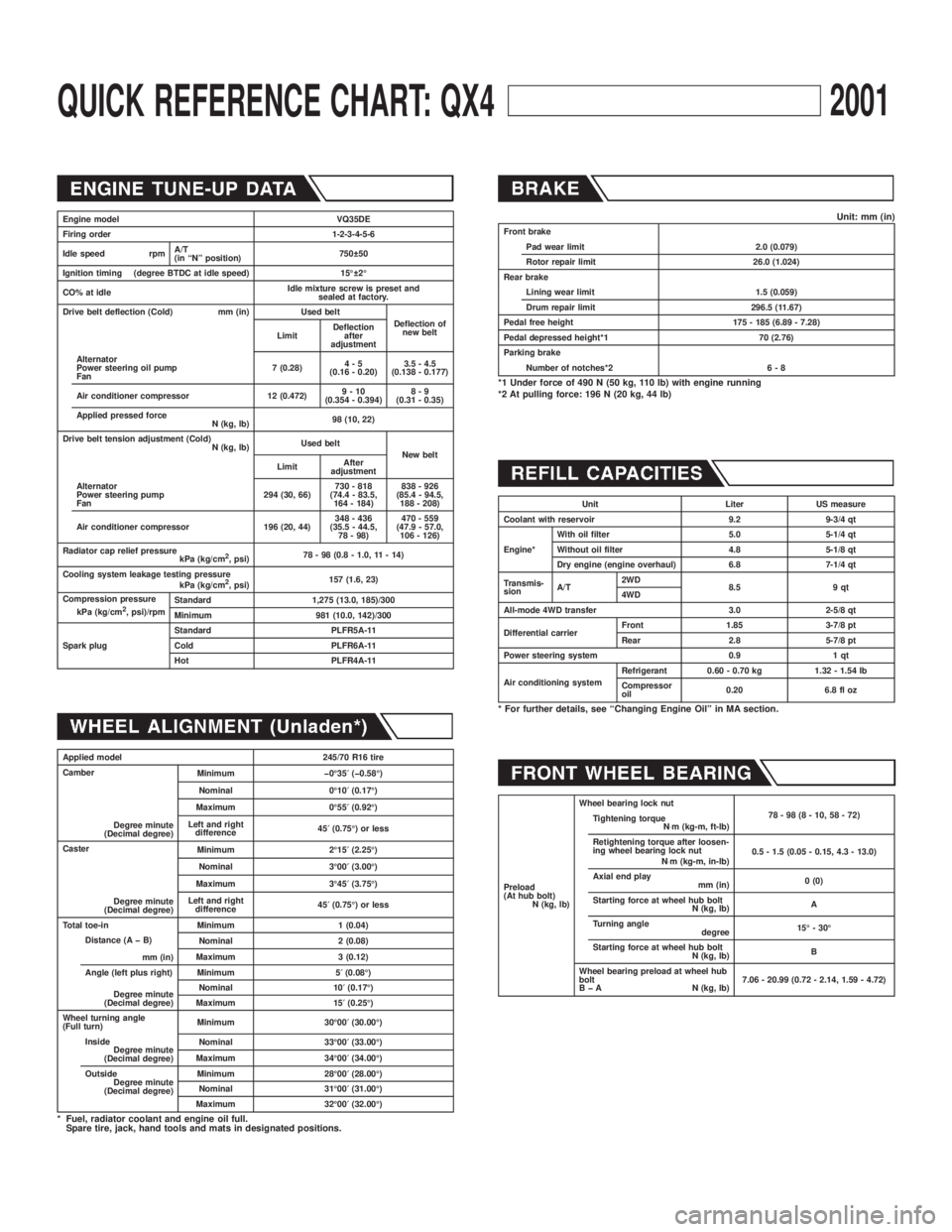
QUICK REFERENCE CHART: QX42001
Engine model VQ35DE
Firing order 1-2-3-4-5-6
Idle speed rpmA/T
(in ªNº position)750 50
Ignition timing (degree BTDC at idle speed) 15É 2É
CO% at idleIdle mixture screw is preset and
sealed at factory.
Drive belt deflection (Cold) mm (in) Used belt
Deflection of
new belt
LimitDeflection
after
adjustment
Alternator
Power steering oil pump
Fan7 (0.28)4-5
(0.16 - 0.20)3.5 - 4.5
(0.138 - 0.177)
Air conditioner compressor 12 (0.472)9-10
(0.354 - 0.394)8-9
(0.31 - 0.35)
Applied pressed force
N (kg, lb)98 (10, 22)
Drive belt tension adjustment (Cold)
N (kg, lb)Used belt
New belt
LimitAfter
adjustment
Alternator
Power steering pump
Fan294 (30, 66)730 - 818
(74.4 - 83.5,
164 - 184)838 - 926
(85.4 - 94.5,
188 - 208)
Air conditioner compressor 196 (20, 44)348 - 436
(35.5 - 44.5,
78 - 98)470 - 559
(47.9 - 57.0,
106 - 126)
Radiator cap relief pressure
kPa (kg/cm
2, psi)78 - 98 (0.8 - 1.0, 11 - 14)
Cooling system leakage testing pressure
kPa (kg/cm
2, psi)157 (1.6, 23)
Compression pressure
kPa (kg/cm
2, psi)/rpmStandard 1,275 (13.0, 185)/300
Minimum 981 (10.0, 142)/300
Spark plugStandard PLFR5A-11
Cold PLFR6A-11
Hot PLFR4A-11
Applied model 245/70 R16 tire
Camber
Degree minute
(Decimal degree)Minimum þ0É35¢(þ0.58É)
Nominal 0É10¢(0.17É)
Maximum 0É55¢(0.92É)
Left and right
difference45¢(0.75É) or less
Caster
Degree minute
(Decimal degree)Minimum 2É15¢(2.25É)
Nominal 3É00¢(3.00É)
Maximum 3É45¢(3.75É)
Left and right
difference45¢(0.75É) or less
Total toe-in Minimum 1 (0.04)
Distance (A þ B)
mm (in)Nominal 2 (0.08)
Maximum 3 (0.12)
Angle (left plus right)
Degree minute
(Decimal degree)Minimum 5¢(0.08É)
Nominal 10¢(0.17É)
Maximum 15¢(0.25É)
Wheel turning angle
(Full turn)Minimum 30É00¢(30.00É)
Inside
Degree minute
(Decimal degree)Nominal 33É00¢(33.00É)
Maximum 34É00¢(34.00É)
Outside
Degree minute
(Decimal degree)Minimum 28É00¢(28.00É)
Nominal 31É00¢(31.00É)
Maximum 32É00¢(32.00É)
* Fuel, radiator coolant and engine oil full.
Spare tire, jack, hand tools and mats in designated positions.
Unit: mm (in)Front brake
Pad wear limit 2.0 (0.079)
Rotor repair limit 26.0 (1.024)
Rear brake
Lining wear limit 1.5 (0.059)
Drum repair limit 296.5 (11.67)
Pedal free height 175 - 185 (6.89 - 7.28)
Pedal depressed height*1 70 (2.76)
Parking brake
Number of notches*2 6 - 8
*1 Under force of 490 N (50 kg, 110 lb) with engine running
*2 At pulling force: 196 N (20 kg, 44 lb)
Unit Liter US measure
Coolant with reservoir 9.2 9-3/4 qt
Engine*With oil filter 5.0 5-1/4 qt
Without oil filter 4.8 5-1/8 qt
Dry engine (engine overhaul) 6.8 7-1/4 qt
Transmis-
sionA/T2WD
8.5 9 qt
4WD
All-mode 4WD transfer 3.0 2-5/8 qt
Differential carrierFront 1.85 3-7/8 pt
Rear 2.8 5-7/8 pt
Power steering system 0.9 1 qt
Air conditioning systemRefrigerant 0.60 - 0.70 kg 1.32 - 1.54 lb
Compressor
oil0.20 6.8 fl oz
* For further details, see ªChanging Engine Oilº in MA section.
Preload
(At hub bolt)
N (kg, lb)Wheel bearing lock nut
78-98(8-10,58-72)
Tightening torque
N×m (kg-m, ft-lb)
Retightening torque after loosen-
ing wheel bearing lock nut
N×m (kg-m, in-lb)0.5 - 1.5 (0.05 - 0.15, 4.3 - 13.0)
Axial end play
mm (in)0 (0)
Starting force at wheel hub bolt
N (kg, lb)A
Turning angle
degree15É - 30É
Starting force at wheel hub bolt
N (kg, lb)B
Wheel bearing preload at wheel hub
bolt
B þ A N (kg, lb)7.06 - 20.99 (0.72 - 2.14, 1.59 - 4.72)