IDX INFINITI QX4 2001 Factory Service Manual
[x] Cancel search | Manufacturer: INFINITI, Model Year: 2001, Model line: QX4, Model: INFINITI QX4 2001Pages: 2395, PDF Size: 43.2 MB
Page 1706 of 2395
SEM965A
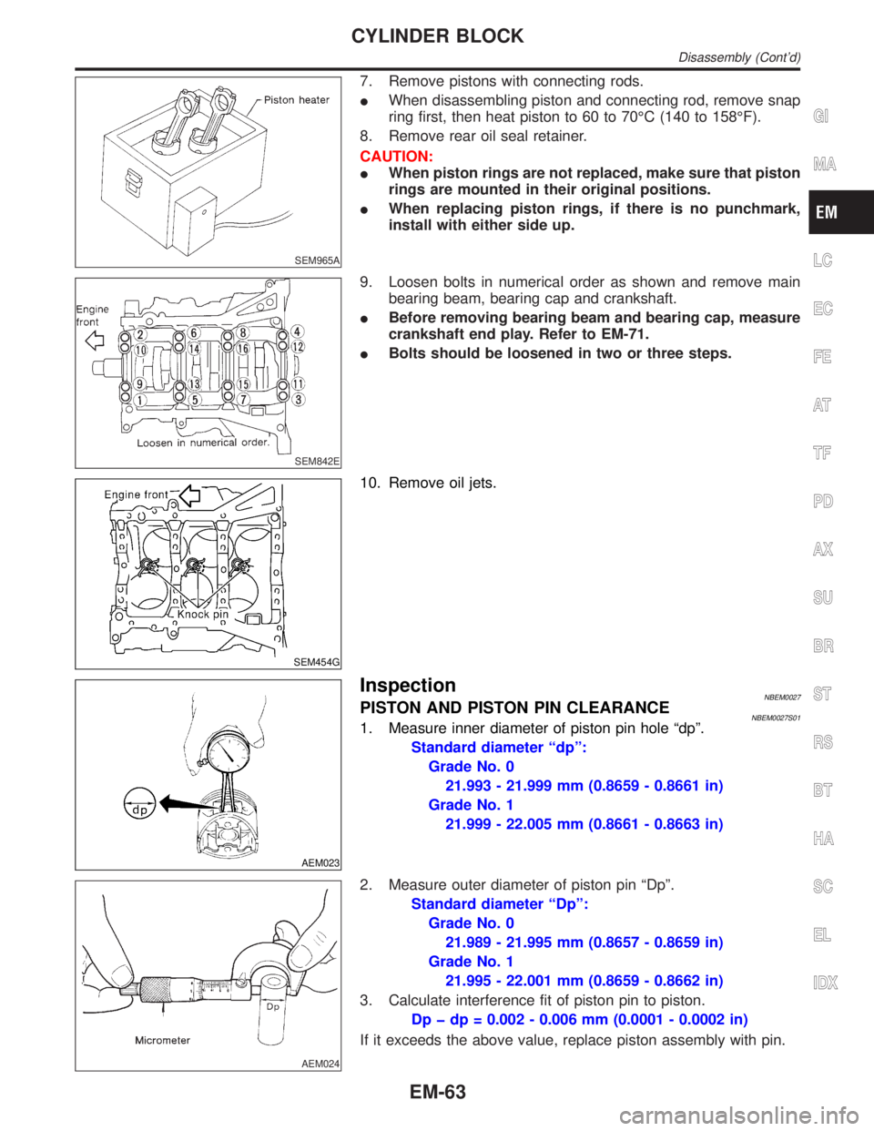
7. Remove pistons with connecting rods.
IWhen disassembling piston and connecting rod, remove snap
ring first, then heat piston to 60 to 70ÉC (140 to 158ÉF).
8. Remove rear oil seal retainer.
CAUTION:
IWhen piston rings are not replaced, make sure that piston
rings are mounted in their original positions.
IWhen replacing piston rings, if there is no punchmark,
install with either side up.
SEM842E
9. Loosen bolts in numerical order as shown and remove main
bearing beam, bearing cap and crankshaft.
IBefore removing bearing beam and bearing cap, measure
crankshaft end play. Refer to EM-71.
IBolts should be loosened in two or three steps.
SEM454G
10. Remove oil jets.
AEM023
InspectionNBEM0027PISTON AND PISTON PIN CLEARANCENBEM0027S011. Measure inner diameter of piston pin hole ªdpº.
Standard diameter ªdpº:
Grade No. 0
21.993 - 21.999 mm (0.8659 - 0.8661 in)
Grade No. 1
21.999 - 22.005 mm (0.8661 - 0.8663 in)
AEM024
2. Measure outer diameter of piston pin ªDpº.
Standard diameter ªDpº:
Grade No. 0
21.989 - 21.995 mm (0.8657 - 0.8659 in)
Grade No. 1
21.995 - 22.001 mm (0.8659 - 0.8662 in)
3. Calculate interference fit of piston pin to piston.
Dp þ dp = 0.002 - 0.006 mm (0.0001 - 0.0002 in)
If it exceeds the above value, replace piston assembly with pin.
GI
MA
LC
EC
FE
AT
TF
PD
AX
SU
BR
ST
RS
BT
HA
SC
EL
IDX
CYLINDER BLOCK
Disassembly (Cont'd)
EM-63
Page 1708 of 2395
SEM038F
SEM003F
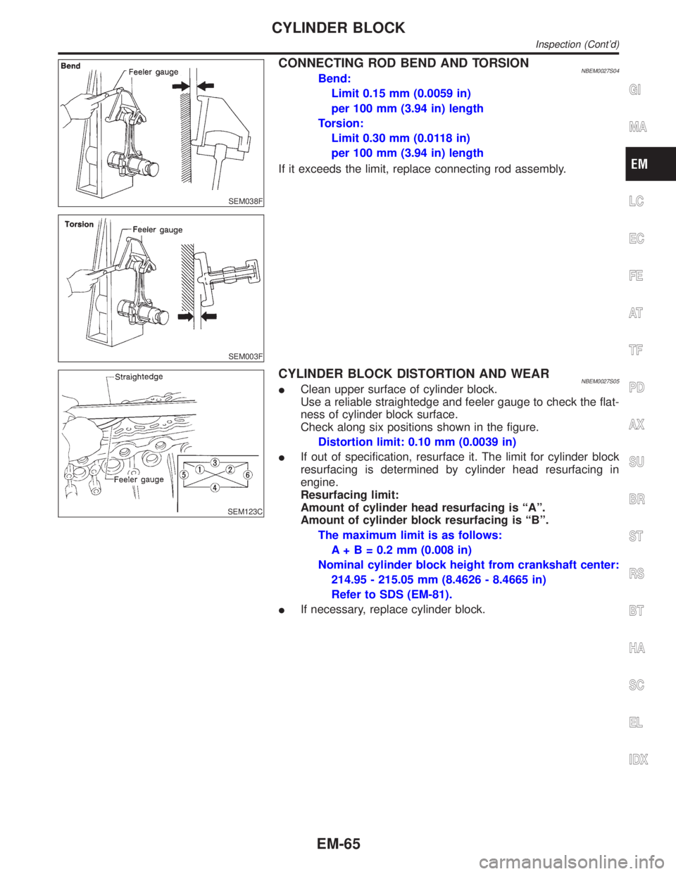
CONNECTING ROD BEND AND TORSIONNBEM0027S04Bend:
Limit 0.15 mm (0.0059 in)
per 100 mm (3.94 in) length
Torsion:
Limit 0.30 mm (0.0118 in)
per 100 mm (3.94 in) length
If it exceeds the limit, replace connecting rod assembly.
SEM123C
CYLINDER BLOCK DISTORTION AND WEARNBEM0027S05IClean upper surface of cylinder block.
Use a reliable straightedge and feeler gauge to check the flat-
ness of cylinder block surface.
Check along six positions shown in the figure.
Distortion limit: 0.10 mm (0.0039 in)
IIf out of specification, resurface it. The limit for cylinder block
resurfacing is determined by cylinder head resurfacing in
engine.
Resurfacing limit:
Amount of cylinder head resurfacing is ªAº.
Amount of cylinder block resurfacing is ªBº.
The maximum limit is as follows:
A + B = 0.2 mm (0.008 in)
Nominal cylinder block height from crankshaft center:
214.95 - 215.05 mm (8.4626 - 8.4665 in)
Refer to SDS (EM-81).
IIf necessary, replace cylinder block.
GI
MA
LC
EC
FE
AT
TF
PD
AX
SU
BR
ST
RS
BT
HA
SC
EL
IDX
CYLINDER BLOCK
Inspection (Cont'd)
EM-65
Page 1710 of 2395
8. Cut cylinder bores.
IWhen any cylinder needs boring, all other cylinders must
also be bored.
IDo not cut too much out of cylinder bore at a time. Cut
only 0.05 mm (0.0020 in) or so in diameter at a time.
9. Hone cylinders to obtain specified piston-to-bore clearance.
10. Measure finished cylinder bore for out-of-round and taper.
IMeasurement should be done after cylinder bore cools
down.
SEM316A
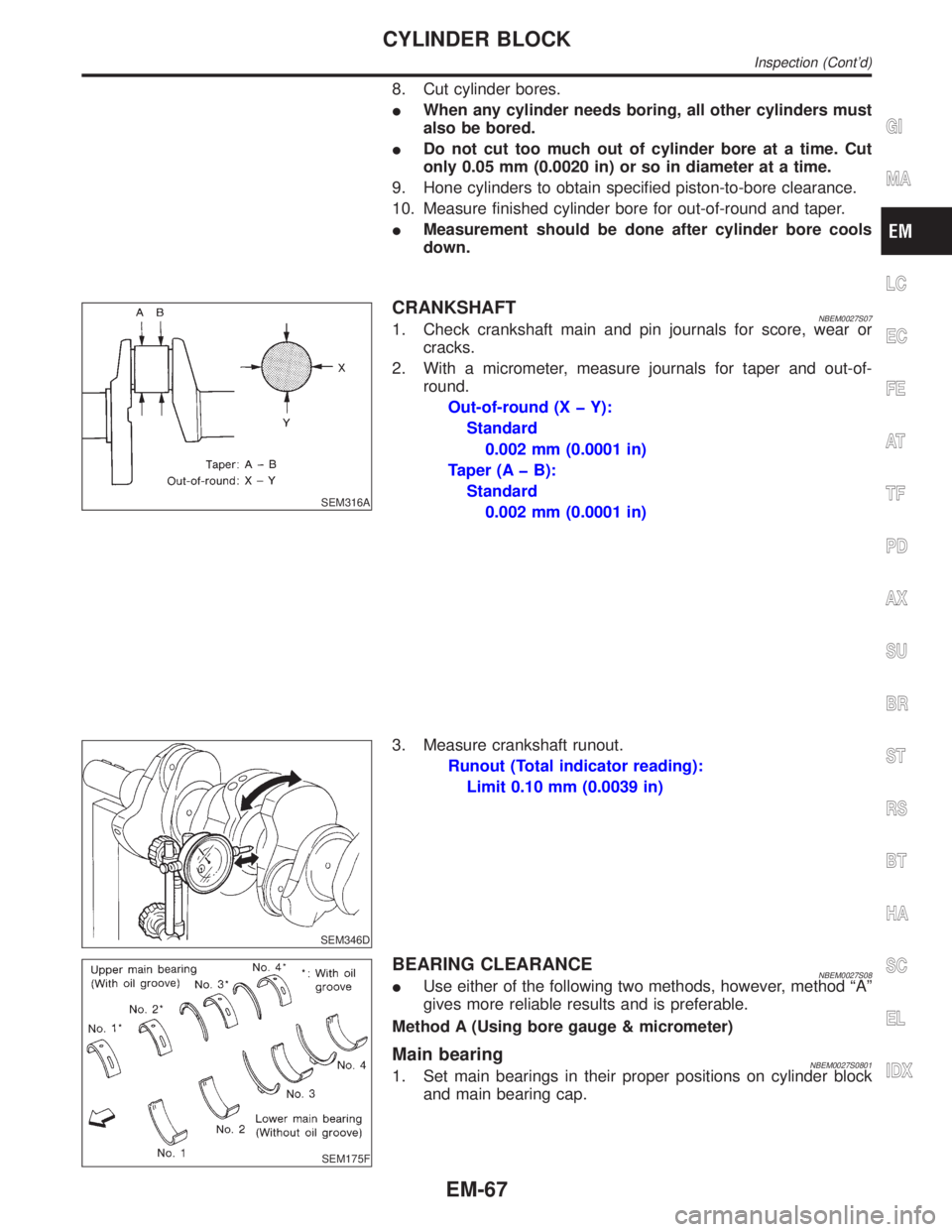
CRANKSHAFTNBEM0027S071. Check crankshaft main and pin journals for score, wear or
cracks.
2. With a micrometer, measure journals for taper and out-of-
round.
Out-of-round (X þ Y):
Standard
0.002 mm (0.0001 in)
Taper (A þ B):
Standard
0.002 mm (0.0001 in)
SEM346D
3. Measure crankshaft runout.
Runout (Total indicator reading):
Limit 0.10 mm (0.0039 in)
SEM175F
BEARING CLEARANCENBEM0027S08IUse either of the following two methods, however, method ªAº
gives more reliable results and is preferable.
Method A (Using bore gauge & micrometer)
Main bearingNBEM0027S08011. Set main bearings in their proper positions on cylinder block
and main bearing cap.
GI
MA
LC
EC
FE
AT
TF
PD
AX
SU
BR
ST
RS
BT
HA
SC
EL
IDX
CYLINDER BLOCK
Inspection (Cont'd)
EM-67
Page 1712 of 2395
SEM280G
AEM027
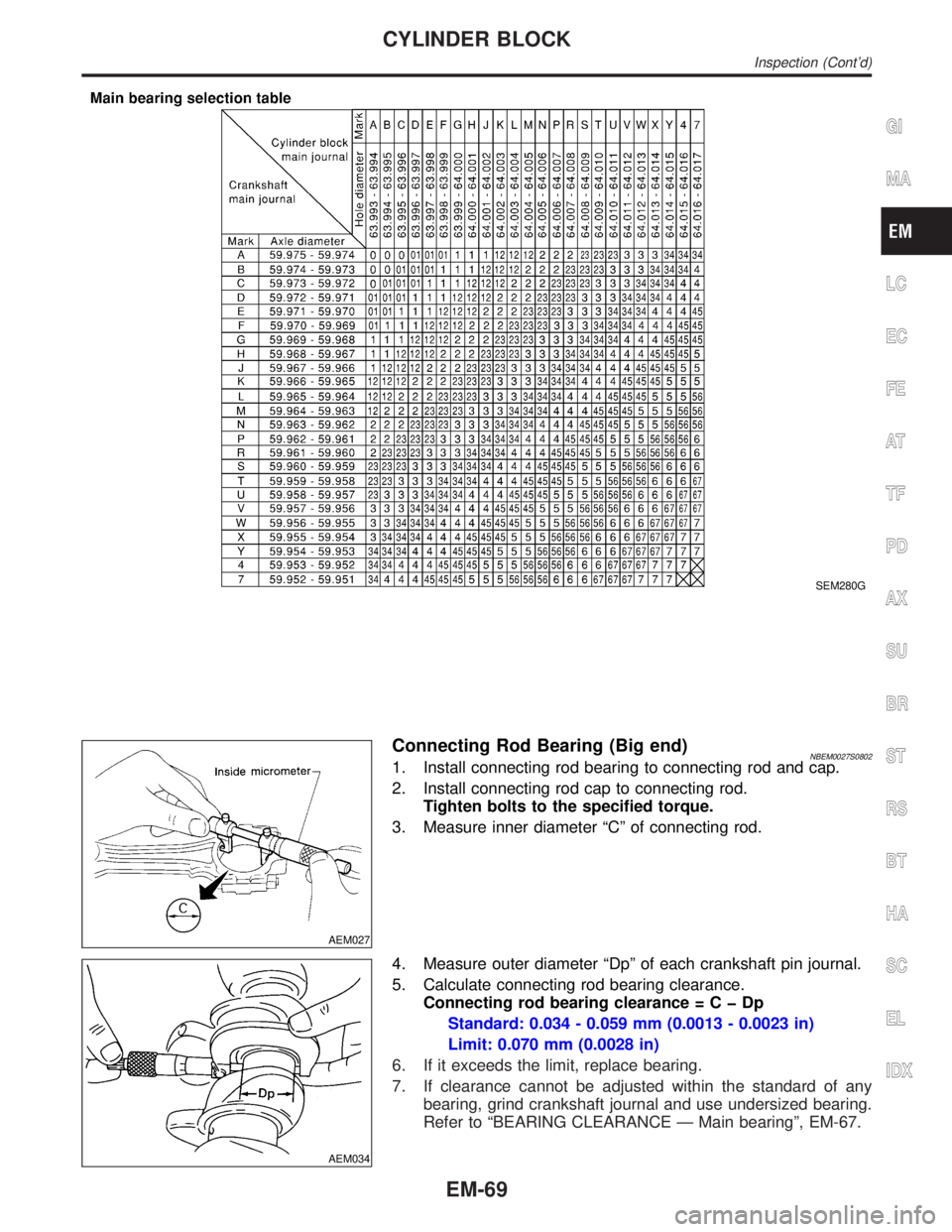
Connecting Rod Bearing (Big end)NBEM0027S08021. Install connecting rod bearing to connecting rod and cap.
2. Install connecting rod cap to connecting rod.
Tighten bolts to the specified torque.
3. Measure inner diameter ªCº of connecting rod.
AEM034
4. Measure outer diameter ªDpº of each crankshaft pin journal.
5. Calculate connecting rod bearing clearance.
Connecting rod bearing clearance=CþDp
Standard: 0.034 - 0.059 mm (0.0013 - 0.0023 in)
Limit: 0.070 mm (0.0028 in)
6. If it exceeds the limit, replace bearing.
7. If clearance cannot be adjusted within the standard of any
bearing, grind crankshaft journal and use undersized bearing.
Refer to ªBEARING CLEARANCE Ð Main bearingº, EM-67.
GI
MA
LC
EC
FE
AT
TF
PD
AX
SU
BR
ST
RS
BT
HA
SC
EL
IDX
CYLINDER BLOCK
Inspection (Cont'd)
EM-69
Page 1714 of 2395
SEM838F
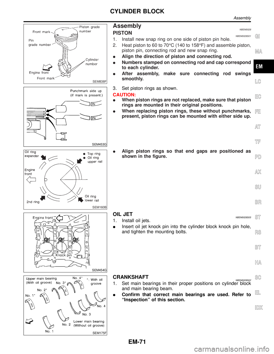
AssemblyNBEM0028PISTONNBEM0028S011. Install new snap ring on one side of piston pin hole.
2. Heat piston to 60 to 70ÉC (140 to 158ÉF) and assemble piston,
piston pin, connecting rod and new snap ring.
IAlign the direction of piston and connecting rod.
INumbers stamped on connecting rod and cap correspond
to each cylinder.
IAfter assembly, make sure connecting rod swings
smoothly.
SEM453G
3. Set piston rings as shown.
CAUTION:
IWhen piston rings are not replaced, make sure that piston
rings are mounted in their original positions.
IWhen replacing piston rings, these without punchmarks,
present, piston rings can be mounted with either side up.
SEM160B
IAlign piston rings so that end gaps are positioned as
shown in the figure.
SEM454G
OIL JETNBEM0028S051. Install oil jets.
IInsert oil jet knock pin into the cylinder block knock pin hole,
and tighten the mounting bolts.
SEM175F
CRANKSHAFTNBEM0028S021. Set main bearings in their proper positions on cylinder block
and main bearing beam.
IConfirm that correct main bearings are used. Refer to
ªInspectionº of this section.
GI
MA
LC
EC
FE
AT
TF
PD
AX
SU
BR
ST
RS
BT
HA
SC
EL
IDX
CYLINDER BLOCK
Assembly
EM-71
Page 1716 of 2395
SEM455G
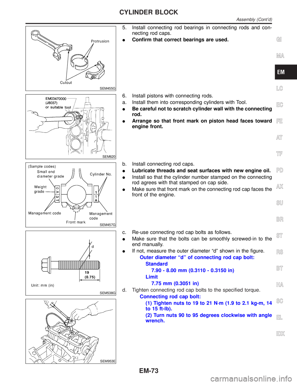
5. Install connecting rod bearings in connecting rods and con-
necting rod caps.
IConfirm that correct bearings are used.
SEM620
6. Install pistons with connecting rods.
a. Install them into corresponding cylinders with Tool.
IBe careful not to scratch cylinder wall with the connecting
rod.
IArrange so that front mark on piston head faces toward
engine front.
SEM457G
b. Install connecting rod caps.
ILubricate threads and seat surfaces with new engine oil.
IInstall so that the cylinder number stamped on the connecting
rod agrees with that stamped on cap side.
IMake sure that front mark on the connecting rod cap faces the
front of the engine.
SEM538G
SEM953E
c. Re-use connecting rod cap bolts as follows.
IMake sure that the bolts can be smoothly screwed-in to the
end manually.
IIf not, measure the outer diameter ªdº shown in the figure.
Outer diameter ªdº of connecting rod cap bolt:
Standard
7.90 - 8.00 mm (0.3110 - 0.3150 in)
Limit
7.75 mm (0.3051 in)
d. Tighten connecting rod cap bolts to the specified torque.
Connecting rod cap bolt:
(1) Tighten nuts to 19 to 21 N´m (1.9 to 2.1 kg-m, 14
to 15 ft-lb).
(2) Turn nuts 90 to 95 degrees clockwise with angle
wrench.
GI
MA
LC
EC
FE
AT
TF
PD
AX
SU
BR
ST
RS
BT
HA
SC
EL
IDX
CYLINDER BLOCK
Assembly (Cont'd)
EM-73
Page 1718 of 2395
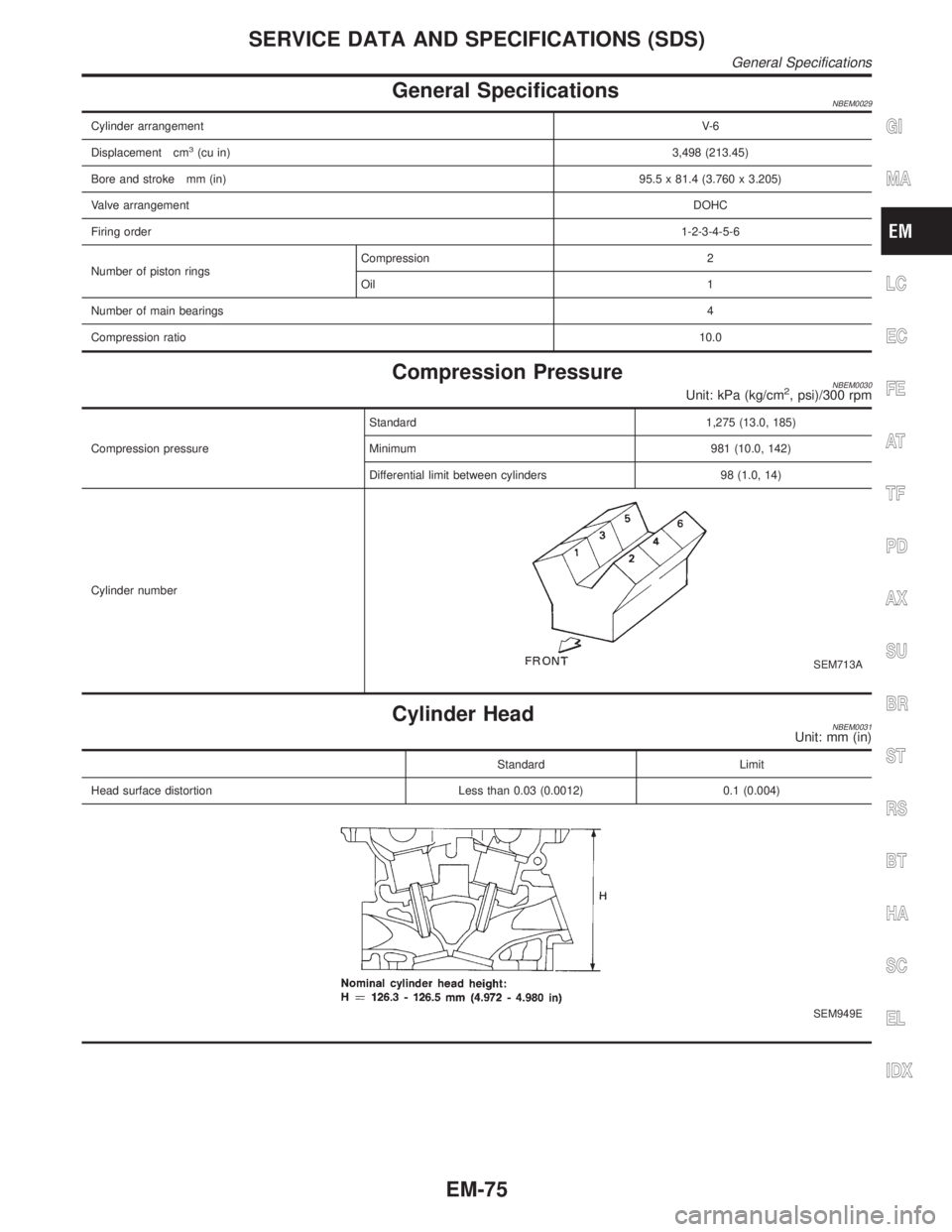
General SpecificationsNBEM0029
Cylinder arrangementV- 6
Displacement cm
3(cu in)3,498 (213.45)
Bore and stroke mm (in)95.5 x 81.4 (3.760 x 3.205)
Valve arrangementDOHC
Firing order1-2-3-4-5-6
Number of piston ringsCompression 2
Oil 1
Number of main bearings4
Compression ratio10.0
Compression PressureNBEM0030Unit: kPa (kg/cm2, psi)/300 rpm
Compression pressureStandard 1,275 (13.0, 185)
Minimum 981 (10.0, 142)
Differential limit between cylinders 98 (1.0, 14)
Cylinder number
SEM713A
Cylinder HeadNBEM0031Unit: mm (in)
Standard Limit
Head surface distortion Less than 0.03 (0.0012) 0.1 (0.004)
SEM949E
GI
MA
LC
EC
FE
AT
TF
PD
AX
SU
BR
ST
RS
BT
HA
SC
EL
IDX
SERVICE DATA AND SPECIFICATIONS (SDS)
General Specifications
EM-75
Page 1720 of 2395
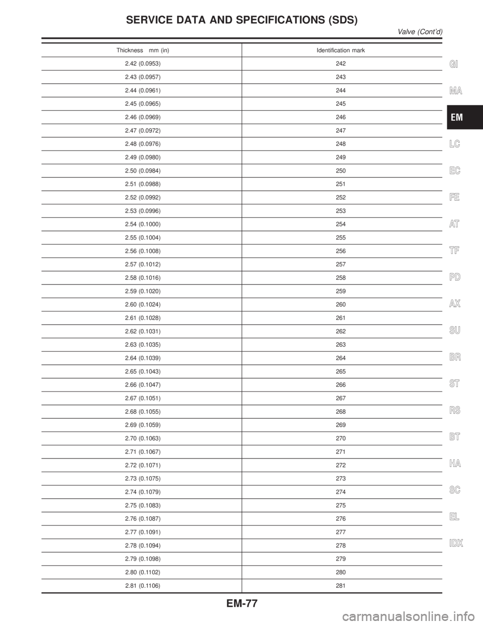
Thickness mm (in) Identification mark
2.42 (0.0953) 242
2.43 (0.0957) 243
2.44 (0.0961) 244
2.45 (0.0965) 245
2.46 (0.0969) 246
2.47 (0.0972) 247
2.48 (0.0976) 248
2.49 (0.0980) 249
2.50 (0.0984) 250
2.51 (0.0988) 251
2.52 (0.0992) 252
2.53 (0.0996) 253
2.54 (0.1000) 254
2.55 (0.1004) 255
2.56 (0.1008) 256
2.57 (0.1012) 257
2.58 (0.1016) 258
2.59 (0.1020) 259
2.60 (0.1024) 260
2.61 (0.1028) 261
2.62 (0.1031) 262
2.63 (0.1035) 263
2.64 (0.1039) 264
2.65 (0.1043) 265
2.66 (0.1047) 266
2.67 (0.1051) 267
2.68 (0.1055) 268
2.69 (0.1059) 269
2.70 (0.1063) 270
2.71 (0.1067) 271
2.72 (0.1071) 272
2.73 (0.1075) 273
2.74 (0.1079) 274
2.75 (0.1083) 275
2.76 (0.1087) 276
2.77 (0.1091) 277
2.78 (0.1094) 278
2.79 (0.1098) 279
2.80 (0.1102) 280
2.81 (0.1106) 281
GI
MA
LC
EC
FE
AT
TF
PD
AX
SU
BR
ST
RS
BT
HA
SC
EL
IDX
SERVICE DATA AND SPECIFICATIONS (SDS)
Valve (Cont'd)
EM-77
Page 1722 of 2395
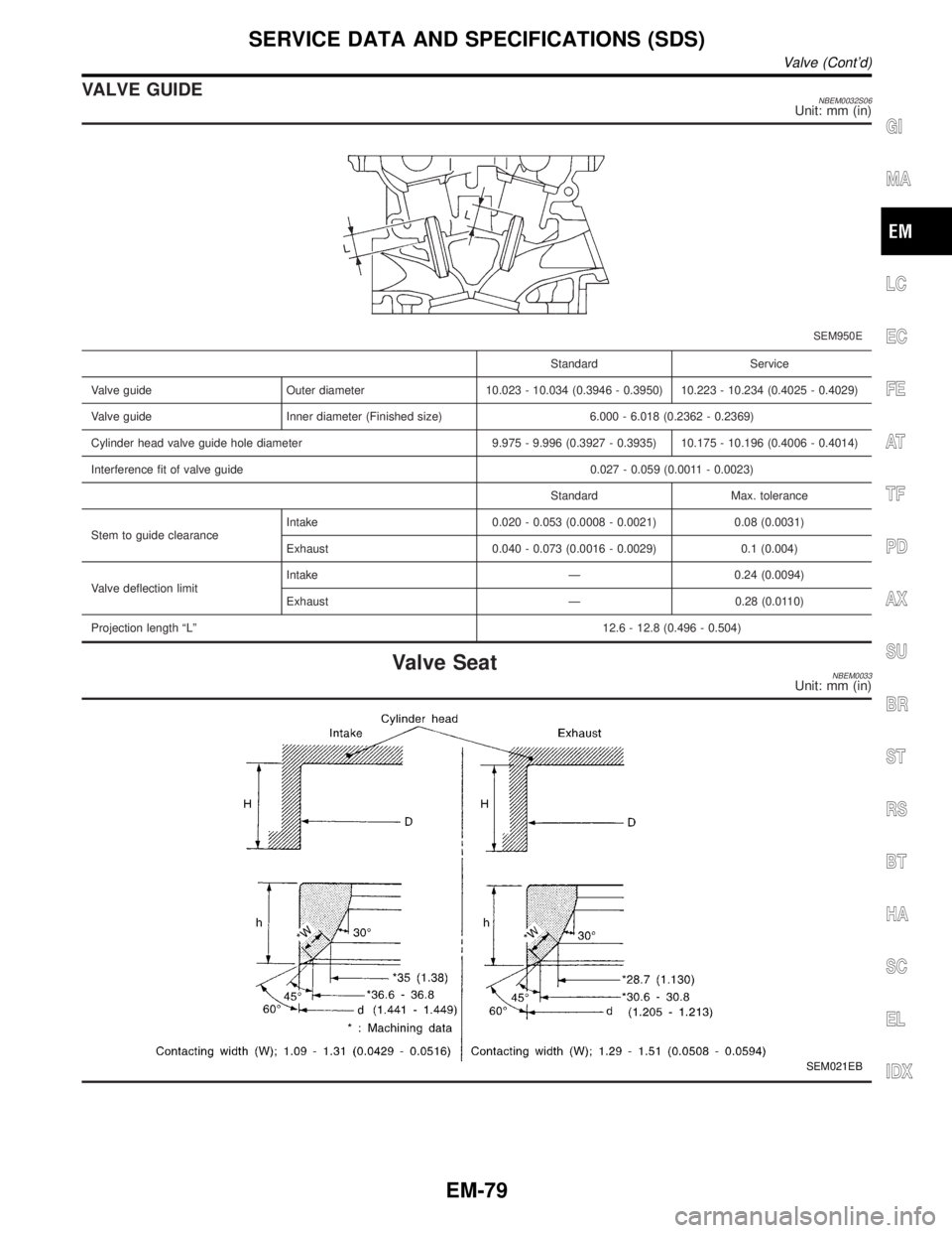
VALVE GUIDENBEM0032S06Unit: mm (in)
SEM950E
Standard Service
Valve guide Outer diameter 10.023 - 10.034 (0.3946 - 0.3950) 10.223 - 10.234 (0.4025 - 0.4029)
Valve guide Inner diameter (Finished size) 6.000 - 6.018 (0.2362 - 0.2369)
Cylinder head valve guide hole diameter 9.975 - 9.996 (0.3927 - 0.3935) 10.175 - 10.196 (0.4006 - 0.4014)
Interference fit of valve guide 0.027 - 0.059 (0.0011 - 0.0023)
Standard Max. tolerance
Stem to guide clearanceIntake 0.020 - 0.053 (0.0008 - 0.0021) 0.08 (0.0031)
Exhaust 0.040 - 0.073 (0.0016 - 0.0029) 0.1 (0.004)
Valve deflection limitIntake Ð 0.24 (0.0094)
Exhaust Ð 0.28 (0.0110)
Projection length ªLº12.6 - 12.8 (0.496 - 0.504)
Valve SeatNBEM0033Unit: mm (in)
SEM021EB
GI
MA
LC
EC
FE
AT
TF
PD
AX
SU
BR
ST
RS
BT
HA
SC
EL
IDX
SERVICE DATA AND SPECIFICATIONS (SDS)
Valve (Cont'd)
EM-79
Page 1724 of 2395
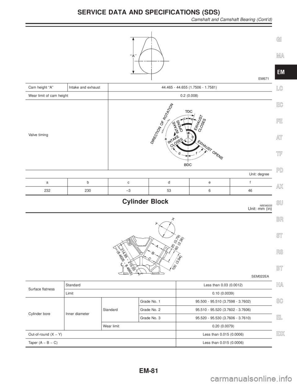
EM671
Cam height ªAº Intake and exhaust 44.465 - 44.655 (1.7506 - 1.7581)
Wear limit of cam height 0.2 (0.008)
Valve timing
Unit: degree
abcde f
232 230 ±3 53 6 46
Cylinder BlockNBEM0035Unit: mm (in)
SEM022EA
Surface flatnessStandardLess than 0.03 (0.0012)
Limit0.10 (0.0039)
Cylinder bore Inner diameterStandardGrade No. 1 95.500 - 95.510 (3.7598 - 3.7602)
Grade No. 2 95.510 - 95.520 (3.7602 - 3.7606)
Grade No. 3 95.520 - 95.530 (3.7606 - 3.7610)
Wear limit 0.20 (0.0079)
Out-of-round (X þ Y)Less than 0.015 (0.0006)
Taper (AþBþC)Less than 0.015 (0.0006)
GI
MA
LC
EC
FE
AT
TF
PD
AX
SU
BR
ST
RS
BT
HA
SC
EL
IDX
SERVICE DATA AND SPECIFICATIONS (SDS)
Camshaft and Camshaft Bearing (Cont'd)
EM-81