IDX INFINITI QX4 2001 Factory Service Manual
[x] Cancel search | Manufacturer: INFINITI, Model Year: 2001, Model line: QX4, Model: INFINITI QX4 2001Pages: 2395, PDF Size: 43.2 MB
Page 1792 of 2395
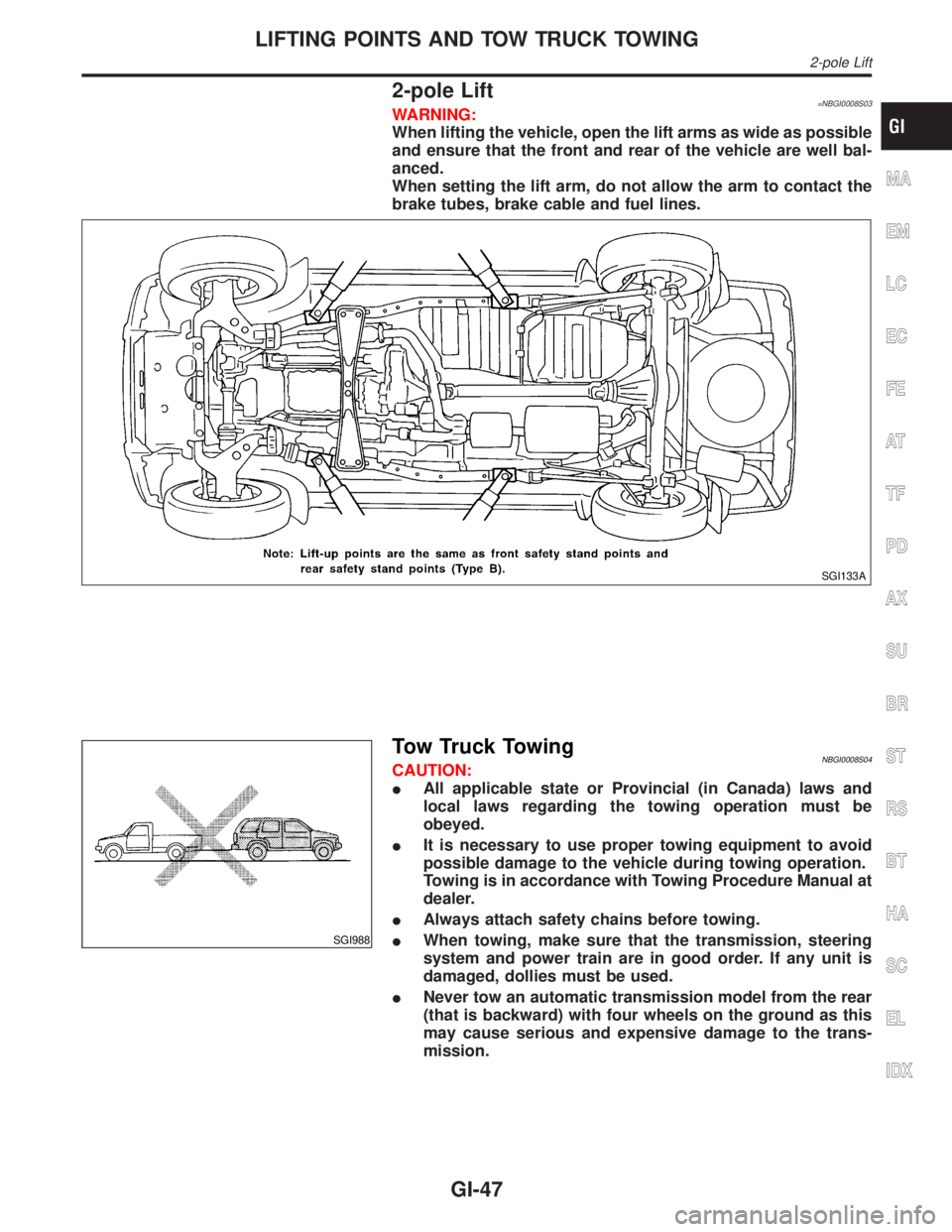
2-pole Lift=NBGI0008S03WARNING:
When lifting the vehicle, open the lift arms as wide as possible
and ensure that the front and rear of the vehicle are well bal-
anced.
When setting the lift arm, do not allow the arm to contact the
brake tubes, brake cable and fuel lines.
SGI133A
SGI988
Tow Truck TowingNBGI0008S04CAUTION:
IAll applicable state or Provincial (in Canada) laws and
local laws regarding the towing operation must be
obeyed.
IIt is necessary to use proper towing equipment to avoid
possible damage to the vehicle during towing operation.
Towing is in accordance with Towing Procedure Manual at
dealer.
IAlways attach safety chains before towing.
IWhen towing, make sure that the transmission, steering
system and power train are in good order. If any unit is
damaged, dollies must be used.
INever tow an automatic transmission model from the rear
(that is backward) with four wheels on the ground as this
may cause serious and expensive damage to the trans-
mission.
MA
EM
LC
EC
FE
AT
TF
PD
AX
SU
BR
ST
RS
BT
HA
SC
EL
IDX
LIFTING POINTS AND TOW TRUCK TOWING
2-pole Lift
GI-47
Page 1794 of 2395
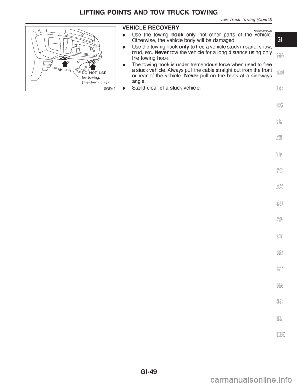
SGI949
VEHICLE RECOVERYNBGI0008S0401IUse the towinghookonly, not other parts of the vehicle.
Otherwise, the vehicle body will be damaged.
IUse the towing hookonlyto free a vehicle stuck in sand, snow,
mud, etc.Nevertow the vehicle for a long distance using only
the towing hook.
IThe towing hook is under tremendous force when used to free
a stuck vehicle. Always pull the cable straight out from the front
or rear of the vehicle.Neverpull on the hook at a sideways
angle.
IStand clear of a stuck vehicle.
MA
EM
LC
EC
FE
AT
TF
PD
AX
SU
BR
ST
RS
BT
HA
SC
EL
IDX
LIFTING POINTS AND TOW TRUCK TOWING
Tow Truck Towing (Cont'd)
GI-49
Page 1796 of 2395
NBGI0010
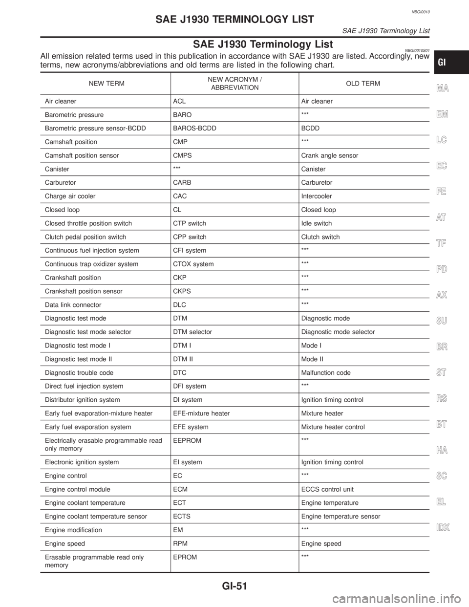
SAE J1930 Terminology ListNBGI0010S01All emission related terms used in this publication in accordance with SAE J1930 are listed. Accordingly, new
terms, new acronyms/abbreviations and old terms are listed in the following chart.
NEW TERMNEW ACRONYM /
ABBREVIATIONOLD TERM
Air cleaner ACL Air cleaner
Barometric pressure BARO ***
Barometric pressure sensor-BCDD BAROS-BCDD BCDD
Camshaft position CMP ***
Camshaft position sensor CMPS Crank angle sensor
Canister *** Canister
Carburetor CARB Carburetor
Charge air cooler CAC Intercooler
Closed loop CL Closed loop
Closed throttle position switch CTP switch Idle switch
Clutch pedal position switch CPP switch Clutch switch
Continuous fuel injection system CFI system ***
Continuous trap oxidizer system CTOX system ***
Crankshaft position CKP ***
Crankshaft position sensor CKPS ***
Data link connector DLC ***
Diagnostic test mode DTM Diagnostic mode
Diagnostic test mode selector DTM selector Diagnostic mode selector
Diagnostic test mode I DTM I Mode I
Diagnostic test mode II DTM II Mode II
Diagnostic trouble code DTC Malfunction code
Direct fuel injection system DFI system ***
Distributor ignition system DI system Ignition timing control
Early fuel evaporation-mixture heater EFE-mixture heater Mixture heater
Early fuel evaporation system EFE system Mixture heater control
Electrically erasable programmable read
only memoryEEPROM ***
Electronic ignition system EI system Ignition timing control
Engine control EC ***
Engine control module ECM ECCS control unit
Engine coolant temperature ECT Engine temperature
Engine coolant temperature sensor ECTS Engine temperature sensor
Engine modification EM ***
Engine speed RPM Engine speed
Erasable programmable read only
memoryEPROM ***MA
EM
LC
EC
FE
AT
TF
PD
AX
SU
BR
ST
RS
BT
HA
SC
EL
IDX
SAE J1930 TERMINOLOGY LIST
SAE J1930 Terminology List
GI-51
Page 1798 of 2395
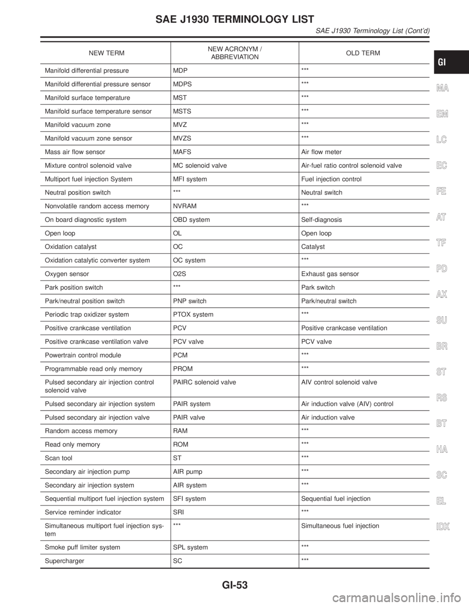
NEW TERMNEW ACRONYM /
ABBREVIATIONOLD TERM
Manifold differential pressure MDP ***
Manifold differential pressure sensor MDPS ***
Manifold surface temperature MST ***
Manifold surface temperature sensor MSTS ***
Manifold vacuum zone MVZ ***
Manifold vacuum zone sensor MVZS ***
Mass air flow sensor MAFS Air flow meter
Mixture control solenoid valve MC solenoid valve Air-fuel ratio control solenoid valve
Multiport fuel injection System MFI system Fuel injection control
Neutral position switch *** Neutral switch
Nonvolatile random access memory NVRAM ***
On board diagnostic system OBD system Self-diagnosis
Open loop OL Open loop
Oxidation catalyst OC Catalyst
Oxidation catalytic converter system OC system ***
Oxygen sensor O2S Exhaust gas sensor
Park position switch *** Park switch
Park/neutral position switch PNP switch Park/neutral switch
Periodic trap oxidizer system PTOX system ***
Positive crankcase ventilation PCV Positive crankcase ventilation
Positive crankcase ventilation valve PCV valve PCV valve
Powertrain control module PCM ***
Programmable read only memory PROM ***
Pulsed secondary air injection control
solenoid valvePAIRC solenoid valve AIV control solenoid valve
Pulsed secondary air injection system PAIR system Air induction valve (AIV) control
Pulsed secondary air injection valve PAIR valve Air induction valve
Random access memory RAM ***
Read only memory ROM ***
Scan tool ST ***
Secondary air injection pump AIR pump ***
Secondary air injection system AIR system ***
Sequential multiport fuel injection system SFI system Sequential fuel injection
Service reminder indicator SRI ***
Simultaneous multiport fuel injection sys-
tem*** Simultaneous fuel injection
Smoke puff limiter system SPL system ***
Supercharger SC ***
MA
EM
LC
EC
FE
AT
TF
PD
AX
SU
BR
ST
RS
BT
HA
SC
EL
IDX
SAE J1930 TERMINOLOGY LIST
SAE J1930 Terminology List (Cont'd)
GI-53
Page 1800 of 2395
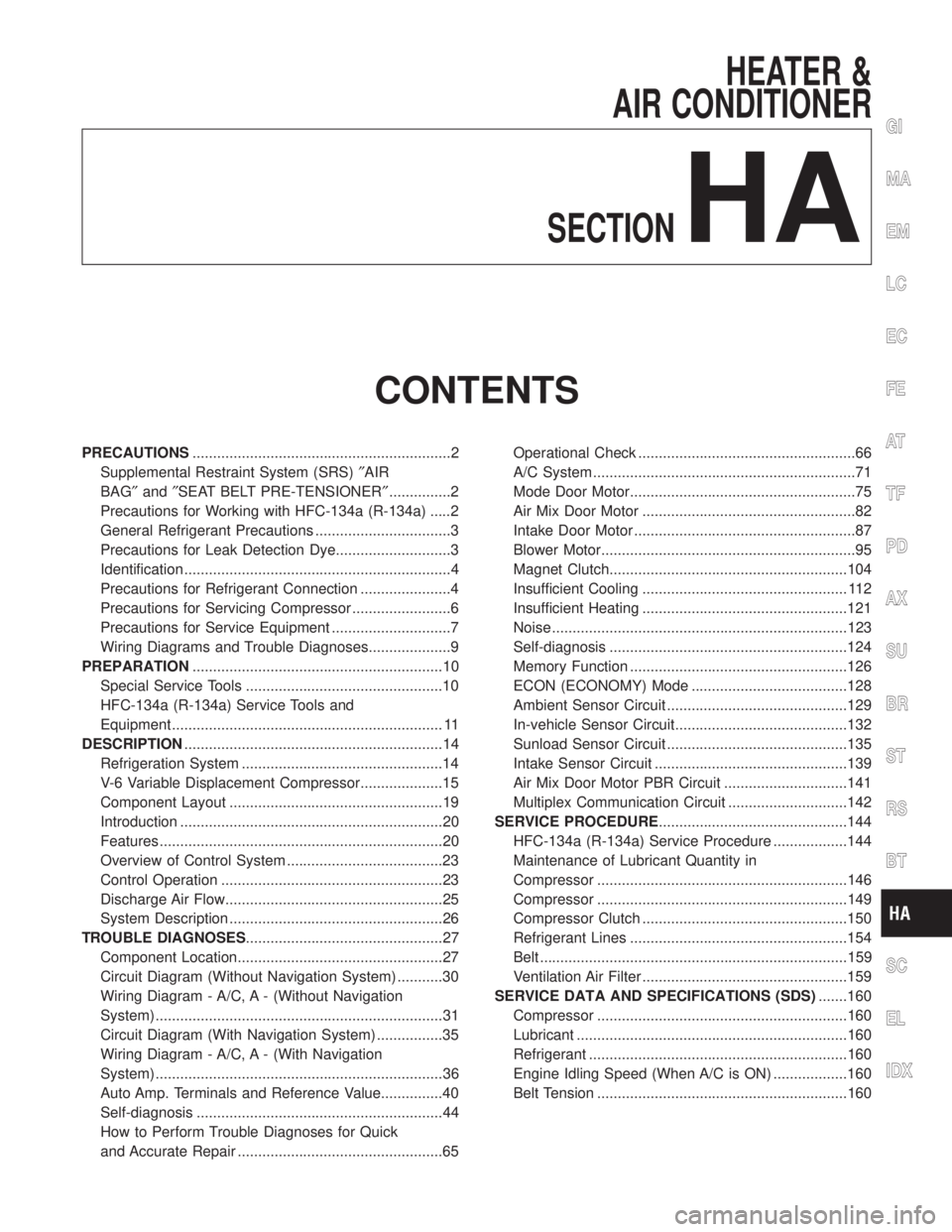
HEATER &
AIR CONDITIONER
SECTION
HA
CONTENTS
PRECAUTIONS...............................................................2
Supplemental Restraint System (SRS)²AIR
BAG²and²SEAT BELT PRE-TENSIONER²...............2
Precautions for Working with HFC-134a (R-134a) .....2
General Refrigerant Precautions .................................3
Precautions for Leak Detection Dye............................3
Identification .................................................................4
Precautions for Refrigerant Connection ......................4
Precautions for Servicing Compressor ........................6
Precautions for Service Equipment .............................7
Wiring Diagrams and Trouble Diagnoses....................9
PREPARATION.............................................................10
Special Service Tools ................................................10
HFC-134a (R-134a) Service Tools and
Equipment .................................................................. 11
DESCRIPTION...............................................................14
Refrigeration System .................................................14
V-6 Variable Displacement Compressor....................15
Component Layout ....................................................19
Introduction ................................................................20
Features .....................................................................20
Overview of Control System ......................................23
Control Operation ......................................................23
Discharge Air Flow.....................................................25
System Description ....................................................26
TROUBLE DIAGNOSES................................................27
Component Location..................................................27
Circuit Diagram (Without Navigation System) ...........30
Wiring Diagram - A/C, A - (Without Navigation
System) ......................................................................31
Circuit Diagram (With Navigation System) ................35
Wiring Diagram - A/C, A - (With Navigation
System) ......................................................................36
Auto Amp. Terminals and Reference Value...............40
Self-diagnosis ............................................................44
How to Perform Trouble Diagnoses for Quick
and Accurate Repair ..................................................65Operational Check .....................................................66
A/C System ................................................................71
Mode Door Motor.......................................................75
Air Mix Door Motor ....................................................82
Intake Door Motor ......................................................87
Blower Motor..............................................................95
Magnet Clutch..........................................................104
Insufficient Cooling .................................................. 112
Insufficient Heating ..................................................121
Noise ........................................................................123
Self-diagnosis ..........................................................124
Memory Function .....................................................126
ECON (ECONOMY) Mode ......................................128
Ambient Sensor Circuit ............................................129
In-vehicle Sensor Circuit..........................................132
Sunload Sensor Circuit ............................................135
Intake Sensor Circuit ...............................................139
Air Mix Door Motor PBR Circuit ..............................141
Multiplex Communication Circuit .............................142
SERVICE PROCEDURE..............................................144
HFC-134a (R-134a) Service Procedure ..................144
Maintenance of Lubricant Quantity in
Compressor .............................................................146
Compressor .............................................................149
Compressor Clutch ..................................................150
Refrigerant Lines .....................................................154
Belt ...........................................................................159
Ventilation Air Filter ..................................................159
SERVICE DATA AND SPECIFICATIONS (SDS).......160
Compressor .............................................................160
Lubricant ..................................................................160
Refrigerant ...............................................................160
Engine Idling Speed (When A/C is ON) ..................160
Belt Tension .............................................................160
GI
MA
EM
LC
EC
FE
AT
TF
PD
AX
SU
BR
ST
RS
BT
SC
EL
IDX
Page 1802 of 2395
ISuggest the customer return the vehicle to the location of previous service where the contamination may
have occurred.
IIf you choose to perform the repair, recover the refrigerant using onlydedicated equipment and con-
tainers. Do not recover contaminated refrigerant into your existing service equipment.If your facil-
ity does not have dedicated recovery equipment, you may contact a local refrigerant product retailer for
available service. This refrigerant must be disposed of in accordance with all federal and local regulations.
In addition, replacement of all refrigerant system components on the vehicle is recommended.
IIf the vehicle is within the warranty period, the air conditioner warranty is void. Please contact Nissan
Customer Affairs for further assistance.
General Refrigerant PrecautionsNBHA0003WARNING:
IDo not release refrigerant into the air. Use approved recovery/recycling equipment to capture the
refrigerant every time an air conditioning system is discharged.
IAlways wear eye and hand protection (goggles and gloves) when working with any refrigerant or
air conditioning system.
IDo not store or heat refrigerant containers above 52ÉC (125ÉF).
IDo not heat a refrigerant container with an open flame; if container warming is required, place the
bottom of the container in a warm pail of water.
IDo not intentionally drop, puncture, or incinerate refrigerant containers.
IKeep refrigerant away from open flames: poisonous gas will be produced if refrigerant burns.
IRefrigerant will displace oxygen, therefore be certain to work in well ventilated areas to prevent
suffocation.
IDo not pressure test or leak test HFC-134a (R-134a) service equipment and/or vehicle air condi-
tioning systems with compressed air during repair. Some mixtures of air and R-134a have been
shown to be combustible at elevated pressures. These mixtures, if ignited, may cause injury or
property damage. Additional health and safety information may be obtained from refrigerant manu-
facturers.
Precautions for Leak Detection DyeNBHA0111IThe A/C system contains a fluorescent leak detection dye used for locating refrigerant leaks. An ultravio-
let (UV) lamp is required to illuminate the dye when inspecting for leaks.
IAlways wear fluorescence enhancing UV safety glasses to protect your eyes and enhance the visibility of
the fluorescent dye.
IThe fluorescent dye leak detector is not a replacement for an electronic refrigerant leak detector. The
fluorescent dye leak detector should be used in conjunction with an electronic refrigerant leak detector to
(J-41995) pin-point refrigerant leaks.
IFor your safety and your Customer's satisfaction, read and follow all manufacture's operating instructions
and precautions prior to performing the work.
IA compressor shaft seal should not be repaired because of dye seepage. The compressor shaft seal
should only be repaired after confirming the leak with an electronic refrigerant leak detector (J-41995).
IAlways remove and dye from the leak area after repairs are complete to avoid a misdiagnosis during a
future service.
IDo not allow dye to come into contact with painted body panels or interior components. If dye is spilled,
clean immediately with the approved dye cleaner. Fluorescent dye left on a surface for an extended period
of time cannot be removed.
IDo not spray the fluorescent dye cleaning agent on hot surfaces (engine exhaust manifold, etc.).
IDo not use more than one refrigerant dye bottle (1/4 ounce /7.4 cc) per A/C system.
ILeak detection dyes for R-134a and R12 A/C systems are different. Do not use R-134a leak detection dye
in R-12 A/C system or R-12 leak detector dye in R-134a A/C systems or A/C system damage may result.
IThe fluorescent properties of the dye will remain for over three (3) years unless a compressor failure
occurs.
GI
MA
EM
LC
EC
FE
AT
TF
PD
AX
SU
BR
ST
RS
BT
SC
EL
IDX
PRECAUTIONS
Precautions for Working with HFC-134a (R-134a) (Cont'd)
HA-3
Page 1804 of 2395
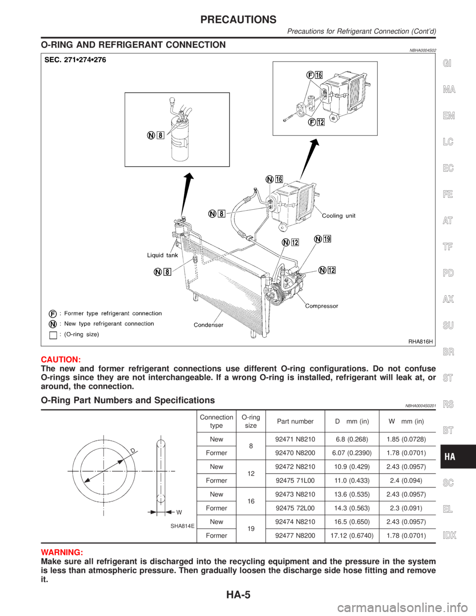
O-RING AND REFRIGERANT CONNECTIONNBHA0004S02
RHA816H
CAUTION:
The new and former refrigerant connections use different O-ring configurations. Do not confuse
O-rings since they are not interchangeable. If a wrong O-ring is installed, refrigerant will leak at, or
around, the connection.
O-Ring Part Numbers and SpecificationsNBHA0004S0201
SHA814E
Connection
typeO-ring
sizePart number D mm (in) W mm (in)
New
892471 N8210 6.8 (0.268) 1.85 (0.0728)
Former 92470 N8200 6.07 (0.2390) 1.78 (0.0701)
New
1292472 N8210 10.9 (0.429) 2.43 (0.0957)
Former 92475 71L00 11.0 (0.433) 2.4 (0.094)
New
1692473 N8210 13.6 (0.535) 2.43 (0.0957)
Former 92475 72L00 14.3 (0.563) 2.3 (0.091)
New
1992474 N8210 16.5 (0.650) 2.43 (0.0957)
Former 92477 N8200 17.12 (0.6740) 1.78 (0.0701)
WARNING:
Make sure all refrigerant is discharged into the recycling equipment and the pressure in the system
is less than atmospheric pressure. Then gradually loosen the discharge side hose fitting and remove
it.
GI
MA
EM
LC
EC
FE
AT
TF
PD
AX
SU
BR
ST
RS
BT
SC
EL
IDX
PRECAUTIONS
Precautions for Refrigerant Connection (Cont'd)
HA-5
Page 1806 of 2395
Precautions for Service EquipmentNBHA0006RECOVERY/RECYCLING EQUIPMENTNBHA0006S01Be certain to follow the manufacturers instructions for machine
operation and machine maintenance. Never introduce any refriger-
ant other than that specified into the machine.
ELECTRONIC LEAK DETECTORNBHA0006S02Be certain to follow the manufacturer's instructions for tester opera-
tion and tester maintenance.
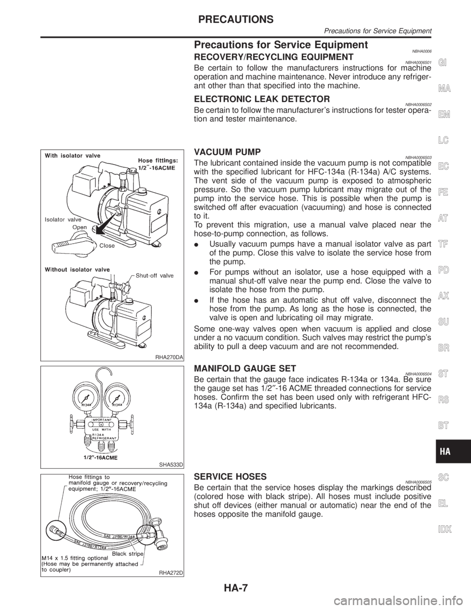
RHA270DA
VACUUM PUMPNBHA0006S03The lubricant contained inside the vacuum pump is not compatible
with the specified lubricant for HFC-134a (R-134a) A/C systems.
The vent side of the vacuum pump is exposed to atmospheric
pressure. So the vacuum pump lubricant may migrate out of the
pump into the service hose. This is possible when the pump is
switched off after evacuation (vacuuming) and hose is connected
to it.
To prevent this migration, use a manual valve placed near the
hose-to-pump connection, as follows.
IUsually vacuum pumps have a manual isolator valve as part
of the pump. Close this valve to isolate the service hose from
the pump.
IFor pumps without an isolator, use a hose equipped with a
manual shut-off valve near the pump end. Close the valve to
isolate the hose from the pump.
IIf the hose has an automatic shut off valve, disconnect the
hose from the pump. As long as the hose is connected, the
valve is open and lubricating oil may migrate.
Some one-way valves open when vacuum is applied and close
under a no vacuum condition. Such valves may restrict the pump's
ability to pull a deep vacuum and are not recommended.
SHA533D
MANIFOLD GAUGE SETNBHA0006S04Be certain that the gauge face indicates R-134a or 134a. Be sure
the gauge set has 1/2²-16 ACME threaded connections for service
hoses. Confirm the set has been used only with refrigerant HFC-
134a (R-134a) and specified lubricants.
RHA272D
SERVICE HOSESNBHA0006S05Be certain that the service hoses display the markings described
(colored hose with black stripe). All hoses must include positive
shut off devices (either manual or automatic) near the end of the
hoses opposite the manifold gauge.
GI
MA
EM
LC
EC
FE
AT
TF
PD
AX
SU
BR
ST
RS
BT
SC
EL
IDX
PRECAUTIONS
Precautions for Service Equipment
HA-7
Page 1808 of 2395
Wiring Diagrams and Trouble DiagnosesNBHA0007When you read wiring diagrams, refer to the following:
IGI-11, ªHOW TO READ WIRING DIAGRAMSº
IEL-10, ªWiring Diagram Ð POWER к for power distribution
circuit
When you perform trouble diagnoses, refer to the following:
IGI-34, ªHOW TO FOLLOW TROUBLE DIAGNOSESº
IGI-24, ªHOW TO PERFORM EFFICIENT DIAGNOSIS FOR
AN ELECTRICAL INCIDENTºGI
MA
EM
LC
EC
FE
AT
TF
PD
AX
SU
BR
ST
RS
BT
SC
EL
IDX
PRECAUTIONS
Wiring Diagrams and Trouble Diagnoses
HA-9
Page 1810 of 2395
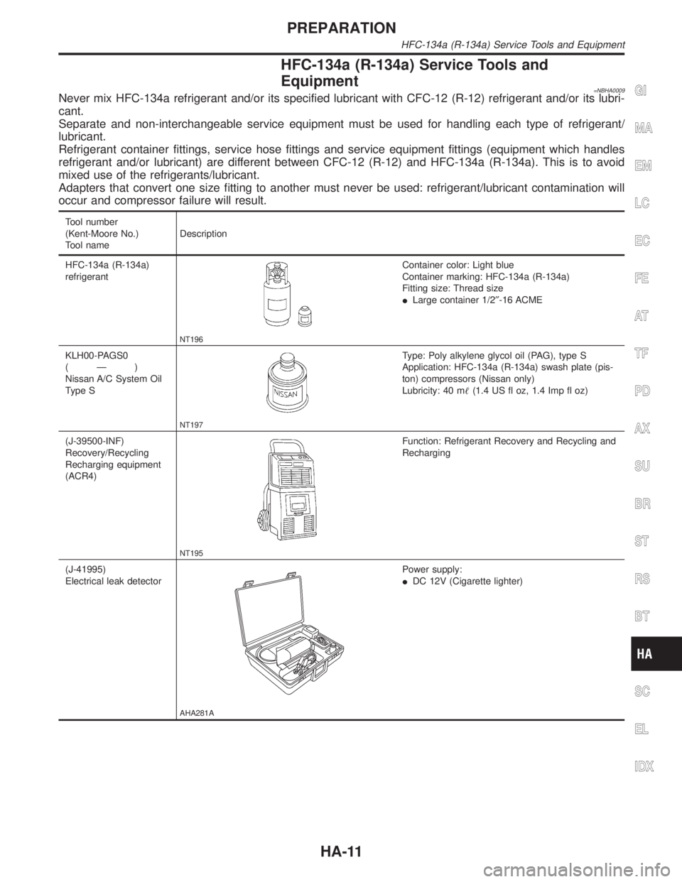
HFC-134a (R-134a) Service Tools and
Equipment
=NBHA0009Never mix HFC-134a refrigerant and/or its specified lubricant with CFC-12 (R-12) refrigerant and/or its lubri-
cant.
Separate and non-interchangeable service equipment must be used for handling each type of refrigerant/
lubricant.
Refrigerant container fittings, service hose fittings and service equipment fittings (equipment which handles
refrigerant and/or lubricant) are different between CFC-12 (R-12) and HFC-134a (R-134a). This is to avoid
mixed use of the refrigerants/lubricant.
Adapters that convert one size fitting to another must never be used: refrigerant/lubricant contamination will
occur and compressor failure will result.
Tool number
(Kent-Moore No.)
Tool nameDescription
HFC-134a (R-134a)
refrigerant
NT196
Container color: Light blue
Container marking: HFC-134a (R-134a)
Fitting size: Thread size
ILarge container 1/2²-16 ACME
KLH00-PAGS0
(Ð)
Nissan A/C System Oil
Type S
NT197
Type: Poly alkylene glycol oil (PAG), type S
Application: HFC-134a (R-134a) swash plate (pis-
ton) compressors (Nissan only)
Lubricity: 40 m(1.4 US fl oz, 1.4 Imp fl oz)
(J-39500-INF)
Recovery/Recycling
Recharging equipment
(ACR4)
NT195
Function: Refrigerant Recovery and Recycling and
Recharging
(J-41995)
Electrical leak detector
AHA281A
Power supply:
IDC 12V (Cigarette lighter)
GI
MA
EM
LC
EC
FE
AT
TF
PD
AX
SU
BR
ST
RS
BT
SC
EL
IDX
PREPARATION
HFC-134a (R-134a) Service Tools and Equipment
HA-11