AT-46 INFINITI QX4 2001 Factory Service Manual
[x] Cancel search | Manufacturer: INFINITI, Model Year: 2001, Model line: QX4, Model: INFINITI QX4 2001Pages: 2395, PDF Size: 43.2 MB
Page 13 of 2395

IBefore assembly, apply a coat of recommended ATF to all
parts. Apply petroleum jelly to protect O-rings and seals, or
hold bearings and washers in place during assembly. Do not
use grease.
IExtreme care should be taken to avoid damage to O-rings,
seals and gaskets when assembling.
IReplace ATF cooler if excessive foreign material is found in oil
pan or clogging strainer. Refer to ªATF COOLER SERVICEº,
AT-9.
IAfter overhaul, refill the transmission with new ATF.
IWhen the A/T drain plug is removed, only some of the fluid is
drained. Old A/T fluid will remain in torque converter and ATF
cooling system.
Always follow the procedures when changing A/T fluid. Refer
to MA-21, ªChanging A/T Fluidº.
Service Notice or PrecautionsNBAT0004FAIL-SAFENBAT0004S01The TCM has an electronic Fail-Safe (limp home mode). This allows the vehicle to be driven even if a major
electrical input/output device circuit is damaged.
Under Fail-Safe, the vehicle always runs in third gear, even with a shift lever position of ª1º, ª2º or ªDº. The
customer may complain of sluggish or poor acceleration.
When the ignition key is turned ªONº following Fail-Safe operation, O/D OFF indicator lamp blinks for about
8 seconds. (For ªTCM SELF-DIAGNOSTIC PROCEDURE (No Tools)º, refer to AT-46.)
Fail-Safe may occur without electrical circuit damage if the vehicle is driven under extreme conditions (such
as excessive wheel spin followed by sudden braking). To recover normal shift pattern, turn the ignition key
ªOFFº for 5 seconds, then ªONº.
The blinking of the O/D OFF indicator lamp for about 8 seconds will appear only once and be cleared. The
customer may resume normal driving conditions.
Always follow the ªWORK FLOWº (Refer to AT-57).
The SELF-DIAGNOSIS results will be as follows:
The first SELF-DIAGNOSIS will indicate damage to the vehicle speed sensor or the revolution sensor.
During the next SELF-DIAGNOSIS, performed after checking the sensor, no damages will be indicated.
TORQUE CONVERTER SERVICENBAT0004S04The torque converter should be replaced under any of the following conditions:
IExternal leaks in the hub weld area.
IConverter hub is scored or damaged.
IConverter pilot is broken, damaged or fits poorly into crankshaft.
ISteel particles are found after flushing the cooler and cooler lines.
IPump is damaged or steel particles are found in the converter.
IVehicle has TCC shudder and/or no TCC apply. Replace only after all hydraulic and electrical diagnoses
have been made. (Converter clutch material may be glazed.)
IConverter is contaminated with engine coolant containing antifreeze.
IInternal failure of stator roller clutch.
IHeavy clutch debris due to overheating (blue converter).
ISteel particles or clutch lining material found in fluid filter or on magnet when no internal parts in unit are
worn or damaged Ð indicates that lining material came from converter.
The torque converter should not be replaced if:
IThe fluid has an odor, is discolored, and there is no evidence of metal or clutch facing particles.
PRECAUTIONS
Precautions (Cont'd)
AT-8
Page 41 of 2395

SAT017K
HOW TO ERASE DTC (WITH GST)NBAT0016S041. If the ignition switch stays ªONº after repair work, be sure to turn ignition switch ªOFFº once. Wait at least
5 seconds and then turn it ªONº (engine stopped) again.
2. Perform ªOBD-II SELF-DIAGNOSTIC PROCEDURE (No Tools)º. Refer to AT-46. (The engine warm-up
step can be skipped when performing the diagnosis only to erase the DTC.)
3. Select Mode 4 with Generic Scan Tool (GST). For details, refer to EC-95, ªDESCRIPTIONº.
HOW TO ERASE DTC (NO TOOLS)NBAT0016S051. If the ignition switch stays ªONº after repair work, be sure to turn ignition switch ªOFFº once. Wait at least
5 seconds and then turn it ªONº (engine stopped) again.
2. Perform ªTCM SELF-DIAGNOSTIC PROCEDURE (No Tools)º. Refer to AT-46. (The engine warm-up step
can be skipped when performing the diagnosis only to erase the DTC.)
ON BOARD DIAGNOSTIC SYSTEM DESCRIPTION
OBD-II Diagnostic Trouble Code (DTC) (Cont'd)
AT-36
Page 51 of 2395

Diagnostic Procedure Without CONSULT-IINBAT0206OBD-II SELF-DIAGNOSTIC PROCEDURE (WITH GST)NBAT0206S01Refer to EC-95, ªDESCRIPTIONº.
OBD-II SELF-DIAGNOSTIC PROCEDURE (NO
TOOLS)
NBAT0206S02Refer to EC-74, ªDESCRIPTIONº.
SAT491J
SAT132K
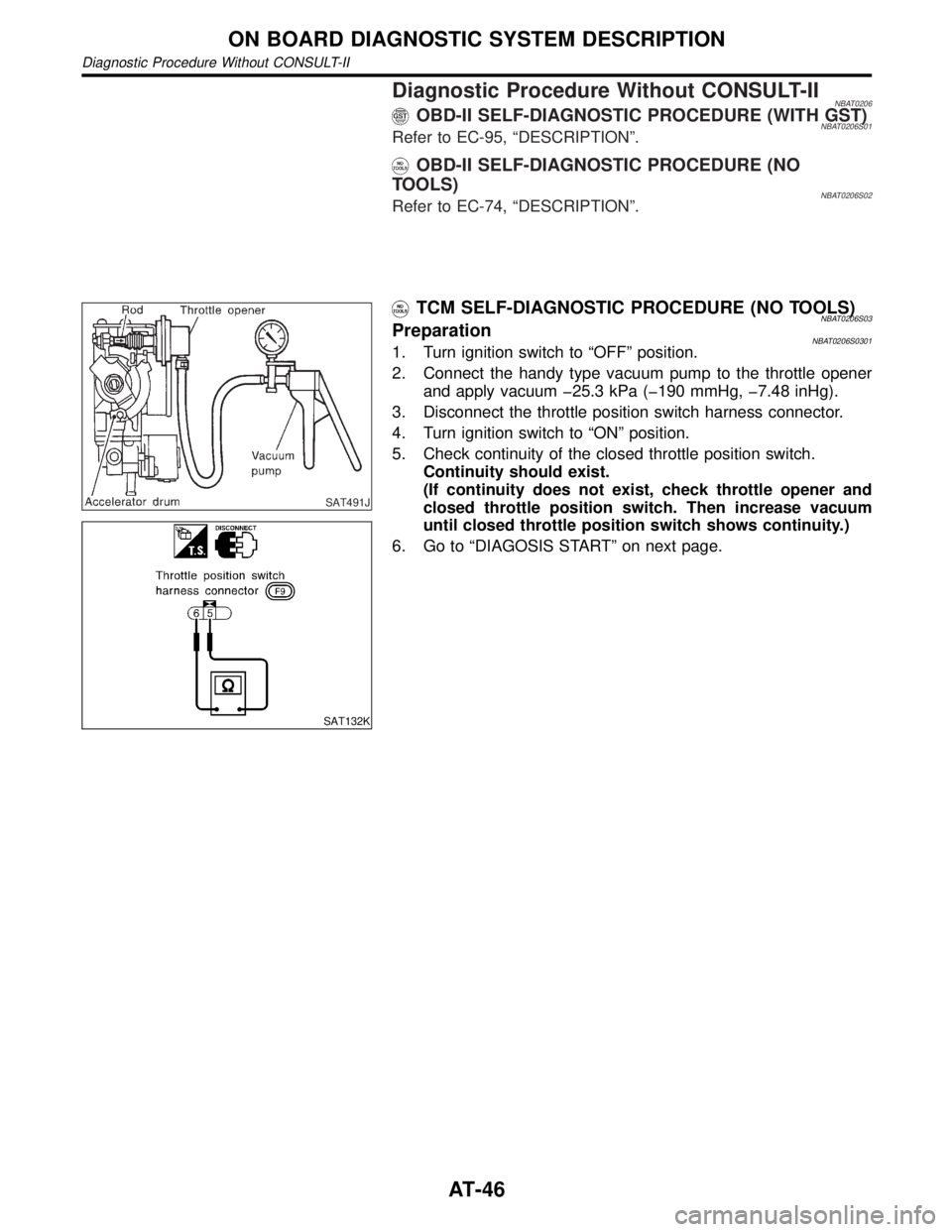
TCM SELF-DIAGNOSTIC PROCEDURE (NO TOOLS)NBAT0206S03PreparationNBAT0206S03011. Turn ignition switch to ªOFFº position.
2. Connect the handy type vacuum pump to the throttle opener
and apply vacuum þ25.3 kPa (þ190 mmHg, þ7.48 inHg).
3. Disconnect the throttle position switch harness connector.
4. Turn ignition switch to ªONº position.
5. Check continuity of the closed throttle position switch.
Continuity should exist.
(If continuity does not exist, check throttle opener and
closed throttle position switch. Then increase vacuum
until closed throttle position switch shows continuity.)
6. Go to ªDIAGOSIS STARTº on next page.
ON BOARD DIAGNOSTIC SYSTEM DESCRIPTION
Diagnostic Procedure Without CONSULT-II
AT-46
Page 70 of 2395

2 CHECK O/D OFF INDICATOR LAMP
Does O/D OFF indicator lamp flicker for about 8 seconds?
SAT133K
YesorNo
Ye s©Perform self-diagnosis. Refer to TCM SELF-DIAGNOSIS PROCEDURE (No Tools),
AT-46.
No©GO TO 3.
3 CHECK NG ITEM
1. Turn ignition switch to ªOFFº position.
2. Perform self-diagnosis and note NG items.
Refer to TCM SELF-DIAGNOSIS PROCEDURE (No Tools), AT-46.
©Go to ª2. Check at idleº, AT-66.
GI
MA
EM
LC
EC
FE
TF
PD
AX
SU
BR
ST
RS
BT
HA
SC
EL
IDX
TROUBLE DIAGNOSIS Ð BASIC INSPECTION
Road Test (Cont'd)
AT-65
Page 85 of 2395

7 CHECK ENGINE BRAKE
Does vehicle decelerate by engine brake?
SAT778B
YesorNo
Ye s©1. Stop vehicle.
2. Perform self-diagnosis. Refer to TCM SELF-DIAGNOSTIC PROCEDURE (No Tools),
AT-46.
No©Go to ª20. Vehicle Does Not Decelerate By Engine Brakeº, AT-256.
TROUBLE DIAGNOSIS Ð BASIC INSPECTION
Road Test (Cont'd)
AT-80
Page 98 of 2395

Terminal
No.Wire color Item ConditionJudgement
standard
(Approx.)
11 L/WShift solenoid
valve A
When shift solenoid valve A operates.
(When driving in ªD
1ºorªD4º.)Battery volt-
age
When shift solenoid valve A does not operate.
(When driving in ªD
2ºorªD3º.)0V
12 L/RShift solenoid
valve BWhen shift solenoid valve B operates.
(When driving in ªD
1ºorªD2º.)Battery volt-
age
When shift solenoid valve B does not operate.
(When driving in ªD
3ºorªD4º.)0V
13 GYO/D OFF indica-
tor lamp
When setting overdrive control switch in ªONº
position.Battery volt-
age
When setting overdrive control switch in
ªOFFº position.0V
14 Ð Ð Ð Ð
15 Ð Ð Ð Ð
16 OR/WClosed throttle
position switch
(in throttle posi-
tion switch)When releasing accelerator pedal after warm-
ing up engine.
Refer to ªPreparationº, ªTCM SELF-DIAG-
NOSTIC PROCEDURE (No Tools)º, AT-46.Battery volt-
age
When depressing accelerator pedal after
warming up engine.
Refer to ªPreparationº, ªTCM SELF-DIAG-
NOSTIC PROCEDURE (No Tools)º, AT-46.0V
17 OR/BWide open
throttle position
switch
(in throttle posi-
tion switch)When depressing accelerator pedal more than
half-way after warming up engine.Battery volt-
age
When releasing accelerator pedal after warm-
ing up engine.0V
18 B/YASCD cruise sig-
nal
When ASCD cruise is being performed.
(ªCRUISEº light comes on.)Battery volt-
age
When ASCD cruise is not being performed.
(ªCRUISEº light does not comes on.)0V
19 W/R Power source
Same as No. 10
20 L/BOverrun clutch
solenoid valve
When overrun clutch solenoid valve operates.Battery volt-
age
When overrun clutch solenoid valve does not
operate.0V
21 Ð Ð
ÐÐ
22 GYOverdrive control
switchWhen setting overdrive control switch in ªONº
positionBattery volt-
age
When setting overdrive control switch in
ªOFFº position0V
23 Ð Ð Ð Ð
GI
MA
EM
LC
EC
FE
TF
PD
AX
SU
BR
ST
RS
BT
HA
SC
EL
IDX
TROUBLE DIAGNOSIS Ð GENERAL DESCRIPTION
TCM Terminals and Reference Value (Cont'd)
AT-93
Page 181 of 2395

SAT142K
DescriptionNBAT0066IThrottle position sensor
The throttle position sensor detects the throttle valve position
and sends a signal to the TCM.
IThrottle position switch
Consists of a wide open throttle position switch and a closed
throttle position switch. The wide open position switch sends
a signal to the TCM when the throttle valve is open at least 1/2
of the full throttle position. The closed throttle position switch
sends a signal to the TCM when the throttle valve is fully
closed.
CONSULT-II REFERENCE VALUE IN DATA MONITOR
MODE
NBAT0066S02Remarks: Specification data are reference values.
Monitor item Condition Specification
Throttle position sensorFully-closed throttle Approximately 0.5V
Fully-open throttle Approximately 4V
TCM TERMINALS AND REFERENCE VALUENBAT0066S03Remarks: Specification data are reference values.
Terminal
No.Wire color Item ConditionJudgement
standard
(Approx.)
16 OR/WClosed throttle
position switch
(in throttle
position switch)
When releasing accelerator pedal after warm-
ing up engine.
[Refer to ªPreparationº, ªTCM SELF-DIAG-
NOSTIC PROCEDURE (No Tools)º, AT-46.]Battery volt-
age
When depressing accelerator pedal after
warming up engine.
[Refer to ªPreparationº, ªTCM SELF-DIAG-
NOSTIC PROCEDURE (No Tools)º, AT-46.]0V
17 OR/BWide open
throttle position
switch
(in throttle
position switch)When depressing accelerator pedal more than
half-way after warming up engine.Battery volt-
age
When releasing accelerator pedal after warm-
ing up engine.0V
32 P/BThrottle position
sensor
(Power source)Ignition switch ªONº. 4.5 - 5.5V
Ignition switch ªOFFº. 0V
41 PThrottle position
sensorWhen depressing accelerator pedal slowly
after warming up engine.
(Voltage rises gradually in response to throttle
position.)Fully-closed
throttle:
0.5 - 0.7V
Fully-open
throttle:
4V
42 BThrottle position
sensor
(Ground)ÐÐ
DTC P1705 THROTTLE POSITION SENSOR
Description
AT-176
Page 182 of 2395

ON BOARD DIAGNOSIS LOGICNBAT0066S04
Diagnostic trouble code Malfunction is detected when ... Check item (Possible cause)
: TP SEN/CIRC A/T
TCM receives an excessively low or high
voltage from the sensor.IHarness or connectors
(The solenoid circuit is open or shorted.)
IThrottle position sensor
IThrottle position switch
: P1705
SAT014K
SAT971J
SAT014K
SAT020K
DIAGNOSTIC TROUBLE CODE (DTC) CONFIRMATION
PROCEDURE
NBAT0066S01CAUTION:
Always drive vehicle at a safe speed.
NOTE:
If ªDIAGNOSTIC TROUBLE CODE CONFIRMATION PROCE-
DUREº has been previously conducted, always turn ignition
switch ªOFFº and wait at least 5 seconds before conducting
the next test.
After the repair, perform the following procedure to confirm the
malfunction is eliminated.
With CONSULT-II
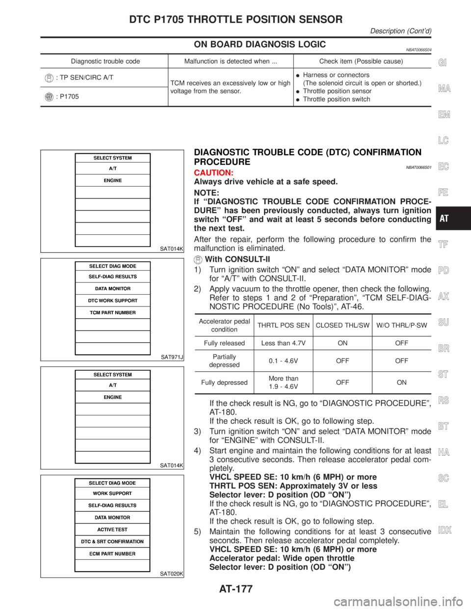
1) Turn ignition switch ªONº and select ªDATA MONITORº mode
for ªA/Tº with CONSULT-II.
2) Apply vacuum to the throttle opener, then check the following.
Refer to steps 1 and 2 of ªPreparationº, ªTCM SELF-DIAG-
NOSTIC PROCEDURE (No Tools)º, AT-46.
Accelerator pedal
conditionTHRTL POS SEN CLOSED THL/SW W/O THRL/P´SW
Fully released Less than 4.7V ON OFF
Partially
depressed0.1 - 4.6V OFF OFF
Fully depressedMore than
1.9 - 4.6VOFF ON
If the check result is NG, go to ªDIAGNOSTIC PROCEDUREº,
AT-180.
If the check result is OK, go to following step.
3) Turn ignition switch ªONº and select ªDATA MONITORº mode
for ªENGINEº with CONSULT-II.
4) Start engine and maintain the following conditions for at least
3 consecutive seconds. Then release accelerator pedal com-
pletely.
VHCL SPEED SE: 10 km/h (6 MPH) or more
THRTL POS SEN: Approximately 3V or less
Selector lever: D position (OD ªONº)
If the check result is NG, go to ªDIAGNOSTIC PROCEDUREº,
AT-180.
If the check result is OK, go to following step.
5) Maintain the following conditions for at least 3 consecutive
seconds. Then release accelerator pedal completely.
VHCL SPEED SE: 10 km/h (6 MPH) or more
Accelerator pedal: Wide open throttle
Selector lever: D position (OD ªONº)
GI
MA
EM
LC
EC
FE
TF
PD
AX
SU
BR
ST
RS
BT
HA
SC
EL
IDX
DTC P1705 THROTTLE POSITION SENSOR
Description (Cont'd)
AT-177
Page 187 of 2395

3 CHECK THROTTLE POSITION SWITCH CIRCUIT (With CONSULT-II)
With CONSULT-II
1. Turn ignition switch to ªONº position.
(Do not start engine.)
2. Select ªTCM INPUT SIGNALSº in ªDATA MONITORº mode for ªA/Tº with CONSULT-II.
3. Apply vacuum to the throttle opener, then check the following. Refer to steps 1 and 2 of ªPreparationº, ªTCM SELF-
DIAGNOSTIC PROCEDURE (No Tools)º, AT-46.
4. Read out ªCLOSED THL/SWº and ªW/O THRL/P-SWº depressing and releasing accelerator pedal.
Check the signal of throttle position switch is indicated properly.
MTBL0011
SAT646J
OK or NG
OK©GO TO 6.
NG©GO TO 4.
4 DETECT MALFUNCTIONING ITEM
Check the following items:
IThrottle position switch
Refer to ªComponent Inspectionº, AT-184.
IHarness for short or open between ignition switch and throttle position switch (Main harness)
IHarness for short or open between throttle position switch and TCM (Main harness)
OK or NG
OK©GO TO 6.
NG©Repair or replace damaged parts.
DTC P1705 THROTTLE POSITION SENSOR
Diagnostic Procedure (Cont'd)
AT-182
Page 188 of 2395

5 CHECK THROTTLE POSITION SWITCH CIRCUIT (Without CONSULT-II)
Without CONSULT-II
1. Turn ignition switch to ªONº position.
(Do not start engine.)
2. Check voltage between TCM terminals 16, 17 and ground while depressing, and releasing accelerator pedal slowly.
(after warming up engine)
[Refer to ªPreparationº, ªTCM SELF-DIAGNOSTIC PROCEDURE (No Tools)º, AT-46.]
MTBL0519
SAT526J
OK or NG
OK©GO TO 6.
NG©GO TO 4.
6 CHECK DTC
Perform Diagnostic Trouble Code (DTC) confirmation procedure, AT-177.
OK or NG
OK©INSPECTION END
NG©GO TO 7.
7 CHECK TCM INSPECTION
1. Perform TCM input/output signal inspection.
2. If NG, recheck TCM pin terminals for damage or loose connection with harness connector.
OK or NG
OK©INSPECTION END
NG©Repair or replace damaged parts.
GI
MA
EM
LC
EC
FE
TF
PD
AX
SU
BR
ST
RS
BT
HA
SC
EL
IDX
DTC P1705 THROTTLE POSITION SENSOR
Diagnostic Procedure (Cont'd)
AT-183