Ignition harness INFINITI QX4 2001 Factory Service Manual
[x] Cancel search | Manufacturer: INFINITI, Model Year: 2001, Model line: QX4, Model: INFINITI QX4 2001Pages: 2395, PDF Size: 43.2 MB
Page 11 of 2395

Precautions for Supplemental Restraint System
(SRS) ªAIR BAGº and ªSEAT BELT
PRE-TENSIONERº
NBAT0001The supplemental Restraint System such as ªAIR BAGº and ªSEAT BELT PRE-TENSIONERº used along with
a seat belt, helps to reduce the risk or severity of injury to the driver and front passenger for certain types of
collision. The SRS system composition which is available to INFINITI QX4 is as follows:
IFor a frontal collision
The Supplemental Restraint System consists of driver air bag module (located in the center of the steer-
ing wheel), front passenger air bag module (located on the instrument panel on passenger side), seat belt
pre-tensioners, a diagnosis sensor unit, warning lamp, wiring harness and spiral cable.
IFor a side collision
The Supplemental Restraint System consists of front side air bag module (located in the outer side of front
seat), satellite sensor, diagnosis sensor unit (one of components of air bags for a frontal collision), wiring
harness, warning lamp (one of components of air bags for a frontal collision).
Information necessary to service the system safely is included in theRS sectionof this Service Manual.
WARNING:
ITo avoid rendering the SRS inoperative, which could increase the risk of personal injury or death
in the event of a collision which would result in air bag inflation, all maintenance must be performed
by an authorized INFINITI dealer.
IImproper maintenance, including incorrect removal and installation of the SRS, can lead to per-
sonal injury caused by unintentional activation of the system. For removal of Spiral Cable and Air
Bag Module, see the RS section.
IDo not use electrical test equipment on any circuit related to the SRS unless instructed to in this
Service Manual. Spiral cable and wiring harnesses covered with yellow insulation tape either just
before the harness connectors or for the complete harness are related to the SRS.
Precautions for On Board Diagnostic (OBD)
System of A/T and Engine
NBAT0002The ECM has an on board diagnostic system. It will light up the malfunction indicator lamp (MIL) to warn the
driver of a malfunction causing emission deterioration.
CAUTION:
IBe sure to turn the ignition switch ªOFFº and disconnect the negative battery terminal before any
repair or inspection work. The open/short circuit of related switches, sensors, solenoid valves, etc.
will cause the MIL to light up.
IBe sure to connect and lock the connectors securely after work. A loose (unlocked) connector will
cause the MIL to light up due to an open circuit. (Be sure the connector is free from water, grease,
dirt, bent terminals, etc.)
IBe sure to route and secure the harnesses properly after work. Interference of the harness with a
bracket, etc. may cause the MIL to light up due to a short circuit.
IBe sure to connect rubber tubes properly after work. A misconnected or disconnected rubber tube
may cause the MIL to light up due to a malfunction of the EGR system or fuel injection system,
etc.
IBe sure to erase the unnecessary malfunction information (repairs completed) from the TCM and
ECM before returning the vehicle to the customer.
SEF289H
PrecautionsNBAT0003IBefore connecting or disconnecting the TCM harness
connector, turn ignition switch ªOFFº and disconnect
negative battery terminal. Failure to do so may damage
the TCM. Because battery voltage is applied to TCM even
if ignition switch is turned ªOFFº.
PRECAUTIONS
Precautions for Supplemental Restraint System (SRS) ªAIR BAGº and ªSEAT BELT PRE-TENSIONERº
AT-6
Page 51 of 2395

Diagnostic Procedure Without CONSULT-IINBAT0206OBD-II SELF-DIAGNOSTIC PROCEDURE (WITH GST)NBAT0206S01Refer to EC-95, ªDESCRIPTIONº.
OBD-II SELF-DIAGNOSTIC PROCEDURE (NO
TOOLS)
NBAT0206S02Refer to EC-74, ªDESCRIPTIONº.
SAT491J
SAT132K
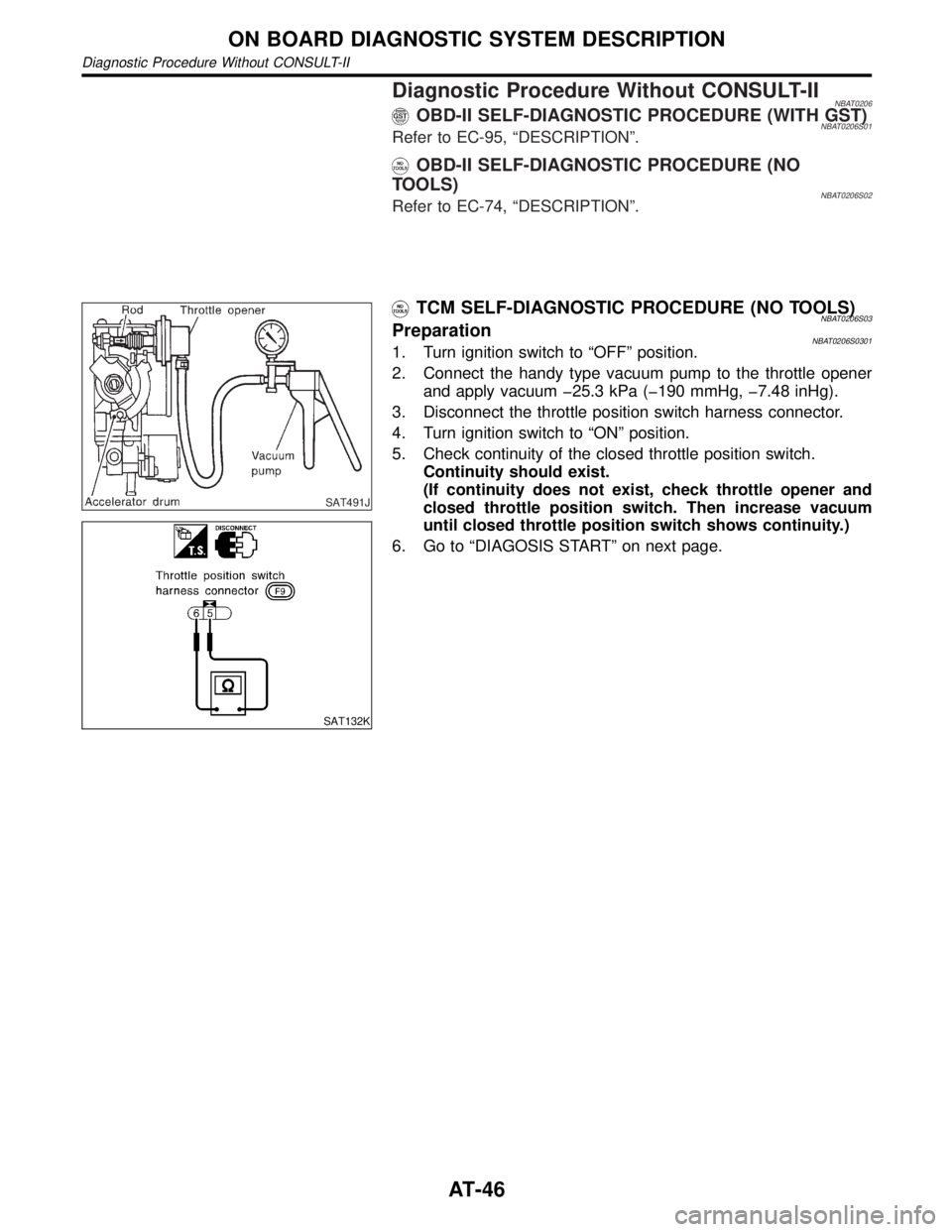
TCM SELF-DIAGNOSTIC PROCEDURE (NO TOOLS)NBAT0206S03PreparationNBAT0206S03011. Turn ignition switch to ªOFFº position.
2. Connect the handy type vacuum pump to the throttle opener
and apply vacuum þ25.3 kPa (þ190 mmHg, þ7.48 inHg).
3. Disconnect the throttle position switch harness connector.
4. Turn ignition switch to ªONº position.
5. Check continuity of the closed throttle position switch.
Continuity should exist.
(If continuity does not exist, check throttle opener and
closed throttle position switch. Then increase vacuum
until closed throttle position switch shows continuity.)
6. Go to ªDIAGOSIS STARTº on next page.
ON BOARD DIAGNOSTIC SYSTEM DESCRIPTION
Diagnostic Procedure Without CONSULT-II
AT-46
Page 97 of 2395

AAT475A
TCM Terminals and Reference Value=NBAT0027PREPARATIONNBAT0027S01IMeasure voltage between each terminal and terminal 25 or 48
by following ªTCM INSPECTION TABLEº.
SAT217JB
TCM HARNESS CONNECTOR TERMINAL LAYOUTNBAT0027S02TCM INSPECTION TABLENBAT0027S03(Data are reference values.)
Terminal
No.Wire color Item ConditionJudgement
standard
(Approx.)
1GYLine pressure
solenoid valve
When releasing accelerator pedal after warm-
ing up engine.1.5 - 3.0V
When depressing accelerator pedal fully after
warming up engine.0V
2 BR/YLine pressure
solenoid valve
(with dropping
resistor)When releasing accelerator pedal after warm-
ing up engine.5 - 14V
When depressing accelerator pedal fully after
warming up engine.0V
3 G/ORTorque converter
clutch solenoid
valve
When A/T performs lock-up. 8 - 15V
When A/T does not perform lock- up. 0V
4Ð Ð
ÐÐ
5Ð Ð Ð Ð
6Ð Ð Ð Ð
7Ð Ð Ð Ð
8Ð Ð Ð Ð
9Ð Ð Ð Ð
10 W/R Power sourceWhen turning ignition switch to ªONº.Battery volt-
age
When turning ignition switch to ªOFFº. 0V
TROUBLE DIAGNOSIS Ð GENERAL DESCRIPTION
TCM Terminals and Reference Value
AT-92
Page 103 of 2395

2 CHECK TCM POWER SOURCE STEP 2
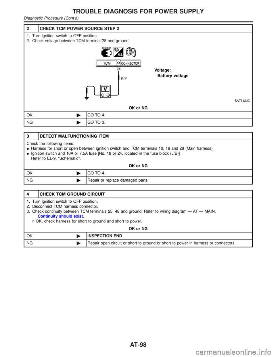
1. Turn ignition switch to OFF position.
2. Check voltage between TCM terminal 28 and ground.
SAT612JC
OK or NG
OK©GO TO 4.
NG©GO TO 3.
3 DETECT MALFUNCTIONING ITEM
Check the following items:
IHarness for short or open between ignition switch and TCM terminals 10, 19 and 28 (Main harness)
IIgnition switch and 10A or 7.5A fuse [No. 18 or 24, located in the fuse block (J/B)]
Refer to EL-9, ªSchematicº.
OK or NG
OK©GO TO 4.
NG©Repair or replace damaged parts.
4 CHECK TCM GROUND CIRCUIT
1. Turn ignition switch to OFF position.
2. Disconnect TCM harness connector.
3. Check continuity between TCM terminals 25, 48 and ground. Refer to wiring diagram Ð AT Ð MAIN.
Continuity should exist.
If OK, check harness for short to ground and short to power.
OK or NG
OK©INSPECTION END
NG©Repair open circuit or short to ground or short to power in harness or connectors.
TROUBLE DIAGNOSIS FOR POWER SUPPLY
Diagnostic Procedure (Cont'd)
AT-98
Page 108 of 2395

3 DETECT MALFUNCTIONING ITEM
Check the following items:
IPNP switch
Refer to ªComponent Inspectionº, AT-103.
IHarness for short or open between ignition switch and PNP switch (Main harness)
IHarness for short or open between PNP switch and TCM (Main harness)
IDiode (P, N position)
IIgnition switch and 10A fuse [No. 18, located in the fuse block (J/B)]
Refer to EL-9, ªSchematicº.
OK or NG
OK©GO TO 4.
NG©Repair or replace damaged parts.
4 CHECK DTC
Perform Diagnostic Trouble Code (DTC) confirmation procedure, AT-100.
OK or NG
OK©INSPECTION END
NG©GO TO 5.
5 CHECK TCM INSPECTION
1. Perform TCM input/output signal inspection.
2. If NG, recheck TCM pin terminals for damage or loose connection with harness connector.
OK or NG
OK©INSPECTION END
NG©Repair or replace damaged parts.
SAT517GB
SAT843BG
Component InspectionNBAT0030PARK/NEUTRAL POSITION SWITCHNBAT0030S021. Check continuity between terminals 1 and 2 and between ter-
minals 3 and 4, 5, 6, 7, 8, 9 while moving manual shaft through
each position.
Lever position Terminal No.
P 1-2 3-4
R 3-5
N 1-2 3-6
D 3-7
2 3-8
1 3-9
GI
MA
EM
LC
EC
FE
TF
PD
AX
SU
BR
ST
RS
BT
HA
SC
EL
IDX
DTC P0705 PARK/NEUTRAL POSITION SWITCH
Diagnostic Procedure (Cont'd)
AT-103
Page 114 of 2395

4 CHECK A/T FLUID TEMPERATURE SENSOR WITH TERMINAL CORD ASSEMBLY
1. Turn ignition switch to ªOFFº position.
2. Disconnect terminal cord assembly connector on the right side of transfer assmebly.
3. Check resistance between terminals 8 and 9 when A/T is cold [20ÉC (68ÉF)].
SAT697I
Is resistance approx. 2.5 kW?
Ye s©GO TO 7.
No©GO TO 5.
5 DETECT MALFUNCTIONING ITEM
1. Remove oil pan.
2. Check the following items:
IA/T fluid temperature sensor
Refer to ªComponent Inspectionº, AT-110.
IHarness of terminal cord assembly for short or open
OK or NG
OK©GO TO 7.
NG©Repair or replace damaged parts.
6 CHECK INPUT SIGNAL OF A/T FLUID TEMPERATURE SENSOR (WITHOUT CONSULT-II)
Without CONSULT-II
1. Start engine.
2. Check voltage between TCM terminal 47 and ground while warming up A/T.
Voltage:
Cold [20ÉC (68ÉF)]®Hot [80ÉC (176ÉF)]:
Approximately 1.5V®0.5V
SAT518J
OK or NG
OK©GO TO 4.
NG©GO TO 3.
GI
MA
EM
LC
EC
FE
TF
PD
AX
SU
BR
ST
RS
BT
HA
SC
EL
IDX
DTC P0710 A/T FLUID TEMPERATURE SENSOR CIRCUIT
Diagnostic Procedure (Cont'd)
AT-109
Page 121 of 2395

DescriptionNBAT0037The engine speed signal is sent from the ECM to the TCM.
TCM TERMINALS AND REFERENCE VALUENBAT0037S02Remarks: Specification data are reference values.
Terminal
No.Wire color Item ConditionJudgement
standard
(Approx.)
39 W/BEngine speed sig-
nal
Refer to EC-127, ªECM INSPECTION
TABLEº.Ð
ON BOARD DIAGNOSIS LOGICNBAT0037S03
Diagnostic trouble code Malfunction is detected when ... Check item (Possible cause)
: ENGINE SPEED SIG
TCM does not receive the proper voltage
signal from ECM.IHarness or connectors
(The sensor circuit is open or shorted.)
: P0725
SAT014K
SAT020K
DIAGNOSTIC TROUBLE CODE (DTC) CONFIRMATION
PROCEDURE
NBAT0037S01CAUTION:
Always drive vehicle at a safe speed.
NOTE:
If ªDIAGNOSTIC TROUBLE CODE CONFIRMATION PROCE-
DUREº has been previously conducted, always turn ignition
switch ªOFFº and wait at least 5 seconds before conducting
the next test.
After the repair, perform the following procedure to confirm the
malfunction is eliminated.
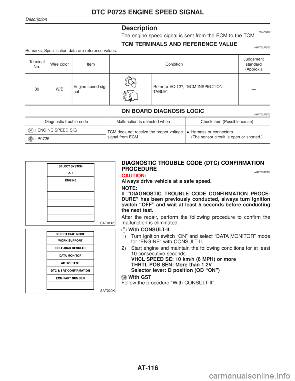
With CONSULT-II
1) Turn ignition switch ªONº and select ªDATA MONITORº mode
for ªENGINEº with CONSULT-II.
2) Start engine and maintain the following conditions for at least
10 consecutive seconds.
VHCL SPEED SE: 10 km/h (6 MPH) or more
THRTL POS SEN: More than 1.2V
Selector lever: D position (OD ªONº)
With GST
Follow the procedure ªWith CONSULT-IIº.
DTC P0725 ENGINE SPEED SIGNAL
Description
AT-116
Page 123 of 2395

Diagnostic ProcedureNBAT0038
1 CHECK DTC WITH ECM
ICheck P code with CONSULT-II.
Turn ignition switch ªONº and select ªSELF-DIAG RESULTSº mode for ªENGINEº with CONSULT-II.
Refer to EC-74, ªDESCRIPTIONº.
OK or NG
OK (With CONSULT-II)©GO TO 2.
OK (Without CONSULT-
II)©GO TO 4.
NG©Check ignition signal circuit for engine control. Refer to EC-499, ªComponent Descrip-
tionº.
2 CHECK INPUT SIGNAL (WITH CONSULT-II)
With CONSULT-II
1. Start engine.
2. Select ªTCM INPUT SIGNALSº in ªDATA MONITORº mode for ªA/Tº with CONSULT-II.
3. Read out the value of ªENGINE SPEEDº.
Check engine speed changes according to throttle position.
SAT645J
Refer toEC-127, ªECM INSPECTION TABLEº.
Ye s©GO TO 5.
No©GO TO 3.
3 DETECT MALFUNCTIONING ITEM
Check the following items:
IHarness for short or open between TCM and ECM
IResistor
IIgnition coil
Refer to EC-499, ªComponent Descriptionº.
OK or NG
OK©GO TO 5.
NG©Repair or replace damaged parts.
DTC P0725 ENGINE SPEED SIGNAL
Diagnostic Procedure
AT-118
Page 156 of 2395

Diagnostic ProcedureNBAT0052
1 CHECK VALVE RESISTANCE
1. Turn ignition switch to ªOFFº position.
2. Disconnect terminal cord assembly connector on the right side of transfer assembly.
3. Check resistance between terminal 7 and ground.
SAT156J
Is resistance approx. 10 - 20W?
Ye s©GO TO 3.
No©GO TO 2.
2 CHECK VALVE OPERATION
1. Remove oil pan. Refer to AT-273.
2. Check the following items:
ITorque converter clutch solenoid valve
Refer to ªComponent Inspectionº, AT-152.
IHarness of terminal cord assembly for short or open
OK or NG
OK©GO TO 3.
NG©Repair open circuit or short to ground or short to power in harness or connectors.
3 CHECK RESISTANCE
1. Turn ignition switch to ªOFFº position.
2. Disconnect TCM harness connector.
3. Check resistance between terminal 7 and TCM harness connector terminal 3. Refer to wiring diagram Ð AT Ð TCV.
Continuity should exist.
If OK, check harness for short to ground and short to power.
4. Reinstall any part removed.
OK or NG
OK©GO TO 4.
NG©Repair open circuit or short to ground or short to power in harness or connectors.
4 CHECK DTC
Perform Diagnostic Trouble Code (DTC) confirmation procedure, AT-149.
OK or NG
OK©INSPECTION END
NG©GO TO 5.
GI
MA
EM
LC
EC
FE
TF
PD
AX
SU
BR
ST
RS
BT
HA
SC
EL
IDX
DTC P0740 TORQUE CONVERTER CLUTCH SOLENOID VALVE
Diagnostic Procedure
AT-151
Page 170 of 2395

Diagnostic ProcedureNBAT0058
1 CHECK VALVE RESISTANCE
1. Turn ignition switch to ªOFFº position.
2. Disconnect terminal cord assembly connector on the right side of transfer assembly.
3. Check resistance between terminal 6 and ground.
SAT162J
Is resistance approx. 2.5 - 5W?
Ye s©GO TO 3.
No©GO TO 2.
2 CHECK VALVE OPERATION
1. Remove control valve assembly.
Refer to AT-273.
2. Check the following items:
ILine pressure solenoid valve
Refer to ªComponent Inspectionº, AT-167.
IHarness of terminal cord assembly for short or open
OK or NG
OK©GO TO 3.
NG©Repair or replace damaged parts.
GI
MA
EM
LC
EC
FE
TF
PD
AX
SU
BR
ST
RS
BT
HA
SC
EL
IDX
DTC P0745 LINE PRESSURE SOLENOID VALVE
Diagnostic Procedure
AT-165