clock INFINITI QX4 2001 Factory Service Manual
[x] Cancel search | Manufacturer: INFINITI, Model Year: 2001, Model line: QX4, Model: INFINITI QX4 2001Pages: 2395, PDF Size: 43.2 MB
Page 25 of 2395

ªD1º and ª21º Positions=NBAT0012S0402
Forward one-way clutch
Forward clutch
Low one-way clutchRear internal gear is locked to rotate counterclockwise because of the functioning of
these three clutches. (Start-up at D
1)
Overrun clutch
engagement conditions
(Engine brake)D
1: Overdrive control switch in ªOFFº
Throttle opening less than 3/16
2
1: Throttle opening less than 3/16
At D
1and 21positions, engine brake is not activated due to free turning of low one-way
clutch.
SAT096J
OVERALL SYSTEM
Shift Mechanism (Cont'd)
AT-20
Page 291 of 2395
NBAT0111
SAT018B
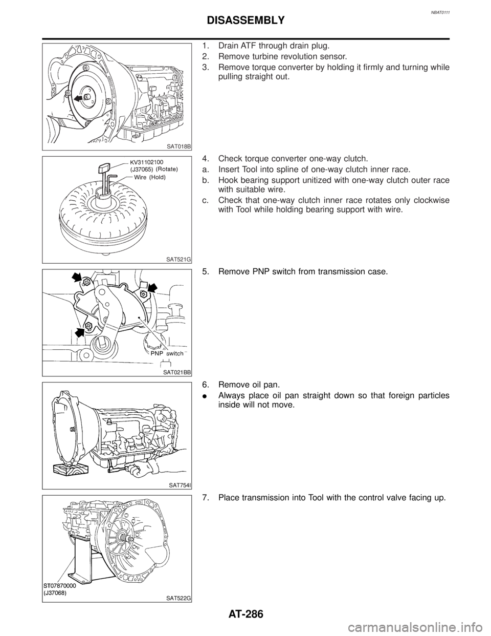
1. Drain ATF through drain plug.
2. Remove turbine revolution sensor.
3. Remove torque converter by holding it firmly and turning while
pulling straight out.
SAT521G
4. Check torque converter one-way clutch.
a. Insert Tool into spline of one-way clutch inner race.
b. Hook bearing support unitized with one-way clutch outer race
with suitable wire.
c. Check that one-way clutch inner race rotates only clockwise
with Tool while holding bearing support with wire.
SAT021BB
5. Remove PNP switch from transmission case.
SAT754I
6. Remove oil pan.
IAlways place oil pan straight down so that foreign particles
inside will not move.
SAT522G
7. Place transmission into Tool with the control valve facing up.
DISASSEMBLY
AT-286
Page 338 of 2395

SAT905A
8. After installing, check to assure that forward clutch hub rotates
clockwise.
Band Servo Piston Assembly
COMPONENTSNBAT0148
SAT161K
SAT909A
DISASSEMBLYNBAT01491. Block one oil hole in OD servo piston retainer and the center
hole in OD band servo piston.
2. Apply compressed air to the other oil hole in piston retainer to
remove OD band servo piston from retainer.
3. Remove D-ring from OD band servo piston.
SAT910A
4. Remove band servo piston assembly from servo piston
retainer by pushing it forward.
GI
MA
EM
LC
EC
FE
TF
PD
AX
SU
BR
ST
RS
BT
HA
SC
EL
IDX
REPAIR FOR COMPONENT PARTS
Rear Internal Gear and Forward Clutch Hub (Cont'd)
AT-333
Page 346 of 2395
SAT940A
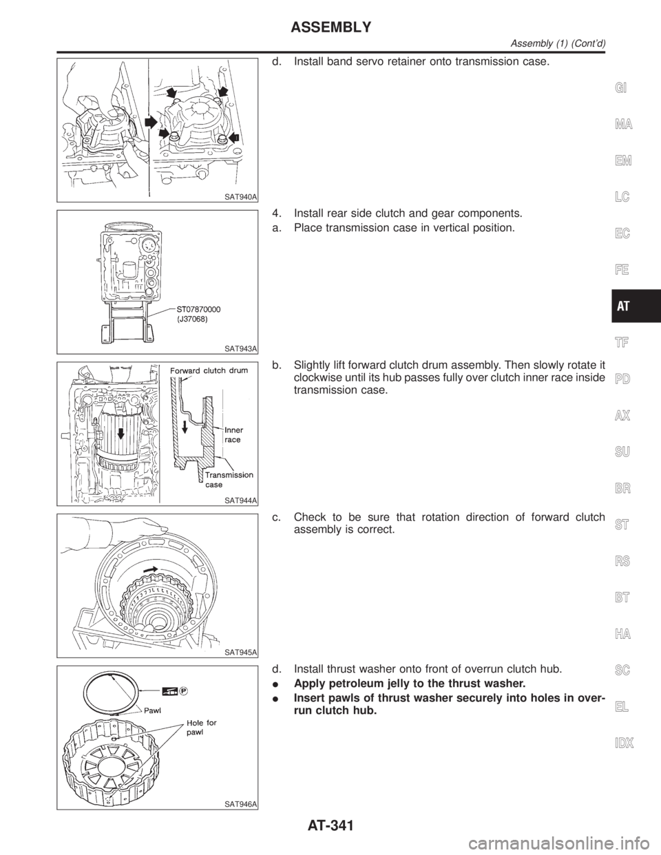
d. Install band servo retainer onto transmission case.
SAT943A
4. Install rear side clutch and gear components.
a. Place transmission case in vertical position.
SAT944A
b. Slightly lift forward clutch drum assembly. Then slowly rotate it
clockwise until its hub passes fully over clutch inner race inside
transmission case.
SAT945A
c. Check to be sure that rotation direction of forward clutch
assembly is correct.
SAT946A
d. Install thrust washer onto front of overrun clutch hub.
IApply petroleum jelly to the thrust washer.
IInsert pawls of thrust washer securely into holes in over-
run clutch hub.
GI
MA
EM
LC
EC
FE
TF
PD
AX
SU
BR
ST
RS
BT
HA
SC
EL
IDX
ASSEMBLY
Assembly (1) (Cont'd)
AT-341
Page 351 of 2395

SAT967A
b. Make sure needle bearing is on front of front planetary carrier.
IApply petroleum jelly to needle bearing.
c. Make sure needle bearing is on rear of front planetary carrier.
IApply petroleum jelly to bearing.
IPay attention to its direction Ð Black side goes to front.
SAT969A
d. While rotating forward clutch drum clockwise, install front plan-
etary carrier on forward clutch drum.
SAT970A
ICheck that portion A of front planetary carrier protrudes
approximately 2 mm (0.08 in) beyond portion B of forward
clutch assembly.
SAT971A
e. Make sure bearing races are on front and rear of clutch pack.
IApply petroleum jelly to bearing races.
ISecurely engage pawls of bearing races with holes in
clutch pack.
SAT973A
f. Install clutch pack into transmission case.
ASSEMBLY
Assembly (1) (Cont'd)
AT-346
Page 477 of 2395

Work FlowNBBT0024
SBT842
CUSTOMER INTERVIEWNBBT0024S01Interview the customer, if possible, to determine the conditions that exist when the noise occurs. Use the
Diagnostic Worksheet during the interview to document the facts and conditions when the noise occurs and
any customer's comments; refer to BT-8. This information is necessary to duplicate the conditions that exist
when the noise occurs.
IThe customer may not be able to provide a detailed description or the location of the noise. Attempt to
obtain all the facts and conditions that exist when the noise occurs (or does not occur).
IIf there is more than one noise in the vehicle, be sure to diagnose and repair the noise that the customer
is concerned about. This can be accomplished by test driving the vehicle with the customer.
IAfter identifying the type of noise, isolate the noise in terms of its characteristics. The noise characteris-
tics are provided so the customer, service adviser and technician are all speaking the same language when
defining the noise.
ISqueak Ð (Like tennis shoes on a clean floor)
Squeak characteristics include the light contact/fast movement/brought on by road conditions/hard sur-
faces = higher pitch noise/softer surfaces = lower pitch noises/edge to surface = chirping
ICreak Ð (Like walking on an old wooden floor)
Creak characteristics include firm contact/slow movement/twisting with a rotational movement/pitch depen-
dent on materials/often brought on by activity.
IRattle Ð (Like shaking a baby rattle)
Rattle characteristics include the fast repeated contact/vibration or similar movement/loose parts/missing
clip or fastener/incorrect clearance.
IKnock Ð (Like a knock on a door)
Knock characteristics include hollow sounding/sometimes repeating/often brought on by driver action.
ITick Ð (Like a clock second hand)
Tick characteristics include gentle contacting of light materials/loose components/can be caused by driver
action or road conditions.
IThump Ð (Heavy, muffled knock noise)
Thump characteristics include softer knock/dead sound often brought on by activity.
IBuzz Ð (Like a bumble bee)
Buzz characteristics include high frequency rattle/firm contact.
IOften the degree of acceptable noise level will vary depending upon the person. A noise that you may judge
as acceptable may be very irritating to the customer.
IWeather conditions, especially humidity and temperature, may have a great effect on noise level.
SQUEAK AND RATTLE TROUBLE DIAGNOSES
Work Flow
BT-4
Page 641 of 2395
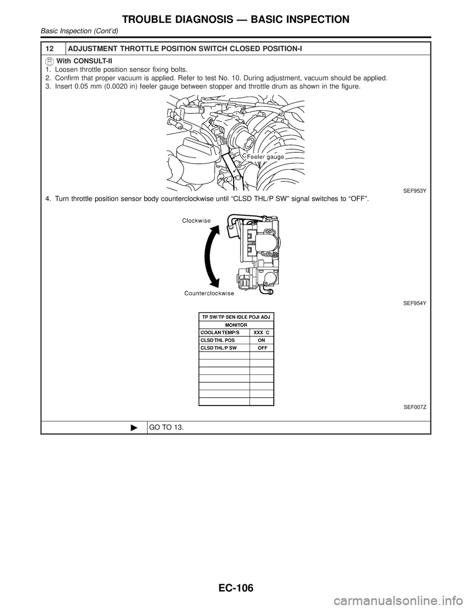
12 ADJUSTMENT THROTTLE POSITION SWITCH CLOSED POSITION-I
With CONSULT-II
1. Loosen throttle position sensor fixing bolts.
2. Confirm that proper vacuum is applied. Refer to test No. 10. During adjustment, vacuum should be applied.
3. Insert 0.05 mm (0.0020 in) feeler gauge between stopper and throttle drum as shown in the figure.
SEF953Y
4. Turn throttle position sensor body counterclockwise until ªCLSD THL/P SWº signal switches to ªOFFº.
SEF954Y
SEF007Z
©GO TO 13.
TROUBLE DIAGNOSIS Ð BASIC INSPECTION
Basic Inspection (Cont'd)
EC-106
Page 642 of 2395
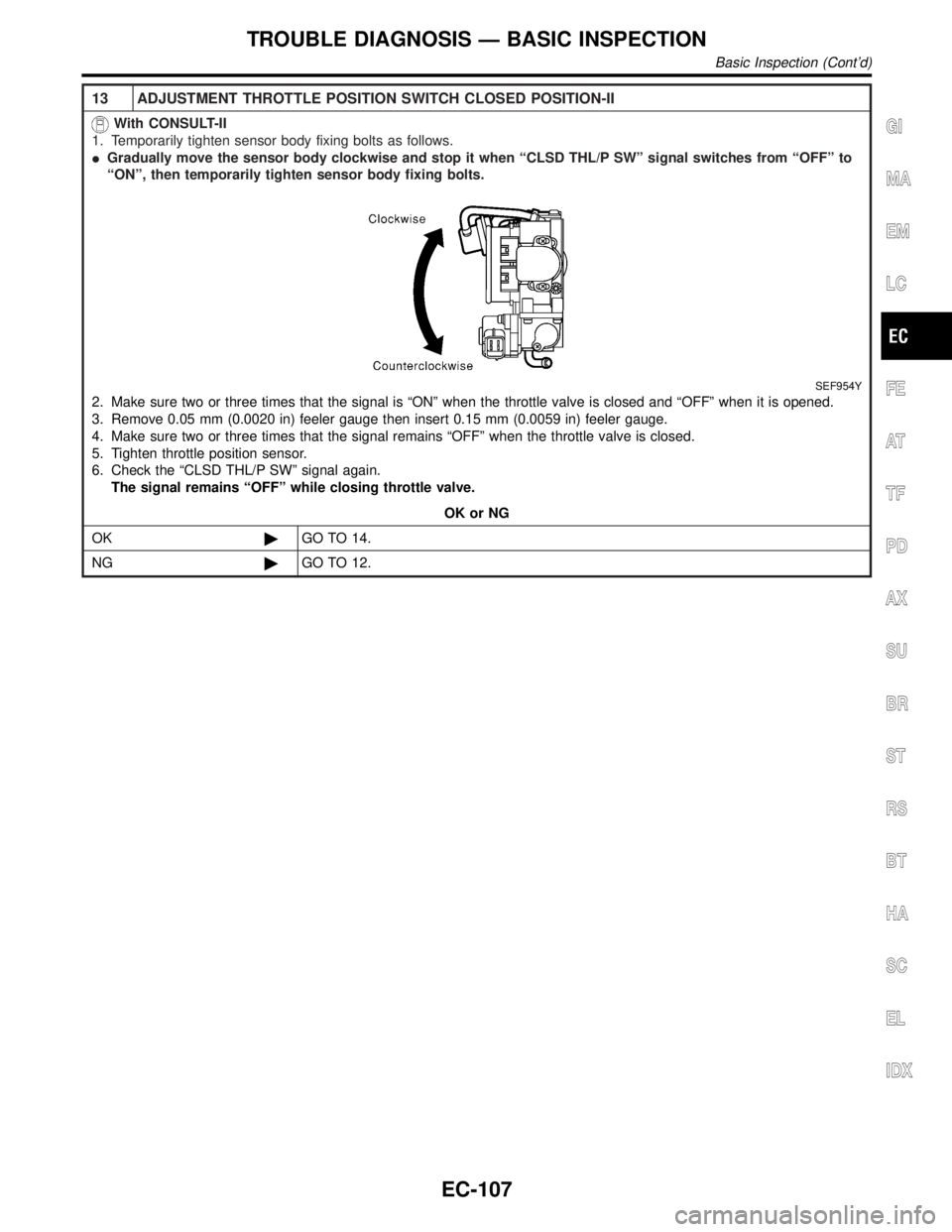
13 ADJUSTMENT THROTTLE POSITION SWITCH CLOSED POSITION-II
With CONSULT-II
1. Temporarily tighten sensor body fixing bolts as follows.
IGradually move the sensor body clockwise and stop it when ªCLSD THL/P SWº signal switches from ªOFFº to
ªONº, then temporarily tighten sensor body fixing bolts.
SEF954Y
2. Make sure two or three times that the signal is ªONº when the throttle valve is closed and ªOFFº when it is opened.
3. Remove 0.05 mm (0.0020 in) feeler gauge then insert 0.15 mm (0.0059 in) feeler gauge.
4. Make sure two or three times that the signal remains ªOFFº when the throttle valve is closed.
5. Tighten throttle position sensor.
6. Check the ªCLSD THL/P SWº signal again.
The signal remains ªOFFº while closing throttle valve.
OK or NG
OK©GO TO 14.
NG©GO TO 12.
GI
MA
EM
LC
FE
AT
TF
PD
AX
SU
BR
ST
RS
BT
HA
SC
EL
IDX
TROUBLE DIAGNOSIS Ð BASIC INSPECTION
Basic Inspection (Cont'd)
EC-107
Page 645 of 2395
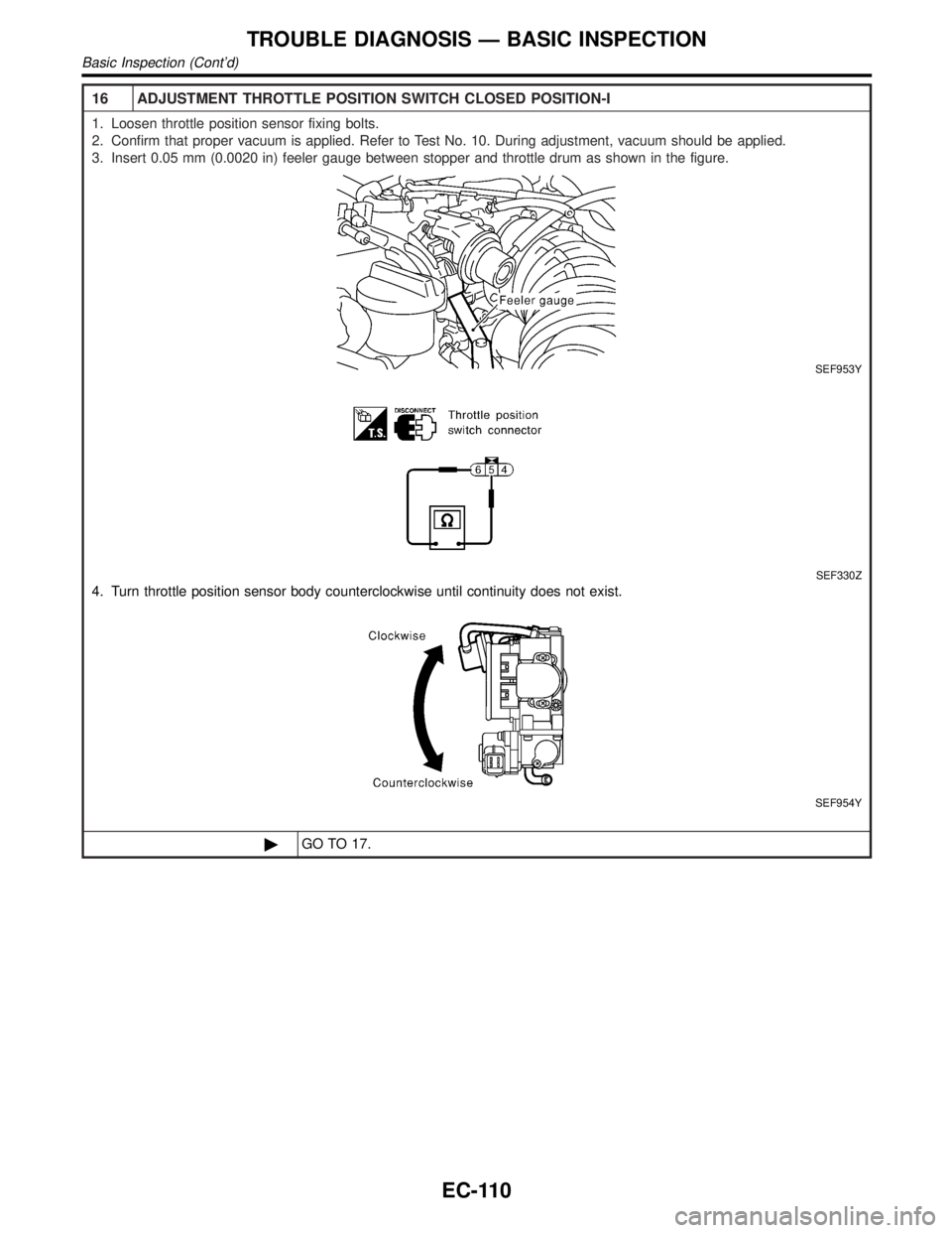
16 ADJUSTMENT THROTTLE POSITION SWITCH CLOSED POSITION-I
1. Loosen throttle position sensor fixing bolts.
2. Confirm that proper vacuum is applied. Refer to Test No. 10. During adjustment, vacuum should be applied.
3. Insert 0.05 mm (0.0020 in) feeler gauge between stopper and throttle drum as shown in the figure.
SEF953Y
SEF330Z
4. Turn throttle position sensor body counterclockwise until continuity does not exist.
SEF954Y
©GO TO 17.
TROUBLE DIAGNOSIS Ð BASIC INSPECTION
Basic Inspection (Cont'd)
EC-110
Page 646 of 2395
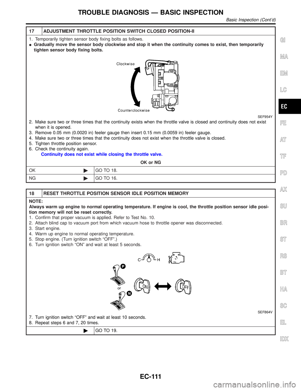
17 ADJUSTMENT THROTTLE POSITION SWITCH CLOSED POSITION-II
1. Temporarily tighten sensor body fixing bolts as follows.
IGradually move the sensor body clockwise and stop it when the continuity comes to exist, then temporarily
tighten sensor body fixing bolts.
SEF954Y
2. Make sure two or three times that the continuity exists when the throttle valve is closed and continuity does not exist
when it is opened.
3. Remove 0.05 mm (0.0020 in) feeler gauge then insert 0.15 mm (0.0059 in) feeler gauge.
4. Make sure two or three times that the continuity does not exist when the throttle valve is closed.
5. Tighten throttle position sensor.
6. Check the continuity again.
Continuity does not exist while closing the throttle valve.
OK or NG
OK©GO TO 18.
NG©GO TO 16.
18 RESET THROTTLE POSITION SENSOR IDLE POSITION MEMORY
NOTE:
Always warm up engine to normal operating temperature. If engine is cool, the throttle position sensor idle posi-
tion memory will not be reset correctly.
1. Confirm that proper vacuum is applied. Refer to Test No. 10.
2. Attach blind cap to vacuum port from which vacuum hose to throttle opener was disconnected.
3. Start engine.
4. Warm up engine to normal operating temperature.
5. Stop engine. (Turn ignition switch ªOFFº.)
6. Turn ignition switch ªONº and wait at least 5 seconds.
SEF864V
7. Turn ignition switch ªOFFº and wait at least 10 seconds.
8. Repeat steps 6 and 7, 20 times.
©GO TO 19.
GI
MA
EM
LC
FE
AT
TF
PD
AX
SU
BR
ST
RS
BT
HA
SC
EL
IDX
TROUBLE DIAGNOSIS Ð BASIC INSPECTION
Basic Inspection (Cont'd)
EC-111