engine coolant INFINITI QX4 2001 Factory Service Manual
[x] Cancel search | Manufacturer: INFINITI, Model Year: 2001, Model line: QX4, Model: INFINITI QX4 2001Pages: 2395, PDF Size: 43.2 MB
Page 13 of 2395
IBefore assembly, apply a coat of recommended ATF to all
parts. Apply petroleum jelly to protect O-rings and seals, or
hold bearings and washers in place during assembly. Do not
use grease.
IExtreme care should be taken to avoid damage to O-rings,
seals and gaskets when assembling.
IReplace ATF cooler if excessive foreign material is found in oil
pan or clogging strainer. Refer to ªATF COOLER SERVICEº,
AT-9.
IAfter overhaul, refill the transmission with new ATF.
IWhen the A/T drain plug is removed, only some of the fluid is
drained. Old A/T fluid will remain in torque converter and ATF
cooling system.
Always follow the procedures when changing A/T fluid. Refer
to MA-21, ªChanging A/T Fluidº.
Service Notice or PrecautionsNBAT0004FAIL-SAFENBAT0004S01The TCM has an electronic Fail-Safe (limp home mode). This allows the vehicle to be driven even if a major
electrical input/output device circuit is damaged.
Under Fail-Safe, the vehicle always runs in third gear, even with a shift lever position of ª1º, ª2º or ªDº. The
customer may complain of sluggish or poor acceleration.
When the ignition key is turned ªONº following Fail-Safe operation, O/D OFF indicator lamp blinks for about
8 seconds. (For ªTCM SELF-DIAGNOSTIC PROCEDURE (No Tools)º, refer to AT-46.)
Fail-Safe may occur without electrical circuit damage if the vehicle is driven under extreme conditions (such
as excessive wheel spin followed by sudden braking). To recover normal shift pattern, turn the ignition key
ªOFFº for 5 seconds, then ªONº.
The blinking of the O/D OFF indicator lamp for about 8 seconds will appear only once and be cleared. The
customer may resume normal driving conditions.
Always follow the ªWORK FLOWº (Refer to AT-57).
The SELF-DIAGNOSIS results will be as follows:
The first SELF-DIAGNOSIS will indicate damage to the vehicle speed sensor or the revolution sensor.
During the next SELF-DIAGNOSIS, performed after checking the sensor, no damages will be indicated.
TORQUE CONVERTER SERVICENBAT0004S04The torque converter should be replaced under any of the following conditions:
IExternal leaks in the hub weld area.
IConverter hub is scored or damaged.
IConverter pilot is broken, damaged or fits poorly into crankshaft.
ISteel particles are found after flushing the cooler and cooler lines.
IPump is damaged or steel particles are found in the converter.
IVehicle has TCC shudder and/or no TCC apply. Replace only after all hydraulic and electrical diagnoses
have been made. (Converter clutch material may be glazed.)
IConverter is contaminated with engine coolant containing antifreeze.
IInternal failure of stator roller clutch.
IHeavy clutch debris due to overheating (blue converter).
ISteel particles or clutch lining material found in fluid filter or on magnet when no internal parts in unit are
worn or damaged Ð indicates that lining material came from converter.
The torque converter should not be replaced if:
IThe fluid has an odor, is discolored, and there is no evidence of metal or clutch facing particles.
PRECAUTIONS
Precautions (Cont'd)
AT-8
Page 39 of 2395

SAT014K
If the DTC is being detected currently, the time data will be ª0º.
SAT015K
If a 1st trip DTC is stored in the ECM, the time data will be ª1tº.
SAT016K
Freeze Frame Data and 1st Trip Freeze Frame DataNBAT0016S0101The ECM has a memory function, which stores the driving condition such as fuel system status, calculated
load value, engine coolant temperature, short term fuel trim, long term fuel trim, engine speed and vehicle
speed at the moment the ECM detects a malfunction.
Data which are stored in the ECM memory, along with the 1st trip DTC, are called 1st trip freeze frame data,
and the data, stored together with the DTC data, are called freeze frame data and displayed on CONSULT-II
or GST. The 1st trip freeze frame data can only be displayed on the CONSULT-II screen, not on the GST. For
detail, refer to EC-81, ªCONSULT-IIº.
Only one set of freeze frame data (either 1st trip freeze frame data of freeze frame data) can be stored in the
ECM. 1st trip freeze frame data is stored in the ECM memory along with the 1st trip DTC. There is no prior-
ity for 1st trip freeze frame data and it is updated each time a different 1st trip DTC is detected. However, once
freeze frame data (2nd trip detection/MIL on) is stored in the ECM memory, 1st trip freeze frame data is no
longer stored. Remember, only one set of freeze frame data can be stored in the ECM. The ECM has the fol-
lowing priorities to update the data.
ON BOARD DIAGNOSTIC SYSTEM DESCRIPTION
OBD-II Diagnostic Trouble Code (DTC) (Cont'd)
AT-34
Page 369 of 2395
SBR686C
Precautions
PRECAUTIONSNBAX0001IWhen installing rubber parts, final tightening must be car-
ried out under unladen condition* with tires on ground.
*Fuel, radiator coolant and engine oil full. Spare tire, jack,
hand tools and mats in designated positions.
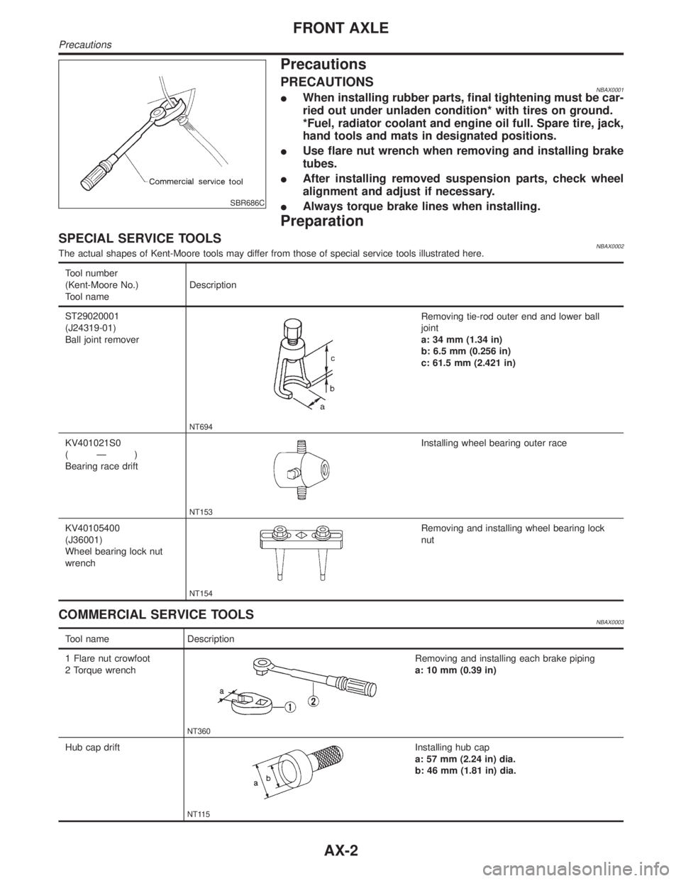
IUse flare nut wrench when removing and installing brake
tubes.
IAfter installing removed suspension parts, check wheel
alignment and adjust if necessary.
IAlways torque brake lines when installing.
Preparation
SPECIAL SERVICE TOOLSNBAX0002The actual shapes of Kent-Moore tools may differ from those of special service tools illustrated here.
Tool number
(Kent-Moore No.)
Tool nameDescription
ST29020001
(J24319-01)
Ball joint remover
NT694
Removing tie-rod outer end and lower ball
joint
a: 34 mm (1.34 in)
b: 6.5 mm (0.256 in)
c: 61.5 mm (2.421 in)
KV401021S0
(Ð)
Bearing race drift
NT153
Installing wheel bearing outer race
KV40105400
(J36001)
Wheel bearing lock nut
wrench
NT154
Removing and installing wheel bearing lock
nut
COMMERCIAL SERVICE TOOLSNBAX0003
Tool name Description
1 Flare nut crowfoot
2 Torque wrench
NT360
Removing and installing each brake piping
a: 10 mm (0.39 in)
Hub cap drift
NT115
Installing hub cap
a: 57 mm (2.24 in) dia.
b: 46 mm (1.81 in) dia.
FRONT AXLE
Precautions
AX-2
Page 384 of 2395
SBR686C
Precautions
PRECAUTIONSNBAX0023IWhen installing rubber parts, final tightening must be car-
ried out under unladen condition* with tires on ground.
*Fuel, radiator coolant and engine oil full. Spare tire, jack,
hand tools and mats in designated positions.
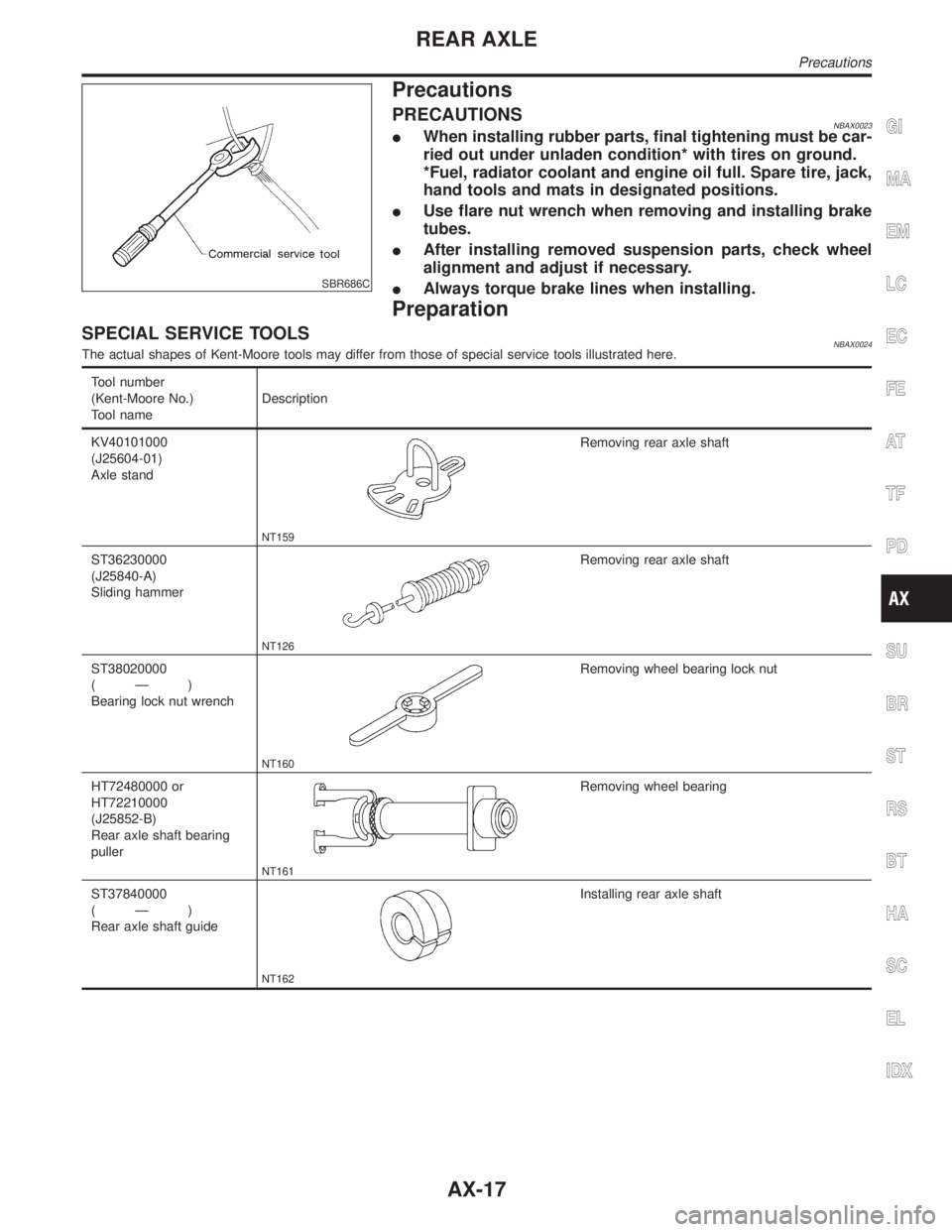
IUse flare nut wrench when removing and installing brake
tubes.
IAfter installing removed suspension parts, check wheel
alignment and adjust if necessary.
IAlways torque brake lines when installing.
Preparation
SPECIAL SERVICE TOOLSNBAX0024The actual shapes of Kent-Moore tools may differ from those of special service tools illustrated here.
Tool number
(Kent-Moore No.)
Tool nameDescription
KV40101000
(J25604-01)
Axle stand
NT159
Removing rear axle shaft
ST36230000
(J25840-A)
Sliding hammer
NT126
Removing rear axle shaft
ST38020000
(Ð)
Bearing lock nut wrench
NT160
Removing wheel bearing lock nut
HT72480000 or
HT72210000
(J25852-B)
Rear axle shaft bearing
puller
NT161
Removing wheel bearing
ST37840000
(Ð)
Rear axle shaft guide
NT162
Installing rear axle shaft
GI
MA
EM
LC
EC
FE
AT
TF
PD
SU
BR
ST
RS
BT
HA
SC
EL
IDX
REAR AXLE
Precautions
AX-17
Page 401 of 2395
InspectionNBBR0014CAUTION:
ICarefully monitor brake fluid level at master cylinder.
IUse new brake fluid ªDOT 3º.
IBe careful not to splash brake fluid on painted areas; it
may cause paint damage. If brake fluid is splashed on
paint areas, wash it away with water immediately.
IDepress pedal slowly when raising front brake pressure.
ICheck rear brake pressure 2 seconds after front brake
pressure reaches specified value.
IDisconnect harness connectors from ABS actuator and
electric unit before checking.
SBR212E
1. Park vehicle on a level surface with vehicle unloaded*.
* Fuel, radiator coolant and engine oil full. Spare tire, jack,
hand tools and mats in designated positions.
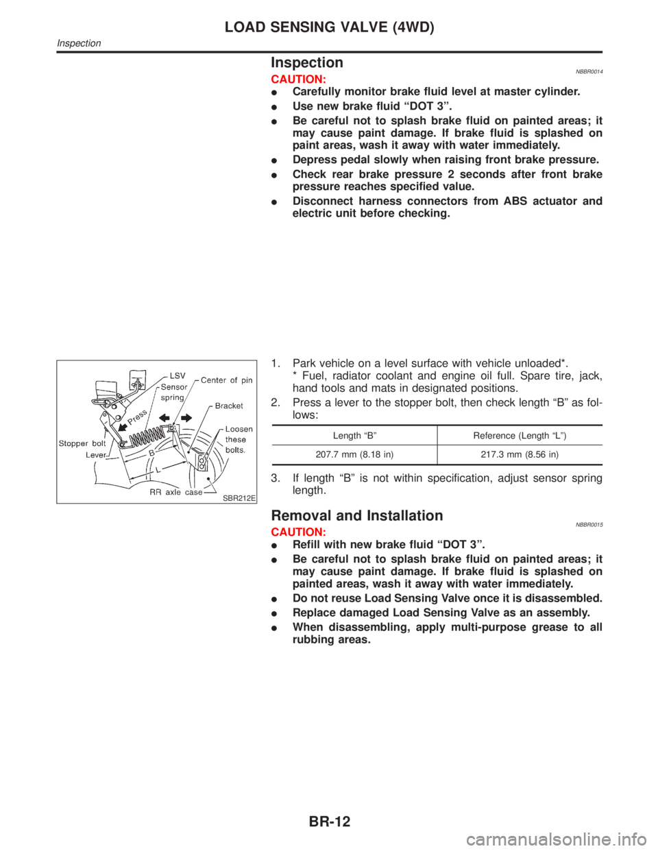
2. Press a lever to the stopper bolt, then check length ªBº as fol-
lows:
Length ªBº Reference (Length ªLº)
207.7 mm (8.18 in) 217.3 mm (8.56 in)
3. If length ªBº is not within specification, adjust sensor spring
length.
Removal and InstallationNBBR0015CAUTION:
IRefill with new brake fluid ªDOT 3º.
IBe careful not to splash brake fluid on painted areas; it
may cause paint damage. If brake fluid is splashed on
painted areas, wash it away with water immediately.
IDo not reuse Load Sensing Valve once it is disassembled.
IReplace damaged Load Sensing Valve as an assembly.
IWhen disassembling, apply multi-purpose grease to all
rubbing areas.
LOAD SENSING VALVE (4WD)
Inspection
BR-12
Page 537 of 2395

CONSULT-II Reference Value in Data Monitor
Mode ........................................................................150
ECM Terminals and Reference Value .....................150
On Board Diagnosis Logic.......................................151
Possible Cause ........................................................151
DTC Confirmation Procedure ..................................151
Overall Function Check ...........................................153
Wiring Diagram ........................................................154
Diagnostic Procedure ..............................................155
DTC P0105 ABSOLUTE PRESSURE SENSOR........158
Component Description ...........................................158
ECM Terminals and Reference Value .....................158
On Board Diagnosis Logic.......................................158
Possible Cause ........................................................159
DTC Confirmation Procedure ..................................159
Wiring Diagram ........................................................160
Diagnostic Procedure ..............................................161
DTC P0110 INTAKE AIR TEMPERATURE
SENSOR......................................................................164
Component Description ...........................................164
On Board Diagnosis Logic.......................................164
Possible Cause ........................................................164
DTC Confirmation Procedure ..................................164
Wiring Diagram ........................................................166
Diagnostic Procedure ..............................................167
DTC P0115 ENGINE COOLANT TEMPERATURE
SENSOR (ECTS) (CIRCUIT).......................................169
Component Description ...........................................169
On Board Diagnosis Logic.......................................169
Possible Cause ........................................................170
DTC Confirmation Procedure ..................................170
Wiring Diagram ........................................................171
Diagnostic Procedure ..............................................172
DTC P0120 THROTTLE POSITION SENSOR...........174
Description ...............................................................174
CONSULT-II Reference Value in Data Monitor
Mode ........................................................................174
ECM Terminals and Reference Value .....................175
On Board Diagnosis Logic.......................................175
Possible Cause ........................................................175
DTC Confirmation Procedure ..................................176
Wiring Diagram ........................................................180
Diagnostic Procedure ..............................................181
DTC P0125 ENGINE COOLANT TEMPERATURE
SENSOR (ECTS).........................................................187
Description ...............................................................187
On Board Diagnosis Logic.......................................187
Possible Cause ........................................................188
DTC Confirmation Procedure ..................................188
Wiring Diagram ........................................................189
Diagnostic Procedure ..............................................190DTC P0130, P0150 HEATED OXYGEN SENSOR 1
(FRONT) (BANK 1)/(BANK 2) (CIRCUIT)..................192
Component Description ...........................................192
CONSULT-II Reference Value in Data Monitor
Mode ........................................................................192
ECM Terminals and Reference Value .....................192
On Board Diagnosis Logic.......................................193
Possible Cause ........................................................193
DTC Confirmation Procedure ..................................194
Overall Function Check ...........................................194
Wiring Diagram ........................................................196
Diagnostic Procedure ..............................................198
DTC P0131, P0151 HEATED OXYGEN SENSOR 1
(FRONT) (BANK 1)/(BANK 2) (LEAN SHIFT
MONITORING).............................................................202
Component Description ...........................................202
CONSULT-II Reference Value in Data Monitor
Mode ........................................................................202
ECM Terminals and Reference Value .....................202
On Board Diagnosis Logic.......................................203
Possible Cause ........................................................203
DTC Confirmation Procedure ..................................203
Overall Function Check ...........................................204
Diagnostic Procedure ..............................................205
DTC P0132, P0152 HEATED OXYGEN SENSOR 1
(FRONT) (BANK 1)/(BANK 2) (RICH SHIFT
MONITORING).............................................................210
Component Description ...........................................210
CONSULT-II Reference Value in Data Monitor
Mode ........................................................................210
ECM Terminals and Reference Value .....................210
On Board Diagnosis Logic....................................... 211
Possible Cause ........................................................ 211
DTC Confirmation Procedure .................................. 211
Overall Function Check ...........................................212
Diagnostic Procedure ..............................................213
DTC P0133, P0153 HEATED OXYGEN SENSOR 1
(FRONT) (BANK 1)/(BANK 2) (RESPONSE
MONITORING).............................................................218
Component Description ...........................................218
CONSULT-II Reference Value in Data Monitor
Mode ........................................................................218
ECM Terminals and Reference Value .....................218
On Board Diagnosis Logic.......................................219
Possible Cause ........................................................219
DTC Confirmation Procedure ..................................220
Overall Function Check ...........................................221
Wiring Diagram ........................................................222
Diagnostic Procedure ..............................................224
DTC P0134, P0154 HEATED OXYGEN SENSOR 1
(FRONT) (BANK 1)/(BANK 2) (HIGH VOLTAGE)......231
Component Description ...........................................231
CONTENTS(Cont'd)
EC-2
Page 542 of 2395

CONSULT-II Reference Value in Data Monitor
Mode ........................................................................585
ECM Terminals and Reference Value .....................585
On Board Diagnosis Logic.......................................586
Possible Cause ........................................................586
DTC Confirmation Procedure ..................................586
Wiring Diagram ........................................................587
Diagnostic Procedure ..............................................588
DTC P1491 VACUUM CUT VALVE BYPASS
VALVE..........................................................................591
Description ...............................................................591
CONSULT-II Reference Value in Data Monitor
Mode ........................................................................591
ECM Terminals and Reference Value .....................591
On Board Diagnosis Logic.......................................592
Possible Cause ........................................................592
DTC Confirmation Procedure ..................................592
Overall Function Check ...........................................593
Wiring Diagram ........................................................594
Diagnostic Procedure ..............................................595
DTC P1605 A/T DIAGNOSIS COMMUNICATION
LINE.............................................................................603
Component Description ...........................................603
On Board Diagnosis Logic.......................................603
Possible Cause ........................................................603
DTC Confirmation Procedure ..................................603
DTC P1706 PARK/NEUTRAL POSITION (PNP)
SWITCH.......................................................................604
Component Description ...........................................604
CONSULT-II Reference Value in Data Monitor
Mode ........................................................................604
ECM Terminals and Reference Value .....................604
On Board Diagnosis Logic.......................................604
Possible Cause ........................................................604
DTC Confirmation Procedure ..................................605
Overall Function Check ...........................................606
Wiring Diagram ........................................................607
Diagnostic Procedure ..............................................608
VARIABLE INDUCTION AIR CONTROL SYSTEM
(VIAS)...........................................................................610
Description ...............................................................610
ECM Terminals and Reference Value ..................... 611
Wiring Diagram ........................................................612
Diagnostic Procedure ..............................................613
INJECTOR...................................................................616
Component Description ...........................................616
CONSULT-II Reference Value in Data Monitor
Mode ........................................................................616
ECM Terminals and Reference Value .....................616
Wiring Diagram ........................................................617Diagnostic Procedure ..............................................618
START SIGNAL...........................................................621
CONSULT-II Reference Value in Data Monitor
Mode ........................................................................621
ECM Terminals and Reference Value .....................621
Wiring Diagram ........................................................622
Diagnostic Procedure ..............................................623
FUEL PUMP.................................................................625
System Description ..................................................625
Component Description ...........................................625
CONSULT-II Reference Value in Data Monitor
Mode ........................................................................625
ECM Terminals and Reference Value .....................626
Wiring Diagram ........................................................627
Diagnostic Procedure ..............................................628
POWER STEERING OIL PRESSURE SWITCH.........634
Component Description ...........................................634
CONSULT-II Reference Value in Data Monitor
Mode ........................................................................634
ECM Terminals and Reference Value .....................634
Wiring Diagram ........................................................635
Diagnostic Procedure ..............................................636
REFRIGERANT PRESSURE SENSOR......................639
Description ...............................................................639
ECM Terminals and Reference Value .....................639
Wiring Diagram ........................................................640
Diagnostic Procedure ..............................................641
ELECTRICAL LOAD SIGNAL.....................................643
ECM Terminals and Reference Value .....................643
Wiring Diagram ........................................................644
Diagnostic Procedure ..............................................645
MIL & DATA LINK CONNECTORS............................648
Wiring Diagram ........................................................648
SERVICE DATA AND SPECIFICATIONS (SDS).......649
Fuel Pressure Regulator..........................................649
Idle Speed and Ignition Timing ................................649
Mass Air Flow Sensor..............................................649
Engine Coolant Temperature Sensor ......................649
Heated Oxygen Sensor 1 Heater (Front) ................649
Fuel Pump ...............................................................649
IACV-AAC Valve ......................................................649
Injector .....................................................................649
Resistor ....................................................................649
Throttle Position Sensor ..........................................650
Calculated Load Value.............................................650
Intake Air Temperature Sensor ................................650
Heated Oxygen Sensor 2 Heater (Rear).................650
Crankshaft Position Sensor (REF) ..........................650
Fuel Tank Temperature Sensor ...............................650
Camshaft Position Sensor (PHASE) .......................650GI
MA
EM
LC
FE
AT
TF
PD
AX
SU
BR
ST
RS
BT
HA
SC
EL
IDX
CONTENTS(Cont'd)
EC-7
Page 543 of 2395

Alphabetical & P No. Index for DTCNBEC0001ALPHABETICAL INDEX FOR DTCNBEC0001S01
Items
(CONSULT-II screen terms)DTC*1 Reference page
Unable to access ECM Ð EC-117
ABSL PRES SEN/CIRC P0105 EC-158
AIR TEMP SEN/CIRC P0110 EC-164
A/T 1ST GR FNCTN P0731 AT-136
A/T 2ND GR FNCTN P0732 AT-143
A/T 3RD GR FNCTN P0733 AT-151
A/T 4TH GR FNCTN P0734 AT-157
A/T COMM LINE P0600*2 EC-440
A/T DIAG COMM LINE P1605 EC-603
A/T TCC S/V FNCTN P0744 AT-170
ATF TEMP SEN/CIRC P0710 AT-116
CAM PS/CIRC (PHS) P0340 EC-342
CLOSED LOOP-B1 P1148 EC-491
CLOSED LOOP-B2 P1168 EC-491
CLOSED TP SW/CIRC P0510 EC-431
COOLANT T SEN/CIRC*3 P0115 EC-169
*COOLANT T SEN/CIRC P0125 EC-187
CPS/CIRC (POS) COG P1336 EC-517
CPS/CIRCUIT (POS) P0335 EC-334
CPS/CIRCUIT (REF) P1335 EC-510
CYL 1 MISFIRE P0301 EC-320
CYL 2 MISFIRE P0302 EC-320
CYL 3 MISFIRE P0303 EC-320
CYL 4 MISFIRE P0304 EC-320
CYL 5 MISFIRE P0305 EC-320
CYL 6 MISFIRE P0306 EC-320
ECMP0605 EC-444
ENGINE SPEED SIG P0725 AT-130
ENG OVER TEMP P0217 EC-314
ENG OVER TEMP P1217 LC-24
EVAP GROSS LEAK P0455 EC-394
EVAP PURG FLOW/MON P1447 EC-561
EVAP SYS PRES SEN P0450 EC-381
EVAP SMALL LEAK P0440 EC-352
EVAP VERY SMALL LEAK P1441 EC-526
TROUBLE DIAGNOSIS Ð INDEX
Alphabetical & P No. Index for DTC
EC-8
Page 554 of 2395

Tool name
(Kent-Moore No.)Description
Socket wrench
NT705
Removing and installing engine coolant tempera-
ture sensor
Oxygen sensor thread
cleaner
(J-43897-18)
(J-43897-12)
NT828
Reconditioning the exhaust system threads before
installing a new oxygen sensor. Use with anti-seize
lubricant shown below.
a: J-43897-18 18 mm diameter with pitch 1.5
mm, for Zirconia Oxygen Sensor
b: J-43897-12 12 mm diameter with pitch 1.25
mm, for Titania Oxygen Sensor
Anti-seize lubricant
(Permatex
TM133AR or
equivalent meeting MIL
specification MIL-A-907)
NT779
Lubricating oxygen sensor thread cleaning tool
when reconditioning exhaust system threads.
GI
MA
EM
LC
FE
AT
TF
PD
AX
SU
BR
ST
RS
BT
HA
SC
EL
IDX
PREPARATION
Commercial Service Tools (Cont'd)
EC-19
Page 562 of 2395
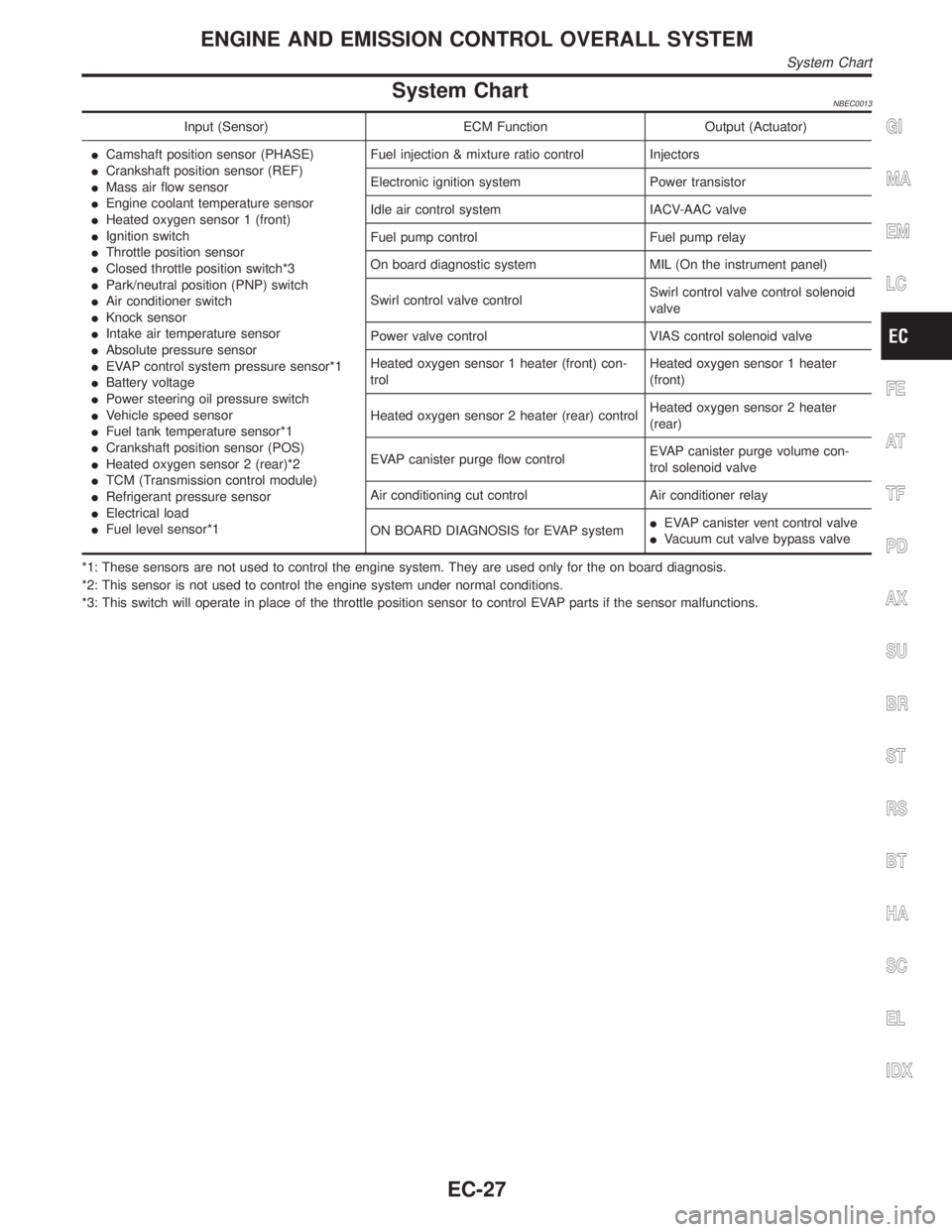
System ChartNBEC0013
Input (Sensor) ECM Function Output (Actuator)
ICamshaft position sensor (PHASE)
ICrankshaft position sensor (REF)
IMass air flow sensor
IEngine coolant temperature sensor
IHeated oxygen sensor 1 (front)
IIgnition switch
IThrottle position sensor
IClosed throttle position switch*3
IPark/neutral position (PNP) switch
IAir conditioner switch
IKnock sensor
IIntake air temperature sensor
IAbsolute pressure sensor
IEVAP control system pressure sensor*1
IBattery voltage
IPower steering oil pressure switch
IVehicle speed sensor
IFuel tank temperature sensor*1
ICrankshaft position sensor (POS)
IHeated oxygen sensor 2 (rear)*2
ITCM (Transmission control module)
IRefrigerant pressure sensor
IElectrical load
IFuel level sensor*1Fuel injection & mixture ratio control Injectors
Electronic ignition system Power transistor
Idle air control system IACV-AAC valve
Fuel pump control Fuel pump relay
On board diagnostic system MIL (On the instrument panel)
Swirl control valve controlSwirl control valve control solenoid
valve
Power valve control VIAS control solenoid valve
Heated oxygen sensor 1 heater (front) con-
trolHeated oxygen sensor 1 heater
(front)
Heated oxygen sensor 2 heater (rear) controlHeated oxygen sensor 2 heater
(rear)
EVAP canister purge flow controlEVAP canister purge volume con-
trol solenoid valve
Air conditioning cut control Air conditioner relay
ON BOARD DIAGNOSIS for EVAP systemIEVAP canister vent control valve
IVacuum cut valve bypass valve
*1: These sensors are not used to control the engine system. They are used only for the on board diagnosis.
*2: This sensor is not used to control the engine system under normal conditions.
*3: This switch will operate in place of the throttle position sensor to control EVAP parts if the sensor malfunctions.GI
MA
EM
LC
FE
AT
TF
PD
AX
SU
BR
ST
RS
BT
HA
SC
EL
IDX
ENGINE AND EMISSION CONTROL OVERALL SYSTEM
System Chart
EC-27