flat tire INFINITI QX4 2001 Factory Service Manual
[x] Cancel search | Manufacturer: INFINITI, Model Year: 2001, Model line: QX4, Model: INFINITI QX4 2001Pages: 2395, PDF Size: 43.2 MB
Page 447 of 2395
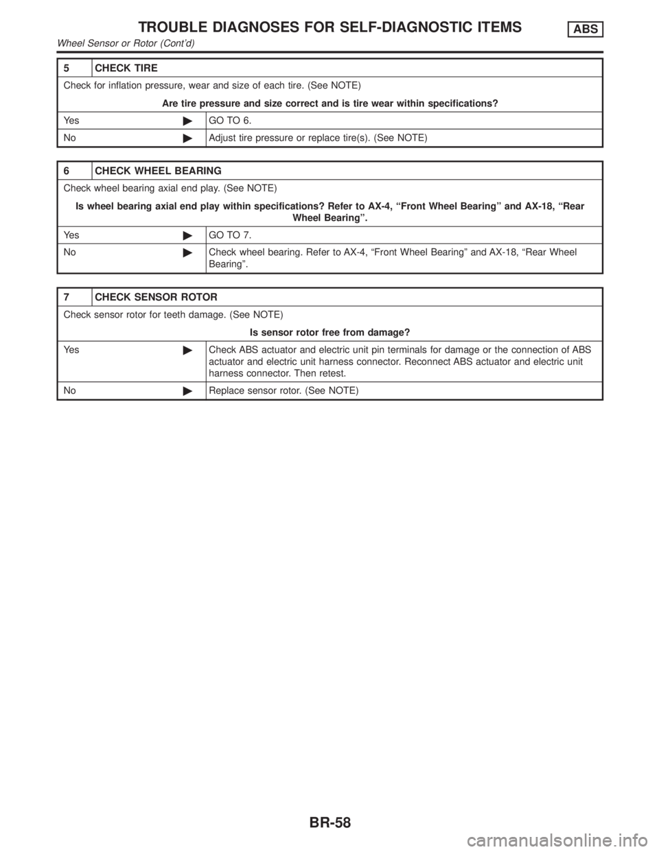
5 CHECK TIRE
Check for inflation pressure, wear and size of each tire. (See NOTE)
Are tire pressure and size correct and is tire wear within specifications?
Ye s©GO TO 6.
No©Adjust tire pressure or replace tire(s). (See NOTE)
6 CHECK WHEEL BEARING
Check wheel bearing axial end play. (See NOTE)
Is wheel bearing axial end play within specifications? Refer to AX-4, ªFront Wheel Bearingº and AX-18, ªRear
Wheel Bearingº.
Ye s©GO TO 7.
No©Check wheel bearing. Refer to AX-4, ªFront Wheel Bearingº and AX-18, ªRear Wheel
Bearingº.
7 CHECK SENSOR ROTOR
Check sensor rotor for teeth damage. (See NOTE)
Is sensor rotor free from damage?
Ye s©Check ABS actuator and electric unit pin terminals for damage or the connection of ABS
actuator and electric unit harness connector. Reconnect ABS actuator and electric unit
harness connector. Then retest.
No©Replace sensor rotor. (See NOTE)
TROUBLE DIAGNOSES FOR SELF-DIAGNOSTIC ITEMSABS
Wheel Sensor or Rotor (Cont'd)
BR-58
Page 1259 of 2395

SEL350X
Aiming AdjustmentNBEL0029Before performing aiming adjustment, make sure of the following.
1) Keep all tires inflated to correct pressure.
2) Place vehicle on level ground.
3) See that vehicle is unloaded (except for full levels of coolant,
engine oil and fuel, and spare tire, jack, and tools). Have the
driver or equivalent weight placed in driver's seat.
Adjust aiming in the vertical direction by turning the adjusting
screw.
MEL327G
1. Set the distance between the screen and the center of the fog
lamp lens as shown at left.
2. Turn front fog lamps ON.
MEL328GA
3. Adjust front fog lamps so that the top edge of the high inten-
sity zone is 200 mm (7.9 in) below the height of the fog lamp
centers as shown at left.
IWhen performing adjustment, if necessary, cover the head-
lamps and opposite fog lamp.
FRONT FOG LAMP
Aiming Adjustment
EL-74
Page 2019 of 2395
SMA632C
SMA631C
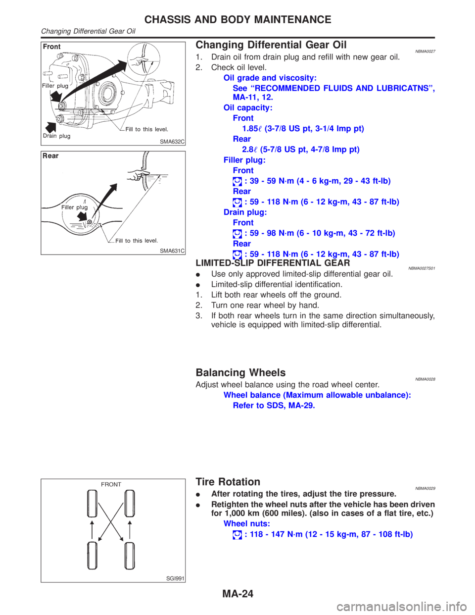
Changing Differential Gear OilNBMA00271. Drain oil from drain plug and refill with new gear oil.
2. Check oil level.
Oil grade and viscosity:
See ªRECOMMENDED FLUIDS AND LUBRICATNSº,
MA-11, 12.
Oil capacity:
Front
1.85(3-7/8 US pt, 3-1/4 Imp pt)
Rear
2.8(5-7/8 US pt, 4-7/8 Imp pt)
Filler plug:
Front
: 39 - 59 N´m (4 - 6 kg-m, 29 - 43 ft-lb)
Rear
: 59 - 118 N´m (6 - 12 kg-m, 43 - 87 ft-lb)
Drain plug:
Front
: 59 - 98 N´m (6 - 10 kg-m, 43 - 72 ft-lb)
Rear
: 59 - 118 N´m (6 - 12 kg-m, 43 - 87 ft-lb)
LIMITED-SLIP DIFFERENTIAL GEARNBMA0027S01IUse only approved limited-slip differential gear oil.
ILimited-slip differential identification.
1. Lift both rear wheels off the ground.
2. Turn one rear wheel by hand.
3. If both rear wheels turn in the same direction simultaneously,
vehicle is equipped with limited-slip differential.
Balancing WheelsNBMA0028Adjust wheel balance using the road wheel center.
Wheel balance (Maximum allowable unbalance):
Refer to SDS, MA-29.
SGI991
Tire RotationNBMA0029IAfter rotating the tires, adjust the tire pressure.
IRetighten the wheel nuts after the vehicle has been driven
for 1,000 km (600 miles). (also in cases of a flat tire, etc.)
Wheel nuts:
: 118 - 147 N´m (12 - 15 kg-m, 87 - 108 ft-lb)
CHASSIS AND BODY MAINTENANCE
Changing Differential Gear Oil
MA-24
Page 2099 of 2395
Precautions
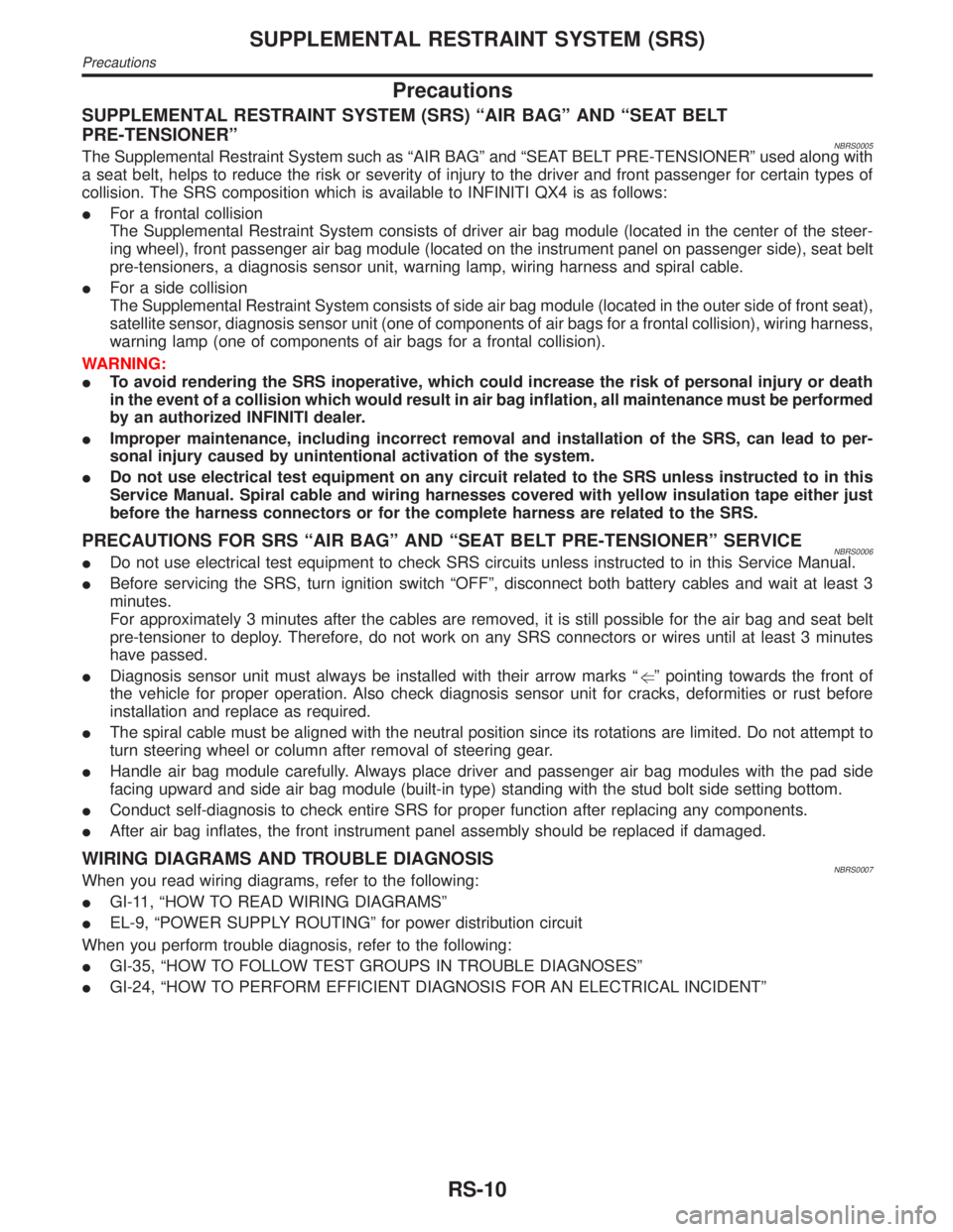
SUPPLEMENTAL RESTRAINT SYSTEM (SRS) ªAIR BAGº AND ªSEAT BELT
PRE-TENSIONERº
NBRS0005The Supplemental Restraint System such as ªAIR BAGº and ªSEAT BELT PRE-TENSIONERº used along with
a seat belt, helps to reduce the risk or severity of injury to the driver and front passenger for certain types of
collision. The SRS composition which is available to INFINITI QX4 is as follows:
IFor a frontal collision
The Supplemental Restraint System consists of driver air bag module (located in the center of the steer-
ing wheel), front passenger air bag module (located on the instrument panel on passenger side), seat belt
pre-tensioners, a diagnosis sensor unit, warning lamp, wiring harness and spiral cable.
IFor a side collision
The Supplemental Restraint System consists of side air bag module (located in the outer side of front seat),
satellite sensor, diagnosis sensor unit (one of components of air bags for a frontal collision), wiring harness,
warning lamp (one of components of air bags for a frontal collision).
WARNING:
ITo avoid rendering the SRS inoperative, which could increase the risk of personal injury or death
in the event of a collision which would result in air bag inflation, all maintenance must be performed
by an authorized INFINITI dealer.
IImproper maintenance, including incorrect removal and installation of the SRS, can lead to per-
sonal injury caused by unintentional activation of the system.
IDo not use electrical test equipment on any circuit related to the SRS unless instructed to in this
Service Manual. Spiral cable and wiring harnesses covered with yellow insulation tape either just
before the harness connectors or for the complete harness are related to the SRS.
PRECAUTIONS FOR SRS ªAIR BAGº AND ªSEAT BELT PRE-TENSIONERº SERVICENBRS0006IDo not use electrical test equipment to check SRS circuits unless instructed to in this Service Manual.
IBefore servicing the SRS, turn ignition switch ªOFFº, disconnect both battery cables and wait at least 3
minutes.
For approximately 3 minutes after the cables are removed, it is still possible for the air bag and seat belt
pre-tensioner to deploy. Therefore, do not work on any SRS connectors or wires until at least 3 minutes
have passed.
IDiagnosis sensor unit must always be installed with their arrow marks ªgº pointing towards the front of
the vehicle for proper operation. Also check diagnosis sensor unit for cracks, deformities or rust before
installation and replace as required.
IThe spiral cable must be aligned with the neutral position since its rotations are limited. Do not attempt to
turn steering wheel or column after removal of steering gear.
IHandle air bag module carefully. Always place driver and passenger air bag modules with the pad side
facing upward and side air bag module (built-in type) standing with the stud bolt side setting bottom.
IConduct self-diagnosis to check entire SRS for proper function after replacing any components.
IAfter air bag inflates, the front instrument panel assembly should be replaced if damaged.
WIRING DIAGRAMS AND TROUBLE DIAGNOSISNBRS0007When you read wiring diagrams, refer to the following:
IGI-11, ªHOW TO READ WIRING DIAGRAMSº
IEL-9, ªPOWER SUPPLY ROUTINGº for power distribution circuit
When you perform trouble diagnosis, refer to the following:
IGI-35, ªHOW TO FOLLOW TEST GROUPS IN TROUBLE DIAGNOSESº
IGI-24, ªHOW TO PERFORM EFFICIENT DIAGNOSIS FOR AN ELECTRICAL INCIDENTº
SUPPLEMENTAL RESTRAINT SYSTEM (SRS)
Precautions
RS-10
Page 2111 of 2395
SBF814E
IReplace air bag module if it has been dropped or sus-
tained an impact.
IDo not expose the air bag module to temperatures exceed-
ing 90ÉC (194ÉF).
IDo not allow oil, grease or water to come in contact with
the air bag module.
IAfter air bag inflates, all parts of front seatback (including
front seatback frame) should be replaced.
SRS684
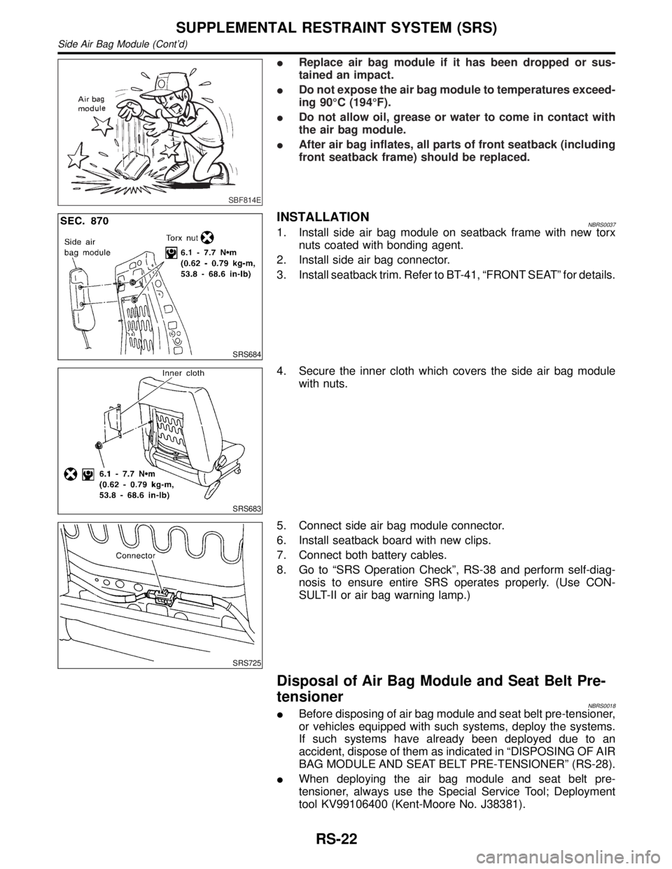
INSTALLATIONNBRS00371. Install side air bag module on seatback frame with new torx
nuts coated with bonding agent.
2. Install side air bag connector.
3. Install seatback trim. Refer to BT-41, ªFRONT SEATº for details.
SRS683
4. Secure the inner cloth which covers the side air bag module
with nuts.
SRS725
5. Connect side air bag module connector.
6. Install seatback board with new clips.
7. Connect both battery cables.
8. Go to ªSRS Operation Checkº, RS-38 and perform self-diag-
nosis to ensure entire SRS operates properly. (Use CON-
SULT-II or air bag warning lamp.)
Disposal of Air Bag Module and Seat Belt Pre-
tensioner
NBRS0018IBefore disposing of air bag module and seat belt pre-tensioner,
or vehicles equipped with such systems, deploy the systems.
If such systems have already been deployed due to an
accident, dispose of them as indicated in ªDISPOSING OF AIR
BAG MODULE AND SEAT BELT PRE-TENSIONERº (RS-28).
IWhen deploying the air bag module and seat belt pre-
tensioner, always use the Special Service Tool; Deployment
tool KV99106400 (Kent-Moore No. J38381).
SUPPLEMENTAL RESTRAINT SYSTEM (SRS)
Side Air Bag Module (Cont'd)
RS-22
Page 2190 of 2395
CAUTION:
Do not hold the steering wheel in a locked position for more
than 15 seconds.
4. If fluid leakage at connectors is noticed, loosen flare nut and
then retighten.
Do not overtighten connector as this can damage O-ring,
washer and connector.
5. Check rack boots for accumulation of power steering fluid.
Bleeding Hydraulic SystemNBST00131. Raise front end of vehicle until wheels are clear of the ground.
2. Add fluid into oil tank to specified level. Then, quickly turn
steering wheel fully to right and left and lightly touch steering
stoppers.
Repeat steering wheel operation until fluid level no longer
decreases.
3. Start engine.
Repeat step 2 above.
IIncomplete air bleeding will cause the following to occur. When
this happens, bleed air again.
a) Air bubbles in reservoir tank
b) Clicking noise in oil pump
c) Excessive buzzing in oil pump
Fluid noise may occur in the valve or oil pump. This is common
when the vehicle is stationary or while turning steering wheel
slowly. This does not affect performance or durability of the system.
SST491B
SST090B
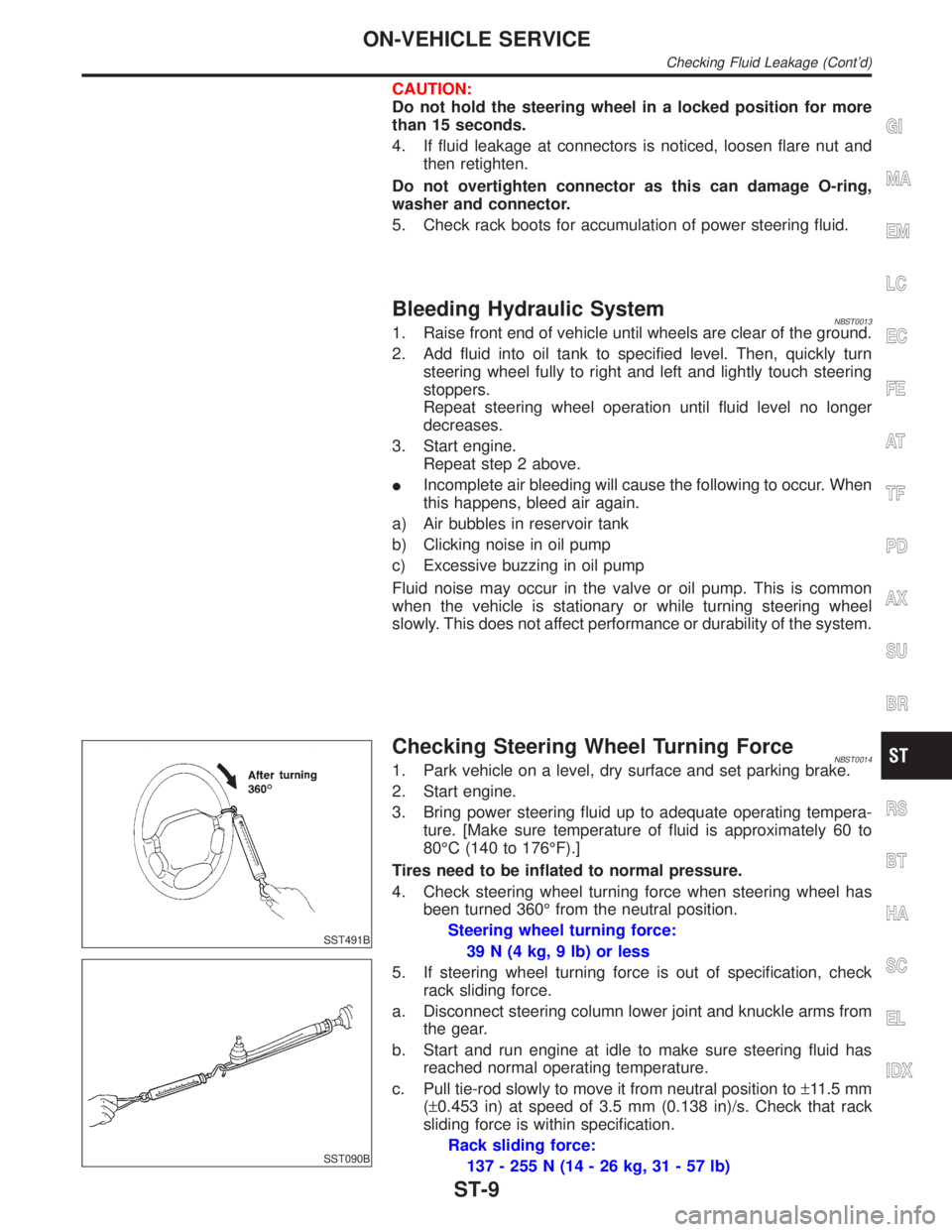
Checking Steering Wheel Turning ForceNBST00141. Park vehicle on a level, dry surface and set parking brake.
2. Start engine.
3. Bring power steering fluid up to adequate operating tempera-
ture. [Make sure temperature of fluid is approximately 60 to
80ÉC (140 to 176ÉF).]
Tires need to be inflated to normal pressure.
4. Check steering wheel turning force when steering wheel has
been turned 360É from the neutral position.
Steering wheel turning force:
39 N (4 kg, 9 lb) or less
5. If steering wheel turning force is out of specification, check
rack sliding force.
a. Disconnect steering column lower joint and knuckle arms from
the gear.
b. Start and run engine at idle to make sure steering fluid has
reached normal operating temperature.
c. Pull tie-rod slowly to move it from neutral position to±11.5 mm
(±0.453 in) at speed of 3.5 mm (0.138 in)/s. Check that rack
sliding force is within specification.
Rack sliding force:
137 - 255 N (14 - 26 kg, 31 - 57 lb)
GI
MA
EM
LC
EC
FE
AT
TF
PD
AX
SU
BR
RS
BT
HA
SC
EL
IDX
ON-VEHICLE SERVICE
Checking Fluid Leakage (Cont'd)
ST-9
Page 2220 of 2395
SMA525A
On-vehicle Service
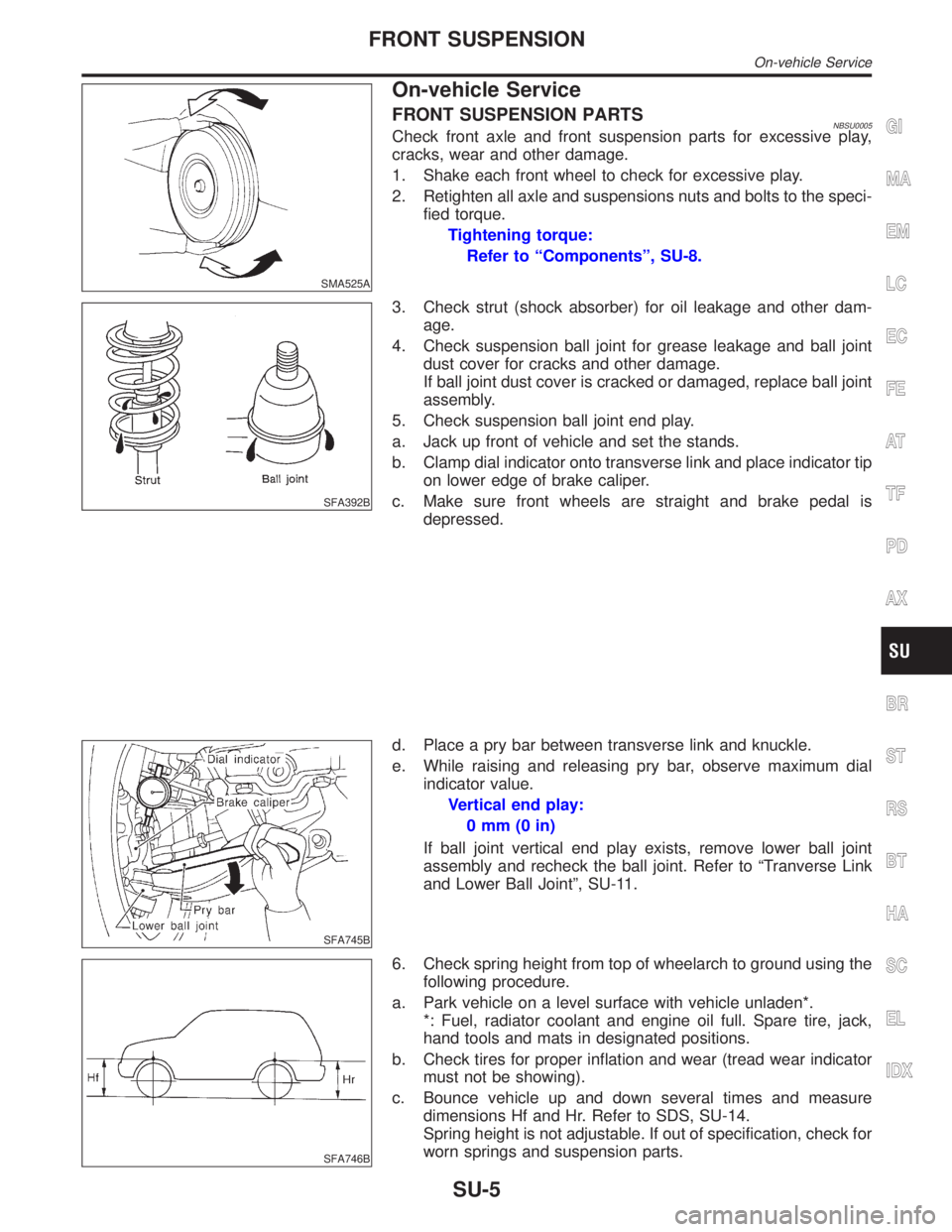
FRONT SUSPENSION PARTSNBSU0005Check front axle and front suspension parts for excessive play,
cracks, wear and other damage.
1. Shake each front wheel to check for excessive play.
2. Retighten all axle and suspensions nuts and bolts to the speci-
fied torque.
Tightening torque:
Refer to ªComponentsº, SU-8.
SFA392B
3. Check strut (shock absorber) for oil leakage and other dam-
age.
4. Check suspension ball joint for grease leakage and ball joint
dust cover for cracks and other damage.
If ball joint dust cover is cracked or damaged, replace ball joint
assembly.
5. Check suspension ball joint end play.
a. Jack up front of vehicle and set the stands.
b. Clamp dial indicator onto transverse link and place indicator tip
on lower edge of brake caliper.
c. Make sure front wheels are straight and brake pedal is
depressed.
SFA745B
d. Place a pry bar between transverse link and knuckle.
e. While raising and releasing pry bar, observe maximum dial
indicator value.
Vertical end play:
0mm(0in)
If ball joint vertical end play exists, remove lower ball joint
assembly and recheck the ball joint. Refer to ªTranverse Link
and Lower Ball Jointº, SU-11.
SFA746B
6. Check spring height from top of wheelarch to ground using the
following procedure.
a. Park vehicle on a level surface with vehicle unladen*.
*: Fuel, radiator coolant and engine oil full. Spare tire, jack,
hand tools and mats in designated positions.
b. Check tires for proper inflation and wear (tread wear indicator
must not be showing).
c. Bounce vehicle up and down several times and measure
dimensions Hf and Hr. Refer to SDS, SU-14.
Spring height is not adjustable. If out of specification, check for
worn springs and suspension parts.
GI
MA
EM
LC
EC
FE
AT
TF
PD
AX
BR
ST
RS
BT
HA
SC
EL
IDX
FRONT SUSPENSION
On-vehicle Service
SU-5
Page 2221 of 2395
SFA975B
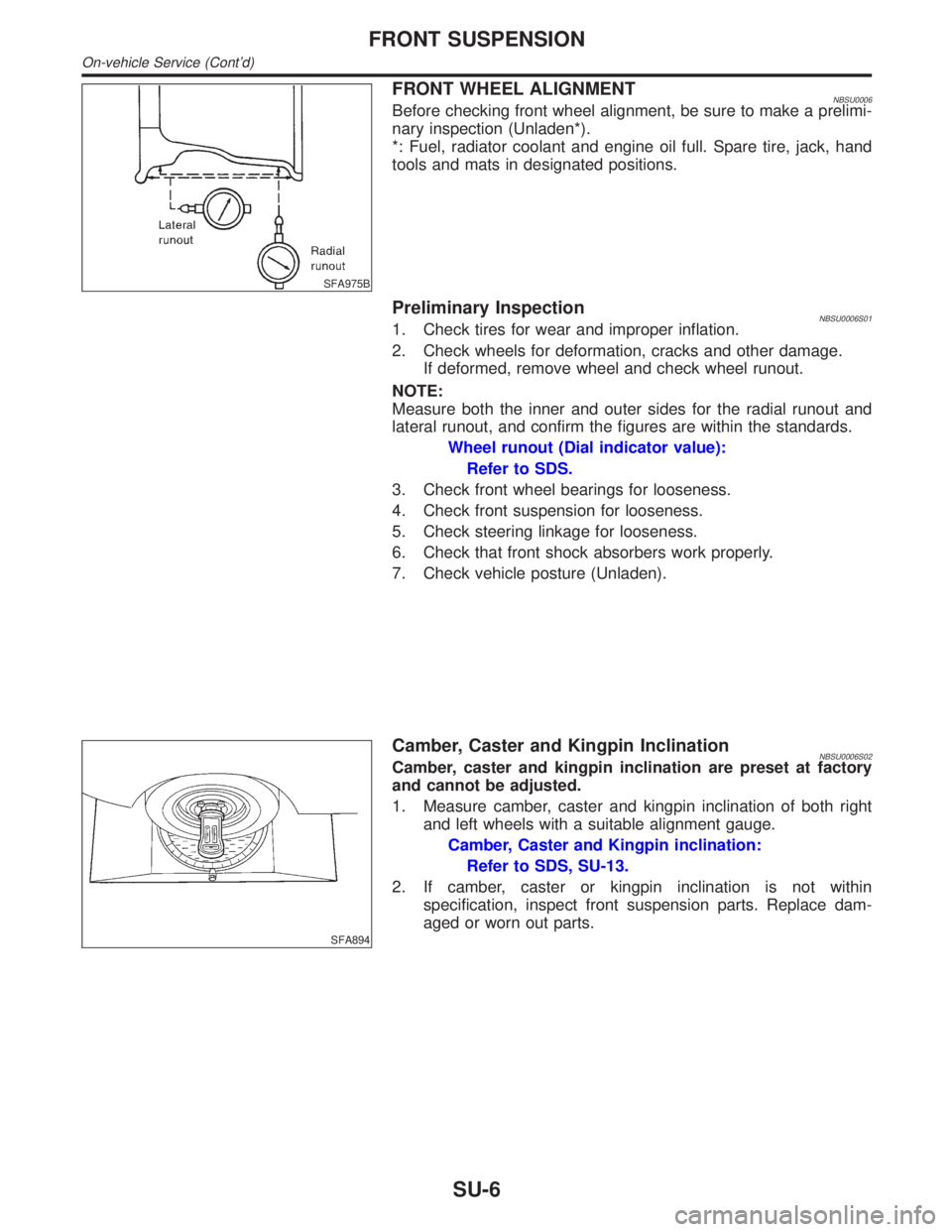
FRONT WHEEL ALIGNMENTNBSU0006Before checking front wheel alignment, be sure to make a prelimi-
nary inspection (Unladen*).
*: Fuel, radiator coolant and engine oil full. Spare tire, jack, hand
tools and mats in designated positions.
Preliminary InspectionNBSU0006S011. Check tires for wear and improper inflation.
2. Check wheels for deformation, cracks and other damage.
If deformed, remove wheel and check wheel runout.
NOTE:
Measure both the inner and outer sides for the radial runout and
lateral runout, and confirm the figures are within the standards.
Wheel runout (Dial indicator value):
Refer to SDS.
3. Check front wheel bearings for looseness.
4. Check front suspension for looseness.
5. Check steering linkage for looseness.
6. Check that front shock absorbers work properly.
7. Check vehicle posture (Unladen).
SFA894
Camber, Caster and Kingpin InclinationNBSU0006S02Camber, caster and kingpin inclination are preset at factory
and cannot be adjusted.
1. Measure camber, caster and kingpin inclination of both right
and left wheels with a suitable alignment gauge.
Camber, Caster and Kingpin inclination:
Refer to SDS, SU-13.
2. If camber, caster or kingpin inclination is not within
specification, inspect front suspension parts. Replace dam-
aged or worn out parts.
FRONT SUSPENSION
On-vehicle Service (Cont'd)
SU-6
Page 2222 of 2395
SFA614B
SFA234AC
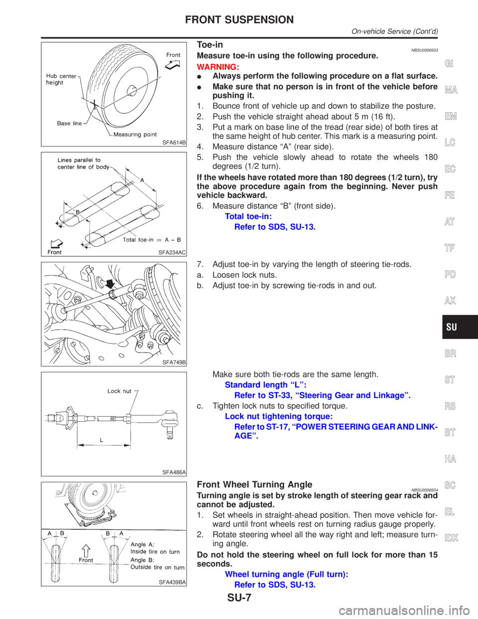
Toe-inNBSU0006S03Measure toe-in using the following procedure.
WARNING:
IAlways perform the following procedure on a flat surface.
IMake sure that no person is in front of the vehicle before
pushing it.
1. Bounce front of vehicle up and down to stabilize the posture.
2. Push the vehicle straight ahead about 5 m (16 ft).
3. Put a mark on base line of the tread (rear side) of both tires at
the same height of hub center. This mark is a measuring point.
4. Measure distance ªAº (rear side).
5. Push the vehicle slowly ahead to rotate the wheels 180
degrees (1/2 turn).
If the wheels have rotated more than 180 degrees (1/2 turn), try
the above procedure again from the beginning. Never push
vehicle backward.
6. Measure distance ªBº (front side).
Total toe-in:
Refer to SDS, SU-13.
SFA749B
7. Adjust toe-in by varying the length of steering tie-rods.
a. Loosen lock nuts.
b. Adjust toe-in by screwing tie-rods in and out.
SFA486A
Make sure both tie-rods are the same length.
Standard length ªLº:
Refer to ST-33, ªSteering Gear and Linkageº.
c. Tighten lock nuts to specified torque.
Lock nut tightening torque:
Refer to ST-17, ªPOWER STEERING GEAR AND LINK-
AGEº.
SFA439BA
Front Wheel Turning AngleNBSU0006S04Turning angle is set by stroke length of steering gear rack and
cannot be adjusted.
1. Set wheels in straight-ahead position. Then move vehicle for-
ward until front wheels rest on turning radius gauge properly.
2. Rotate steering wheel all the way right and left; measure turn-
ing angle.
Do not hold the steering wheel on full lock for more than 15
seconds.
Wheel turning angle (Full turn):
Refer to SDS, SU-13.
GI
MA
EM
LC
EC
FE
AT
TF
PD
AX
BR
ST
RS
BT
HA
SC
EL
IDX
FRONT SUSPENSION
On-vehicle Service (Cont'd)
SU-7