length INFINITI QX4 2001 Factory Service Manual
[x] Cancel search | Manufacturer: INFINITI, Model Year: 2001, Model line: QX4, Model: INFINITI QX4 2001Pages: 2395, PDF Size: 43.2 MB
Page 278 of 2395

SAT359I
Control Valve Assembly and AccumulatorsNBAT0100REMOVALNBAT0100S011. Remove exhaust front tube.
2. Remove oil pan and gasket and drain ATF.
SAT073BA
3. Remove A/T fluid temperature sensor if necessary.
4. Remove oil strainer.
SAT353B
5. Remove control valve assembly by removing fixing bolts and
disconnecting harness connector.
Bolt length and location
Bolt symbolmm (in)
A 33 (1.30)
B 45 (1.77)
6. Remove solenoids and valves from valve body if necessary.
7. Remove terminal cord assembly if necessary.
SAT074BA
8. Remove accumulatorA, B, CandDby applying compressed
air if necessary.
IHold each piston with rag.
9. Reinstall any part removed.
IAlways use new sealing parts.
GI
MA
EM
LC
EC
FE
TF
PD
AX
SU
BR
ST
RS
BT
HA
SC
EL
IDX
ON-VEHICLE SERVICE
Control Valve Assembly and Accumulators
AT-273
Page 284 of 2395

SAT017B
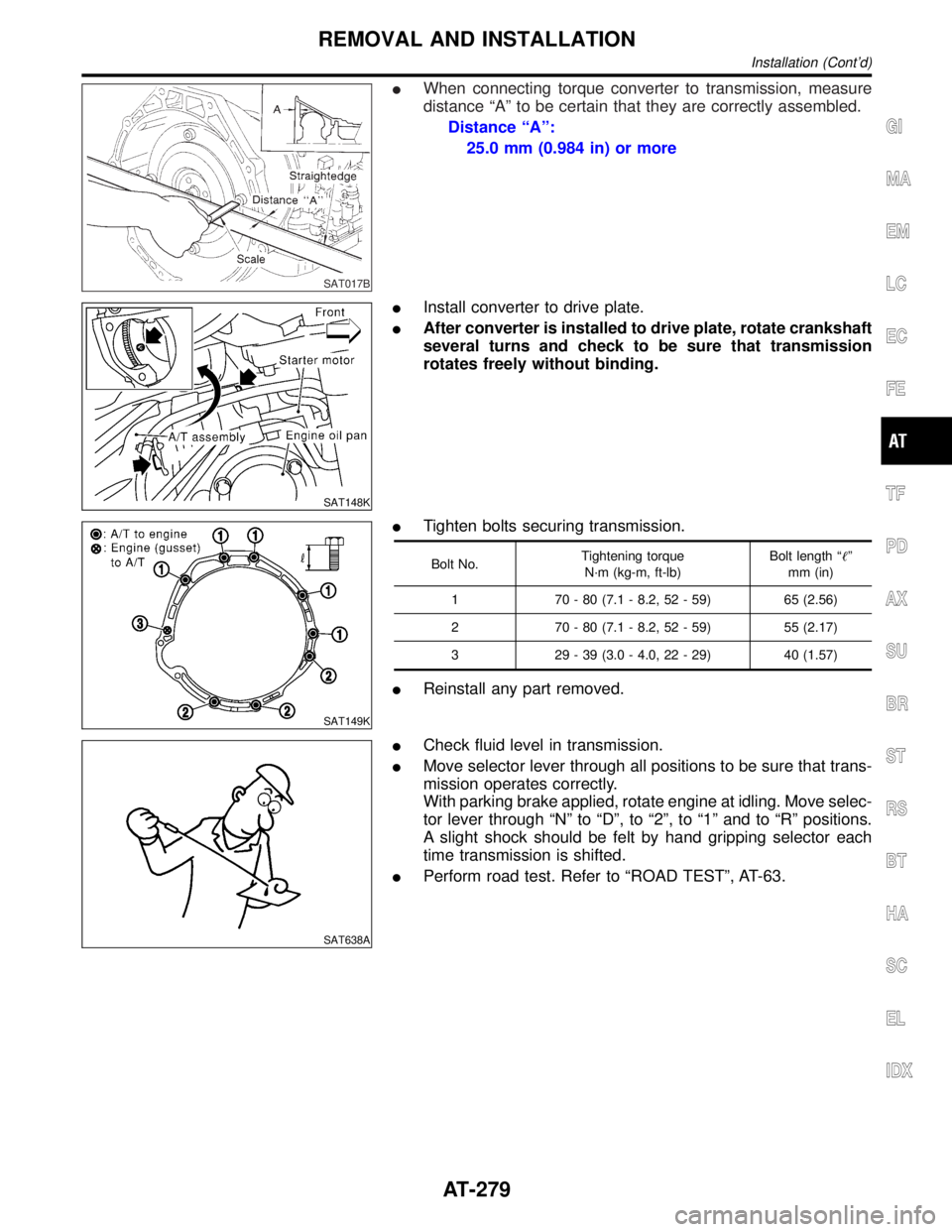
IWhen connecting torque converter to transmission, measure
distance ªAº to be certain that they are correctly assembled.
Distance ªAº:
25.0 mm (0.984 in) or more
SAT148K
IInstall converter to drive plate.
IAfter converter is installed to drive plate, rotate crankshaft
several turns and check to be sure that transmission
rotates freely without binding.
SAT149K
ITighten bolts securing transmission.
Bolt No.Tightening torque
N´m (kg-m, ft-lb)Bolt length ªº
mm (in)
1 70 - 80 (7.1 - 8.2, 52 - 59) 65 (2.56)
2 70 - 80 (7.1 - 8.2, 52 - 59) 55 (2.17)
3 29 - 39 (3.0 - 4.0, 22 - 29) 40 (1.57)
IReinstall any part removed.
SAT638A
ICheck fluid level in transmission.
IMove selector lever through all positions to be sure that trans-
mission operates correctly.
With parking brake applied, rotate engine at idling. Move selec-
tor lever through ªNº to ªDº, to ª2º, to ª1º and to ªRº positions.
A slight shock should be felt by hand gripping selector each
time transmission is shifted.
IPerform road test. Refer to ªROAD TESTº, AT-63.
GI
MA
EM
LC
EC
FE
TF
PD
AX
SU
BR
ST
RS
BT
HA
SC
EL
IDX
REMOVAL AND INSTALLATION
Installation (Cont'd)
AT-279
Page 293 of 2395

SAT353B
b. Remove bolts A and B, and remove control valve assembly
from transmission.
Bolt symbol Length mm (in)
A 33 (1.30)
B 45 (1.77)
SAT026B
c. Remove solenoid connector.
IBe careful not to damage connector.
SAT127B
d. Remove manual valve from control valve assembly.
SAT128B
12. Remove terminal cord assembly from transmission case while
pushing on stopper.
IBe careful not to damage cord.
IDo not remove terminal cord assembly unless it is dam-
aged.
DISASSEMBLY
AT-288
Page 311 of 2395

SAT199BA
g. Install and temporarily tighten bolts and tube brackets in their
proper locations.
Bolt length and location:
Bolt symbol a b c d
Bolt length mm (in) 70 (2.76) 50 (1.97) 33 (1.30) 27 (1.06)
SAT200B
2. Install solenoids.
a. Attach O-ring and install torque converter clutch solenoid valve
and side plates onto lower body.
SAT150G
b. Attach O-rings and install 3-unit solenoids assembly onto
upper body.
c. Attach O-ring and install line pressure solenoid valve onto
upper body.
3. Tighten all bolts.
REPAIR FOR COMPONENT PARTS
Control Valve Assembly (Cont'd)
AT-306
Page 314 of 2395

SAT826A
b. Remove retainer plates while holding spring.
SAT827A
c. Place mating surface of valve facedown, and remove internal
parts.
IIf a valve is hard to remove, lightly tap valve body with a
soft hammer.
IBe careful not to drop or damage valves, sleeves, etc.
SAT828A
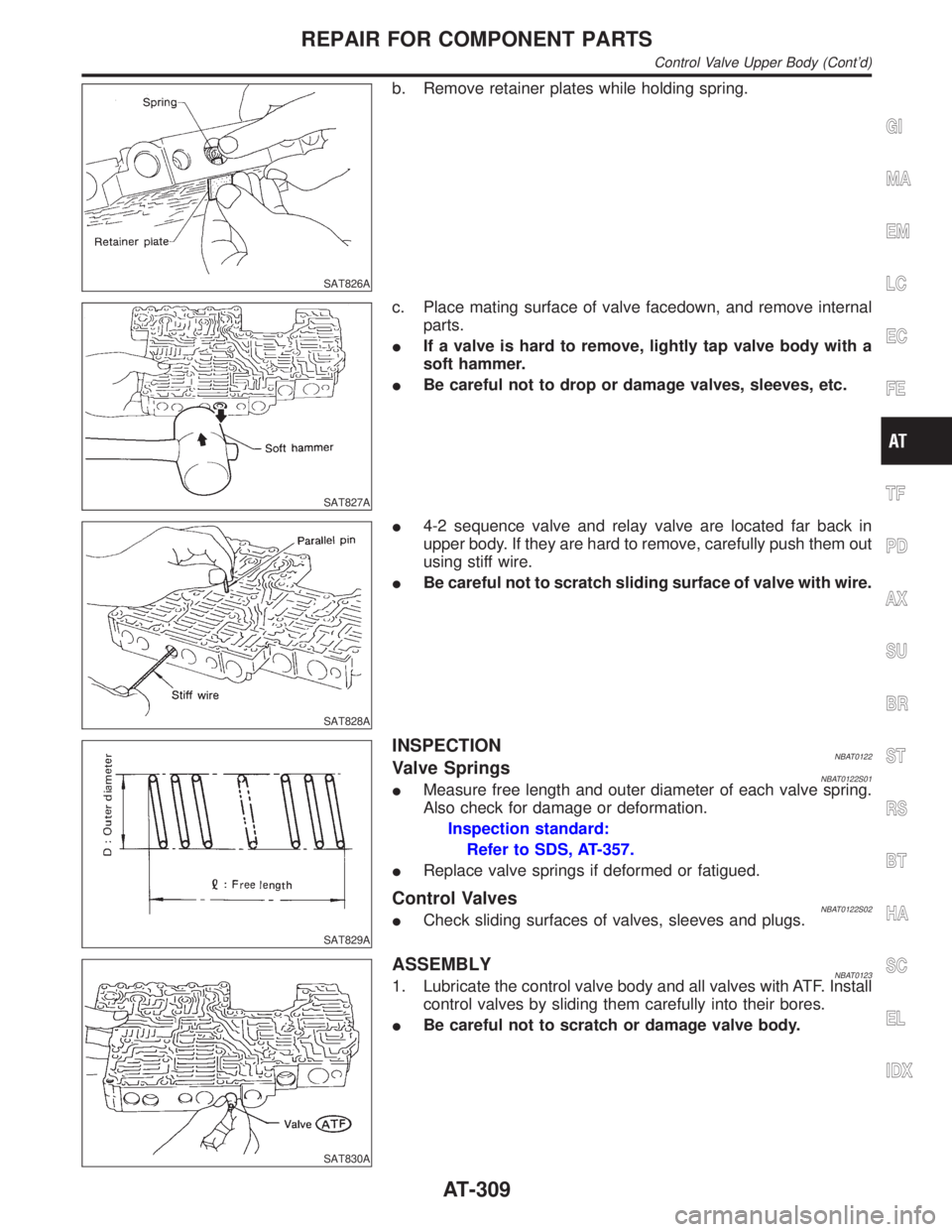
I4-2 sequence valve and relay valve are located far back in
upper body. If they are hard to remove, carefully push them out
using stiff wire.
IBe careful not to scratch sliding surface of valve with wire.
SAT829A
INSPECTIONNBAT0122Valve SpringsNBAT0122S01IMeasure free length and outer diameter of each valve spring.
Also check for damage or deformation.
Inspection standard:
Refer to SDS, AT-357.
IReplace valve springs if deformed or fatigued.
Control ValvesNBAT0122S02ICheck sliding surfaces of valves, sleeves and plugs.
SAT830A
ASSEMBLYNBAT01231. Lubricate the control valve body and all valves with ATF. Install
control valves by sliding them carefully into their bores.
IBe careful not to scratch or damage valve body.
GI
MA
EM
LC
EC
FE
TF
PD
AX
SU
BR
ST
RS
BT
HA
SC
EL
IDX
REPAIR FOR COMPONENT PARTS
Control Valve Upper Body (Cont'd)
AT-309
Page 318 of 2395

SAT838A
DISASSEMBLYNBAT01251. Remove valves at parallel pins.
2. Remove valves at retainer plates.
For removal procedures, refer to ªDISASSEMBLYº of Control
Valve Upper Body.
SAT829A
INSPECTIONNBAT0126Valve SpringsNBAT0126S01ICheck each valve spring for damage or deformation. Also
measure free length and outer diameter.
Inspection standard:
Refer to SDS, AT-357.
IReplace valve springs if deformed or fatigued.
Control ValvesNBAT0126S02ICheck sliding surfaces of control valves, sleeves and plugs for
damage.
SAT838A
ASSEMBLYNBAT0127IInstall control valves.
For installation procedures, refer to ªASSEMBLYº of Control
Valve Upper Body, AT-309.
GI
MA
EM
LC
EC
FE
TF
PD
AX
SU
BR
ST
RS
BT
HA
SC
EL
IDX
REPAIR FOR COMPONENT PARTS
Control Valve Lower Body (Cont'd)
AT-313
Page 330 of 2395

SAT382I
3. Remove low one-way clutch inner race, spring retainer and
return spring from transmission case.
4. Remove seal rings from low one-way clutch inner race.
5. Remove needle bearing from low one-way clutch inner race.
SAT876A
6. Remove low and reverse brake piston using compressed air.
7. Remove oil seal and D-ring from piston.
INSPECTIONNBAT0138Low and Reverse Brake Snap Ring and Spring RetainerNBAT0138S01ICheck for deformation, or damage.
SAT829A
Low and Reverse Brake Return SpringsNBAT0138S02ICheck for deformation or damage. Also measure free length
and outside diameter.
Inspection standard:
Refer to SDS, AT-357.
SAT845A
Low and Reverse Brake Drive PlatesNBAT0138S03ICheck facing for burns, cracks or damage.
IMeasure thickness of facing.
Thickness of drive plate:
Standard value
Model 4EX16 (2WD)
1.90 - 2.05 mm (0.075 - 0.081 in)
Model 4EX17, 4EX23 (4WD)
1.52 - 1.67 mm (0.0598 - 0.0657 in)
Wear limit
GI
MA
EM
LC
EC
FE
TF
PD
AX
SU
BR
ST
RS
BT
HA
SC
EL
IDX
REPAIR FOR COMPONENT PARTS
Low & Reverse Brake (Cont'd)
AT-325
Page 340 of 2395

SAT162K
Return SpringsNBAT0150S02ICheck for deformation or damage. Measure free length and
outer diameter.
Inspection standard:
Refer to SDS, AT-357.
SAT917A
ASSEMBLYNBAT01511. Install O-rings onto servo piston retainer.
IApply ATF to O-rings.
IPay attention to position of each O-ring.
SAT918A
2. Install servo cushion spring retainer onto band servo piston.
SAT919A
3. Install E-ring onto servo cushion spring retainer.
SAT920A
4. Install D-rings onto band servo piston.
IApply ATF to D-rings.
GI
MA
EM
LC
EC
FE
TF
PD
AX
SU
BR
ST
RS
BT
HA
SC
EL
IDX
REPAIR FOR COMPONENT PARTS
Band Servo Piston Assembly (Cont'd)
AT-335
Page 345 of 2395

SAT523GA
2. Install accumulator piston.
a. Install O-rings onto accumulator piston.
IApply ATF to O-rings.
Accumulator piston O-rings
Unit: mm (in)
Accumulator A B C D
Small diameter end 29 (1.14) 32 (1.26) 45 (1.77) 29 (1.14)
Large diameter end 45 (1.77) 50 (1.97) 50 (1.97) 45 (1.77)
SAT938A
b. Install return spring for accumulator A onto transmission case.
Free length of return spring:
Refer to SDS, AT-357.
SAT939AA
c. Install accumulator pistons A, B, C and D.
IApply ATF to transmission case.
SAT941A
3. Install band servo piston.
a. Install return springs onto servo piston.
SAT942A
b. Install band servo piston onto transmission case.
IApply ATF to O-ring of band servo piston and transmis-
sion case.
c. Install gasket for band servo onto transmission case.
ASSEMBLY
Assembly (1) (Cont'd)
AT-340
Page 357 of 2395

SAT001B
7. Install turbine revolution sensor.
8. Adjust brake band.
a. Tighten anchor end bolt to specified torque.
Anchor end bolt:
:4-6N´m(0.4 - 0.6 kg-m, 35 - 52 in-lb)
b. Back off anchor end bolt two and a half turns.
SAT002B
c. While holding anchor end bolt, tighten lock nut.
Ancher end bolt nut:
: 41 - 50 N´m (4.1 - 5.2 kg-m, 30 - 37 ft-lb)
SAT115B
9. Install terminal cord assembly.
a. Install O-ring on terminal cord assembly.
IApply petroleum jelly to O-ring.
b. Compress terminal cord assembly stopper and install terminal
cord assembly on transmission case.
SAT004BA
10. Install control valve assembly.
a. Install accumulator piston return springs B, C and D.
Free length of return springs:
Refer to SDS, AT-357.
SAT005B
b. Install manual valve on control valve.
IApply ATF to manual valve.
ASSEMBLY
Assembly (2) (Cont'd)
AT-352