charging INFINITI QX4 2001 Factory Service Manual
[x] Cancel search | Manufacturer: INFINITI, Model Year: 2001, Model line: QX4, Model: INFINITI QX4 2001Pages: 2395, PDF Size: 43.2 MB
Page 96 of 2395
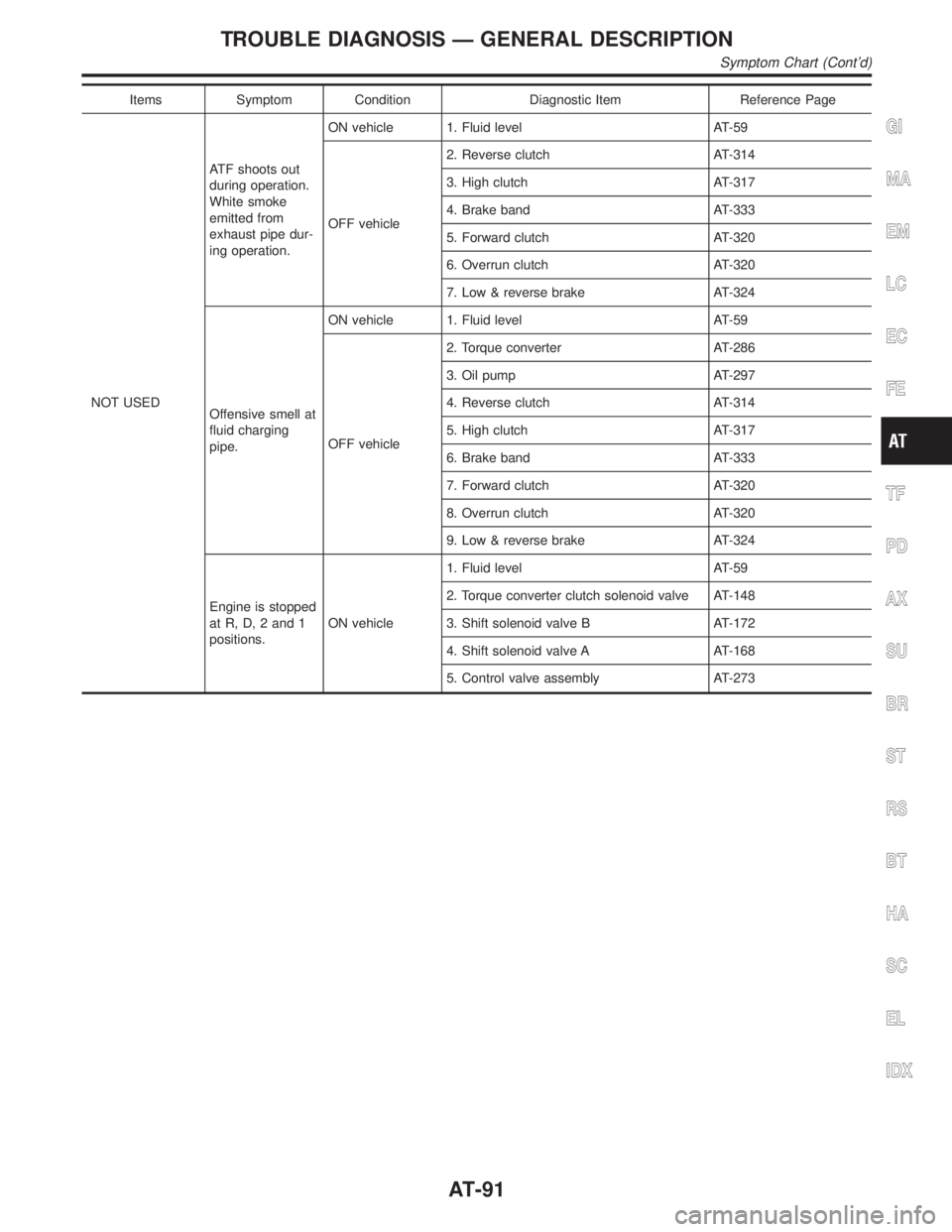
Items Symptom Condition Diagnostic Item Reference Page
NOT USEDATF shoots out
during operation.
White smoke
emitted from
exhaust pipe dur-
ing operation.ON vehicle 1. Fluid level AT-59
OFF vehicle2. Reverse clutch AT-314
3. High clutch AT-317
4. Brake band AT-333
5. Forward clutch AT-320
6. Overrun clutch AT-320
7. Low & reverse brake AT-324
Offensive smell at
fluid charging
pipe.ON vehicle 1. Fluid level AT-59
OFF vehicle2. Torque converter AT-286
3. Oil pump AT-297
4. Reverse clutch AT-314
5. High clutch AT-317
6. Brake band AT-333
7. Forward clutch AT-320
8. Overrun clutch AT-320
9. Low & reverse brake AT-324
Engine is stopped
at R, D, 2 and 1
positions.ON vehicle1. Fluid level AT-59
2. Torque converter clutch solenoid valve AT-148
3. Shift solenoid valve B AT-172
4. Shift solenoid valve A AT-168
5. Control valve assembly AT-273
GI
MA
EM
LC
EC
FE
TF
PD
AX
SU
BR
ST
RS
BT
HA
SC
EL
IDX
TROUBLE DIAGNOSIS Ð GENERAL DESCRIPTION
Symptom Chart (Cont'd)
AT-91
Page 282 of 2395
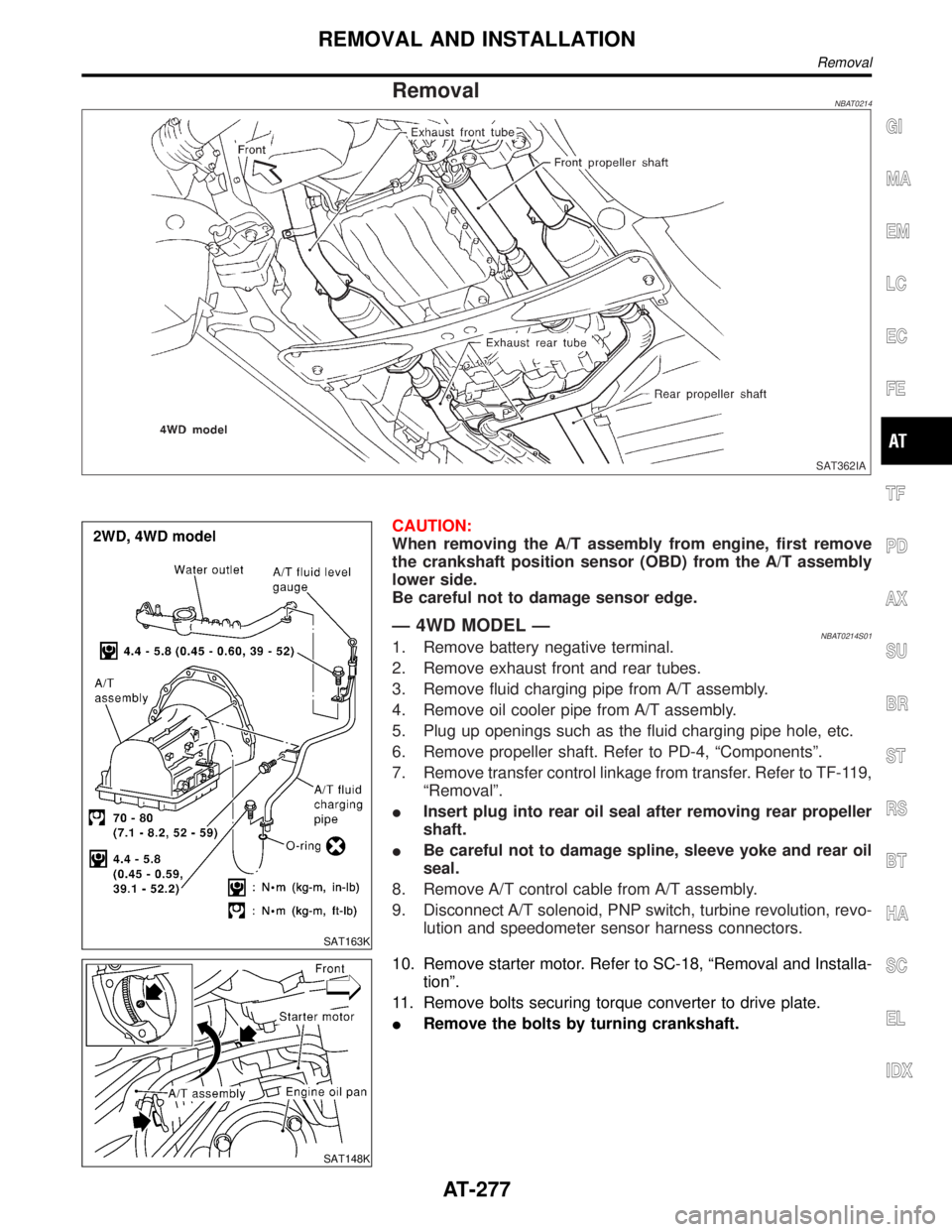
RemovalNBAT0214
SAT362IA
SAT163K
CAUTION:
When removing the A/T assembly from engine, first remove
the crankshaft position sensor (OBD) from the A/T assembly
lower side.
Be careful not to damage sensor edge.
Ð 4WD MODEL ÐNBAT0214S011. Remove battery negative terminal.
2. Remove exhaust front and rear tubes.
3. Remove fluid charging pipe from A/T assembly.
4. Remove oil cooler pipe from A/T assembly.
5. Plug up openings such as the fluid charging pipe hole, etc.
6. Remove propeller shaft. Refer to PD-4, ªComponentsº.
7. Remove transfer control linkage from transfer. Refer to TF-119,
ªRemovalº.
IInsert plug into rear oil seal after removing rear propeller
shaft.
IBe careful not to damage spline, sleeve yoke and rear oil
seal.
8. Remove A/T control cable from A/T assembly.
9. Disconnect A/T solenoid, PNP switch, turbine revolution, revo-
lution and speedometer sensor harness connectors.
SAT148K
10. Remove starter motor. Refer to SC-18, ªRemoval and Installa-
tionº.
11. Remove bolts securing torque converter to drive plate.
IRemove the bolts by turning crankshaft.
GI
MA
EM
LC
EC
FE
TF
PD
AX
SU
BR
ST
RS
BT
HA
SC
EL
IDX
REMOVAL AND INSTALLATION
Removal
AT-277
Page 283 of 2395
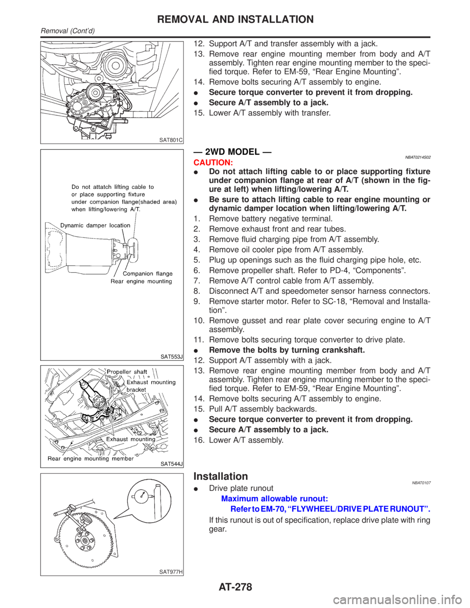
SAT801C
12. Support A/T and transfer assembly with a jack.
13. Remove rear engine mounting member from body and A/T
assembly. Tighten rear engine mounting member to the speci-
fied torque. Refer to EM-59, ªRear Engine Mountingº.
14. Remove bolts securing A/T assembly to engine.
ISecure torque converter to prevent it from dropping.
ISecure A/T assembly to a jack.
15. Lower A/T assembly with transfer.
SAT553J
SAT544J
Ð 2WD MODEL ÐNBAT0214S02CAUTION:
IDo not attach lifting cable to or place supporting fixture
under companion flange at rear of A/T (shown in the fig-
ure at left) when lifting/lowering A/T.
IBe sure to attach lifting cable to rear engine mounting or
dynamic damper location when lifting/lowering A/T.
1. Remove battery negative terminal.
2. Remove exhaust front and rear tubes.
3. Remove fluid charging pipe from A/T assembly.
4. Remove oil cooler pipe from A/T assembly.
5. Plug up openings such as the fluid charging pipe hole, etc.
6. Remove propeller shaft. Refer to PD-4, ªComponentsº.
7. Remove A/T control cable from A/T assembly.
8. Disconnect A/T and speedometer sensor harness connectors.
9. Remove starter motor. Refer to SC-18, ªRemoval and Installa-
tionº.
10. Remove gusset and rear plate cover securing engine to A/T
assembly.
11. Remove bolts securing torque converter to drive plate.
IRemove the bolts by turning crankshaft.
12. Support A/T assembly with a jack.
13. Remove rear engine mounting member from body and A/T
assembly. Tighten rear engine mounting member to the speci-
fied torque. Refer to EM-59, ªRear Engine Mountingº.
14. Remove bolts securing A/T assembly to engine.
15. Pull A/T assembly backwards.
ISecure torque converter to prevent it from dropping.
ISecure A/T assembly to a jack.
16. Lower A/T assembly.
SAT977H
InstallationNBAT0107IDrive plate runout
Maximum allowable runout:
Refer to EM-70, ªFLYWHEEL/DRIVE PLATE RUNOUTº.
If this runout is out of specification, replace drive plate with ring
gear.
REMOVAL AND INSTALLATION
Removal (Cont'd)
AT-278
Page 1160 of 2395
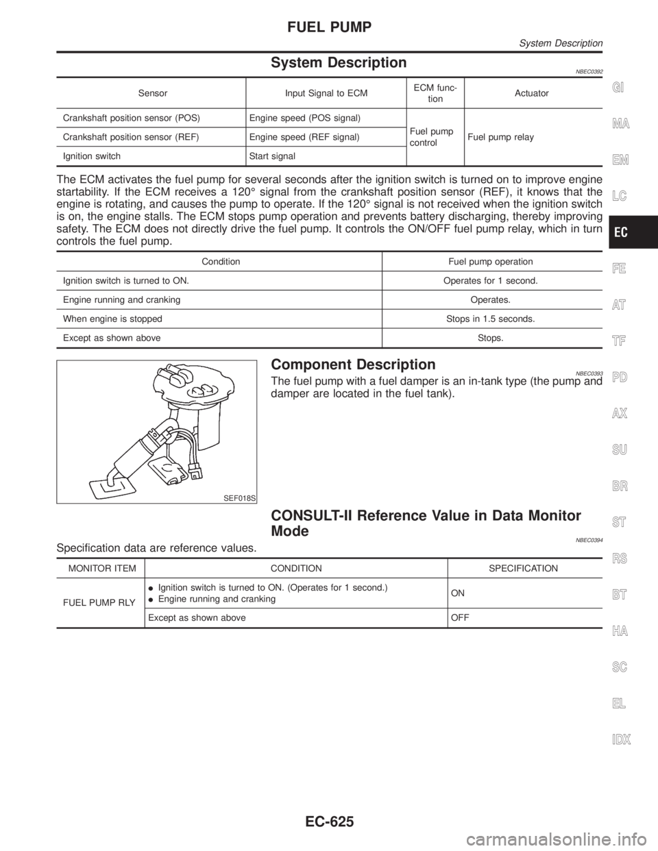
System DescriptionNBEC0392
Sensor Input Signal to ECMECM func-
tionActuator
Crankshaft position sensor (POS) Engine speed (POS signal)
Fuel pump
controlFuel pump relay Crankshaft position sensor (REF) Engine speed (REF signal)
Ignition switch Start signal
The ECM activates the fuel pump for several seconds after the ignition switch is turned on to improve engine
startability. If the ECM receives a 120É signal from the crankshaft position sensor (REF), it knows that the
engine is rotating, and causes the pump to operate. If the 120É signal is not received when the ignition switch
is on, the engine stalls. The ECM stops pump operation and prevents battery discharging, thereby improving
safety. The ECM does not directly drive the fuel pump. It controls the ON/OFF fuel pump relay, which in turn
controls the fuel pump.
Condition Fuel pump operation
Ignition switch is turned to ON. Operates for 1 second.
Engine running and cranking Operates.
When engine is stopped Stops in 1.5 seconds.
Except as shown aboveStops.
SEF018S
Component DescriptionNBEC0393The fuel pump with a fuel damper is an in-tank type (the pump and
damper are located in the fuel tank).
CONSULT-II Reference Value in Data Monitor
Mode
NBEC0394Specification data are reference values.
MONITOR ITEM CONDITION SPECIFICATION
FUEL PUMP RLYIIgnition switch is turned to ON. (Operates for 1 second.)
IEngine running and crankingON
Except as shown above OFF
GI
MA
EM
LC
FE
AT
TF
PD
AX
SU
BR
ST
RS
BT
HA
SC
EL
IDX
FUEL PUMP
System Description
EC-625
Page 1642 of 2395
NBEL0145
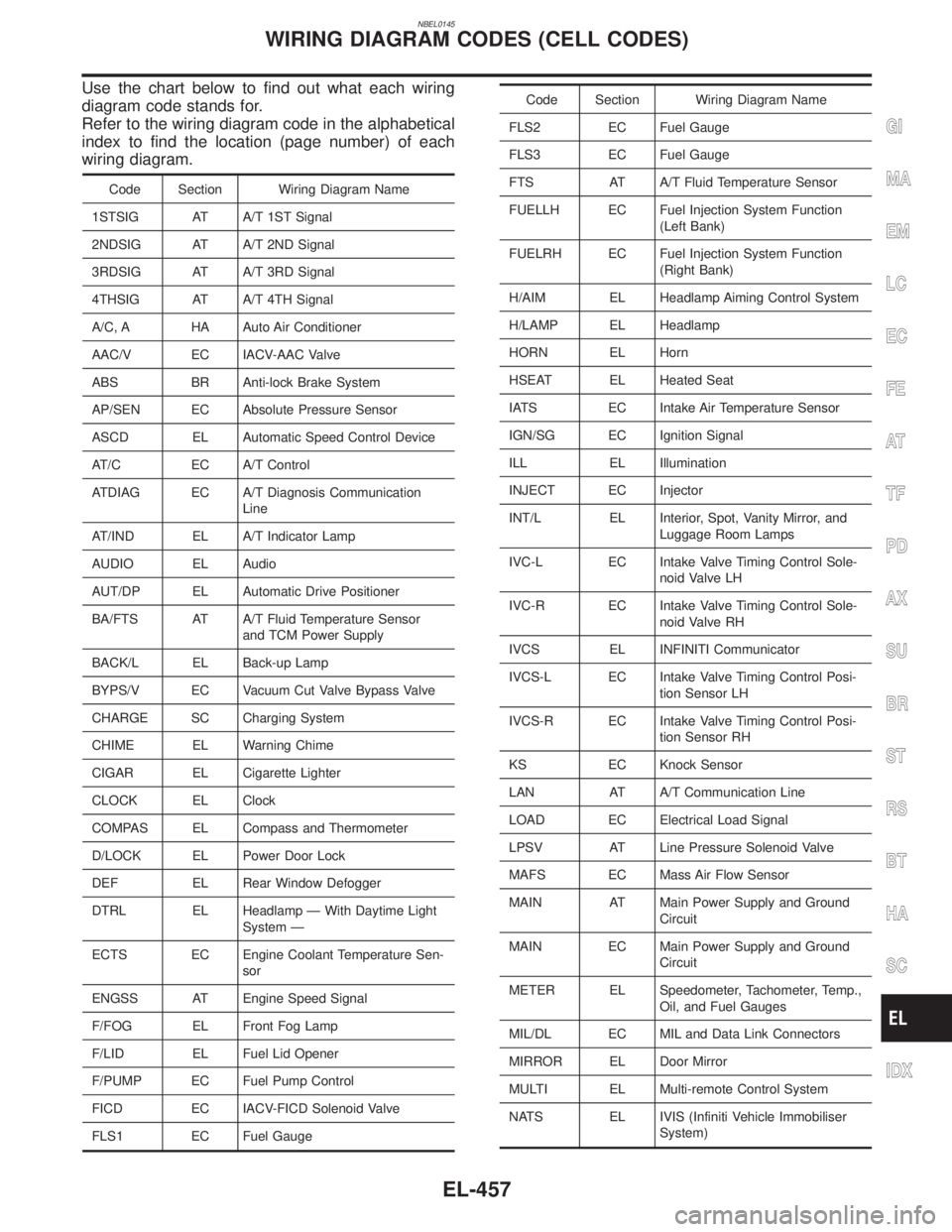
Use the chart below to find out what each wiring
diagram code stands for.
Refer to the wiring diagram code in the alphabetical
index to find the location (page number) of each
wiring diagram.
Code Section Wiring Diagram Name
1STSIG AT A/T 1ST Signal
2NDSIG AT A/T 2ND Signal
3RDSIG AT A/T 3RD Signal
4THSIG AT A/T 4TH Signal
A/C, A HA Auto Air Conditioner
AAC/V EC IACV-AAC Valve
ABS BR Anti-lock Brake System
AP/SEN EC Absolute Pressure Sensor
ASCD EL Automatic Speed Control Device
AT/C EC A/T Control
ATDIAG EC A/T Diagnosis Communication
Line
AT/IND EL A/T Indicator Lamp
AUDIO EL Audio
AUT/DP EL Automatic Drive Positioner
BA/FTS AT A/T Fluid Temperature Sensor
and TCM Power Supply
BACK/L EL Back-up Lamp
BYPS/V EC Vacuum Cut Valve Bypass Valve
CHARGE SC Charging System
CHIME EL Warning Chime
CIGAR EL Cigarette Lighter
CLOCK EL Clock
COMPAS EL Compass and Thermometer
D/LOCK EL Power Door Lock
DEF EL Rear Window Defogger
DTRL EL Headlamp Ð With Daytime Light
System Ð
ECTS EC Engine Coolant Temperature Sen-
sor
ENGSS AT Engine Speed Signal
F/FOG EL Front Fog Lamp
F/LID EL Fuel Lid Opener
F/PUMP EC Fuel Pump Control
FICD EC IACV-FICD Solenoid Valve
FLS1 EC Fuel Gauge
Code Section Wiring Diagram Name
FLS2 EC Fuel Gauge
FLS3 EC Fuel Gauge
FTS AT A/T Fluid Temperature Sensor
FUELLH EC Fuel Injection System Function
(Left Bank)
FUELRH EC Fuel Injection System Function
(Right Bank)
H/AIM EL Headlamp Aiming Control System
H/LAMP EL Headlamp
HORN EL Horn
HSEAT EL Heated Seat
IATS EC Intake Air Temperature Sensor
IGN/SG EC Ignition Signal
ILL EL Illumination
INJECT EC Injector
INT/L EL Interior, Spot, Vanity Mirror, and
Luggage Room Lamps
IVC-L EC Intake Valve Timing Control Sole-
noid Valve LH
IVC-R EC Intake Valve Timing Control Sole-
noid Valve RH
IVCS EL INFINITI Communicator
IVCS-L EC Intake Valve Timing Control Posi-
tion Sensor LH
IVCS-R EC Intake Valve Timing Control Posi-
tion Sensor RH
KS EC Knock Sensor
LAN AT A/T Communication Line
LOAD EC Electrical Load Signal
LPSV AT Line Pressure Solenoid Valve
MAFS EC Mass Air Flow Sensor
MAIN AT Main Power Supply and Ground
Circuit
MAIN EC Main Power Supply and Ground
Circuit
METER EL Speedometer, Tachometer, Temp.,
Oil, and Fuel Gauges
MIL/DL EC MIL and Data Link Connectors
MIRROR EL Door Mirror
MULTI EL Multi-remote Control System
NATS EL IVIS (Infiniti Vehicle Immobiliser
System)
GI
MA
EM
LC
EC
FE
AT
TF
PD
AX
SU
BR
ST
RS
BT
HA
SC
IDX
WIRING DIAGRAM CODES (CELL CODES)
EL-457
Page 1801 of 2395
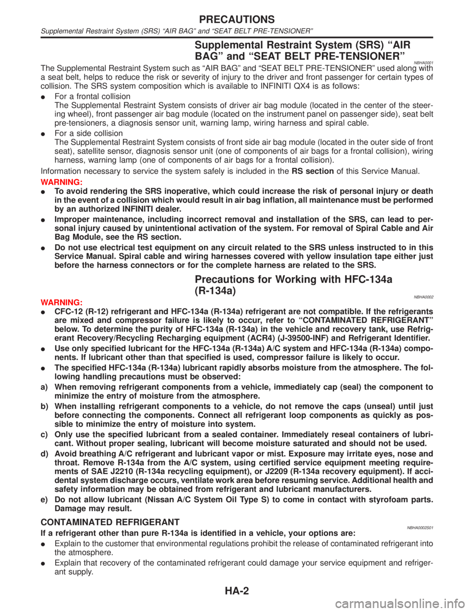
Supplemental Restraint System (SRS) ªAIR
BAGº and ªSEAT BELT PRE-TENSIONERº
NBHA0001The Supplemental Restraint System such as ªAIR BAGº and ªSEAT BELT PRE-TENSIONERº used along with
a seat belt, helps to reduce the risk or severity of injury to the driver and front passenger for certain types of
collision. The SRS system composition which is available to INFINITI QX4 is as follows:
IFor a frontal collision
The Supplemental Restraint System consists of driver air bag module (located in the center of the steer-
ing wheel), front passenger air bag module (located on the instrument panel on passenger side), seat belt
pre-tensioners, a diagnosis sensor unit, warning lamp, wiring harness and spiral cable.
IFor a side collision
The Supplemental Restraint System consists of front side air bag module (located in the outer side of front
seat), satellite sensor, diagnosis sensor unit (one of components of air bags for a frontal collision), wiring
harness, warning lamp (one of components of air bags for a frontal collision).
Information necessary to service the system safely is included in theRS sectionof this Service Manual.
WARNING:
ITo avoid rendering the SRS inoperative, which could increase the risk of personal injury or death
in the event of a collision which would result in air bag inflation, all maintenance must be performed
by an authorized INFINITI dealer.
IImproper maintenance, including incorrect removal and installation of the SRS, can lead to per-
sonal injury caused by unintentional activation of the system. For removal of Spiral Cable and Air
Bag Module, see the RS section.
IDo not use electrical test equipment on any circuit related to the SRS unless instructed to in this
Service Manual. Spiral cable and wiring harnesses covered with yellow insulation tape either just
before the harness connectors or for the complete harness are related to the SRS.
Precautions for Working with HFC-134a
(R-134a)
NBHA0002WARNING:
ICFC-12 (R-12) refrigerant and HFC-134a (R-134a) refrigerant are not compatible. If the refrigerants
are mixed and compressor failure is likely to occur, refer to ªCONTAMINATED REFRIGERANTº
below. To determine the purity of HFC-134a (R-134a) in the vehicle and recovery tank, use Refrig-
erant Recovery/Recycling Recharging equipment (ACR4) (J-39500-INF) and Refrigerant Identifier.
IUse only specified lubricant for the HFC-134a (R-134a) A/C system and HFC-134a (R-134a) compo-
nents. If lubricant other than that specified is used, compressor failure is likely to occur.
IThe specified HFC-134a (R-134a) lubricant rapidly absorbs moisture from the atmosphere. The fol-
lowing handling precautions must be observed:
a) When removing refrigerant components from a vehicle, immediately cap (seal) the component to
minimize the entry of moisture from the atmosphere.
b) When installing refrigerant components to a vehicle, do not remove the caps (unseal) until just
before connecting the components. Connect all refrigerant loop components as quickly as pos-
sible to minimize the entry of moisture into system.
c) Only use the specified lubricant from a sealed container. Immediately reseal containers of lubri-
cant. Without proper sealing, lubricant will become moisture saturated and should not be used.
d) Avoid breathing A/C refrigerant and lubricant vapor or mist. Exposure may irritate eyes, nose and
throat. Remove R-134a from the A/C system, using certified service equipment meeting require-
ments of SAE J2210 (R-134a recycling equipment), or J2209 (R-134a recovery equipment). If acci-
dental system discharge occurs, ventilate work area before resuming service. Additional health and
safety information may be obtained from refrigerant and lubricant manufacturers.
e) Do not allow lubricant (Nissan A/C System Oil Type S) to come in contact with styrofoam parts.
Damage may result.
CONTAMINATED REFRIGERANTNBHA0002S01If a refrigerant other than pure R-134a is identified in a vehicle, your options are:
IExplain to the customer that environmental regulations prohibit the release of contaminated refrigerant into
the atmosphere.
IExplain that recovery of the contaminated refrigerant could damage your service equipment and refriger-
ant supply.
PRECAUTIONS
Supplemental Restraint System (SRS) ªAIR BAGº and ªSEAT BELT PRE-TENSIONERº
HA-2
Page 1805 of 2395
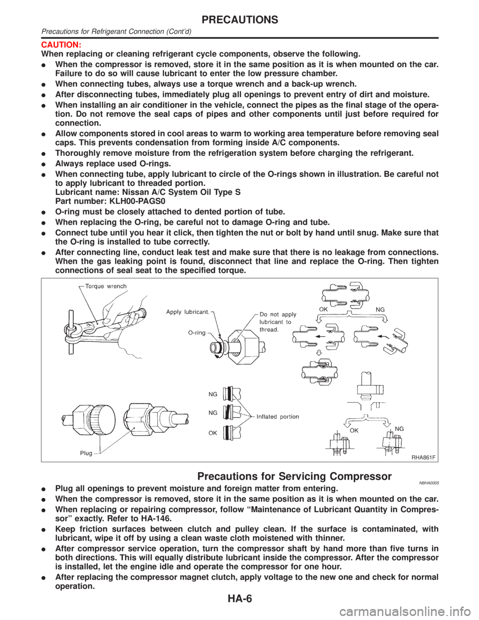
CAUTION:
When replacing or cleaning refrigerant cycle components, observe the following.
IWhen the compressor is removed, store it in the same position as it is when mounted on the car.
Failure to do so will cause lubricant to enter the low pressure chamber.
IWhen connecting tubes, always use a torque wrench and a back-up wrench.
IAfter disconnecting tubes, immediately plug all openings to prevent entry of dirt and moisture.
IWhen installing an air conditioner in the vehicle, connect the pipes as the final stage of the opera-
tion. Do not remove the seal caps of pipes and other components until just before required for
connection.
IAllow components stored in cool areas to warm to working area temperature before removing seal
caps. This prevents condensation from forming inside A/C components.
IThoroughly remove moisture from the refrigeration system before charging the refrigerant.
IAlways replace used O-rings.
IWhen connecting tube, apply lubricant to circle of the O-rings shown in illustration. Be careful not
to apply lubricant to threaded portion.
Lubricant name: Nissan A/C System Oil Type S
Part number: KLH00-PAGS0
IO-ring must be closely attached to dented portion of tube.
IWhen replacing the O-ring, be careful not to damage O-ring and tube.
IConnect tube until you hear it click, then tighten the nut or bolt by hand until snug. Make sure that
the O-ring is installed to tube correctly.
IAfter connecting line, conduct leak test and make sure that there is no leakage from connections.
When the gas leaking point is found, disconnect that line and replace the O-ring. Then tighten
connections of seal seat to the specified torque.
RHA861F
Precautions for Servicing CompressorNBHA0005IPlug all openings to prevent moisture and foreign matter from entering.
IWhen the compressor is removed, store it in the same position as it is when mounted on the car.
IWhen replacing or repairing compressor, follow ªMaintenance of Lubricant Quantity in Compres-
sorº exactly. Refer to HA-146.
IKeep friction surfaces between clutch and pulley clean. If the surface is contaminated, with
lubricant, wipe it off by using a clean waste cloth moistened with thinner.
IAfter compressor service operation, turn the compressor shaft by hand more than five turns in
both directions. This will equally distribute lubricant inside the compressor. After the compressor
is installed, let the engine idle and operate the compressor for one hour.
IAfter replacing the compressor magnet clutch, apply voltage to the new one and check for normal
operation.
PRECAUTIONS
Precautions for Refrigerant Connection (Cont'd)
HA-6
Page 1807 of 2395
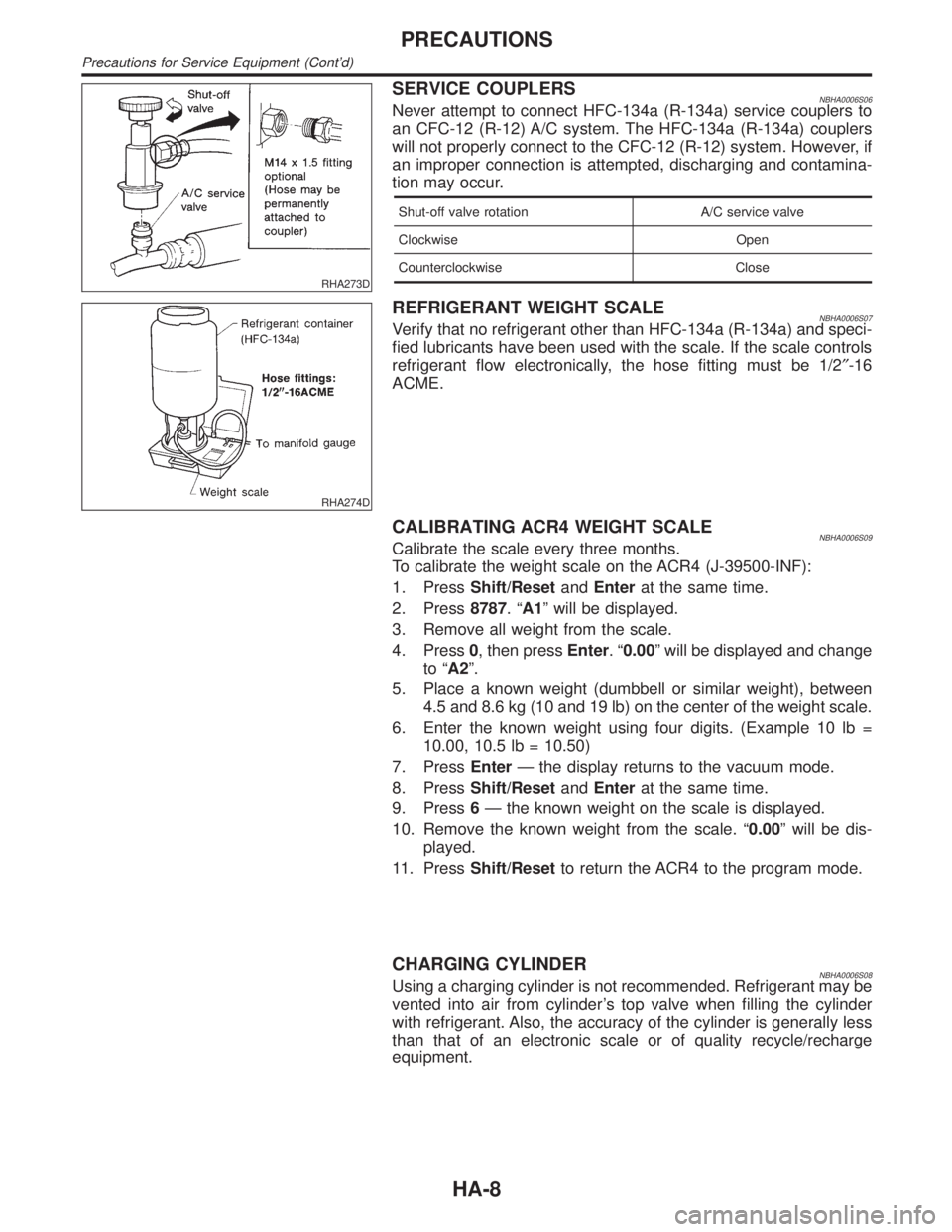
RHA273D
SERVICE COUPLERSNBHA0006S06Never attempt to connect HFC-134a (R-134a) service couplers to
an CFC-12 (R-12) A/C system. The HFC-134a (R-134a) couplers
will not properly connect to the CFC-12 (R-12) system. However, if
an improper connection is attempted, discharging and contamina-
tion may occur.
Shut-off valve rotation A/C service valve
Clockwise Open
Counterclockwise Close
RHA274D
REFRIGERANT WEIGHT SCALENBHA0006S07Verify that no refrigerant other than HFC-134a (R-134a) and speci-
fied lubricants have been used with the scale. If the scale controls
refrigerant flow electronically, the hose fitting must be 1/2²-16
ACME.
CALIBRATING ACR4 WEIGHT SCALENBHA0006S09Calibrate the scale every three months.
To calibrate the weight scale on the ACR4 (J-39500-INF):
1. PressShift/ResetandEnterat the same time.
2. Press8787.ªA1º will be displayed.
3. Remove all weight from the scale.
4. Press0, then pressEnter.ª0.00º will be displayed and change
to ªA2º.
5. Place a known weight (dumbbell or similar weight), between
4.5 and 8.6 kg (10 and 19 lb) on the center of the weight scale.
6. Enter the known weight using four digits. (Example 10 lb =
10.00, 10.5 lb = 10.50)
7. PressEnterÐ the display returns to the vacuum mode.
8. PressShift/ResetandEnterat the same time.
9. Press6Ð the known weight on the scale is displayed.
10. Remove the known weight from the scale. ª0.00º will be dis-
played.
11. PressShift/Resetto return the ACR4 to the program mode.
CHARGING CYLINDERNBHA0006S08Using a charging cylinder is not recommended. Refrigerant may be
vented into air from cylinder's top valve when filling the cylinder
with refrigerant. Also, the accuracy of the cylinder is generally less
than that of an electronic scale or of quality recycle/recharge
equipment.
PRECAUTIONS
Precautions for Service Equipment (Cont'd)
HA-8
Page 1810 of 2395
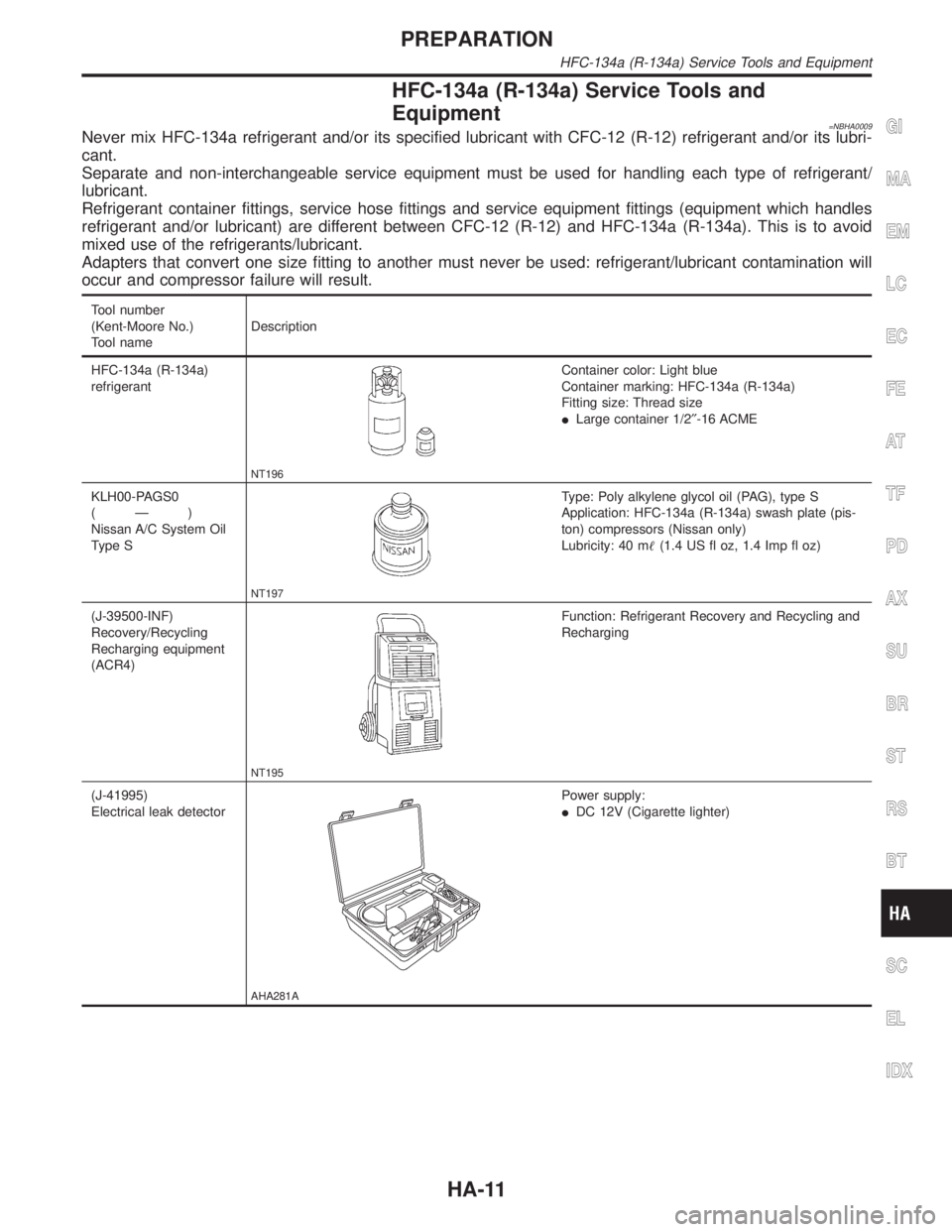
HFC-134a (R-134a) Service Tools and
Equipment
=NBHA0009Never mix HFC-134a refrigerant and/or its specified lubricant with CFC-12 (R-12) refrigerant and/or its lubri-
cant.
Separate and non-interchangeable service equipment must be used for handling each type of refrigerant/
lubricant.
Refrigerant container fittings, service hose fittings and service equipment fittings (equipment which handles
refrigerant and/or lubricant) are different between CFC-12 (R-12) and HFC-134a (R-134a). This is to avoid
mixed use of the refrigerants/lubricant.
Adapters that convert one size fitting to another must never be used: refrigerant/lubricant contamination will
occur and compressor failure will result.
Tool number
(Kent-Moore No.)
Tool nameDescription
HFC-134a (R-134a)
refrigerant
NT196
Container color: Light blue
Container marking: HFC-134a (R-134a)
Fitting size: Thread size
ILarge container 1/2²-16 ACME
KLH00-PAGS0
(Ð)
Nissan A/C System Oil
Type S
NT197
Type: Poly alkylene glycol oil (PAG), type S
Application: HFC-134a (R-134a) swash plate (pis-
ton) compressors (Nissan only)
Lubricity: 40 m(1.4 US fl oz, 1.4 Imp fl oz)
(J-39500-INF)
Recovery/Recycling
Recharging equipment
(ACR4)
NT195
Function: Refrigerant Recovery and Recycling and
Recharging
(J-41995)
Electrical leak detector
AHA281A
Power supply:
IDC 12V (Cigarette lighter)
GI
MA
EM
LC
EC
FE
AT
TF
PD
AX
SU
BR
ST
RS
BT
SC
EL
IDX
PREPARATION
HFC-134a (R-134a) Service Tools and Equipment
HA-11
Page 1811 of 2395
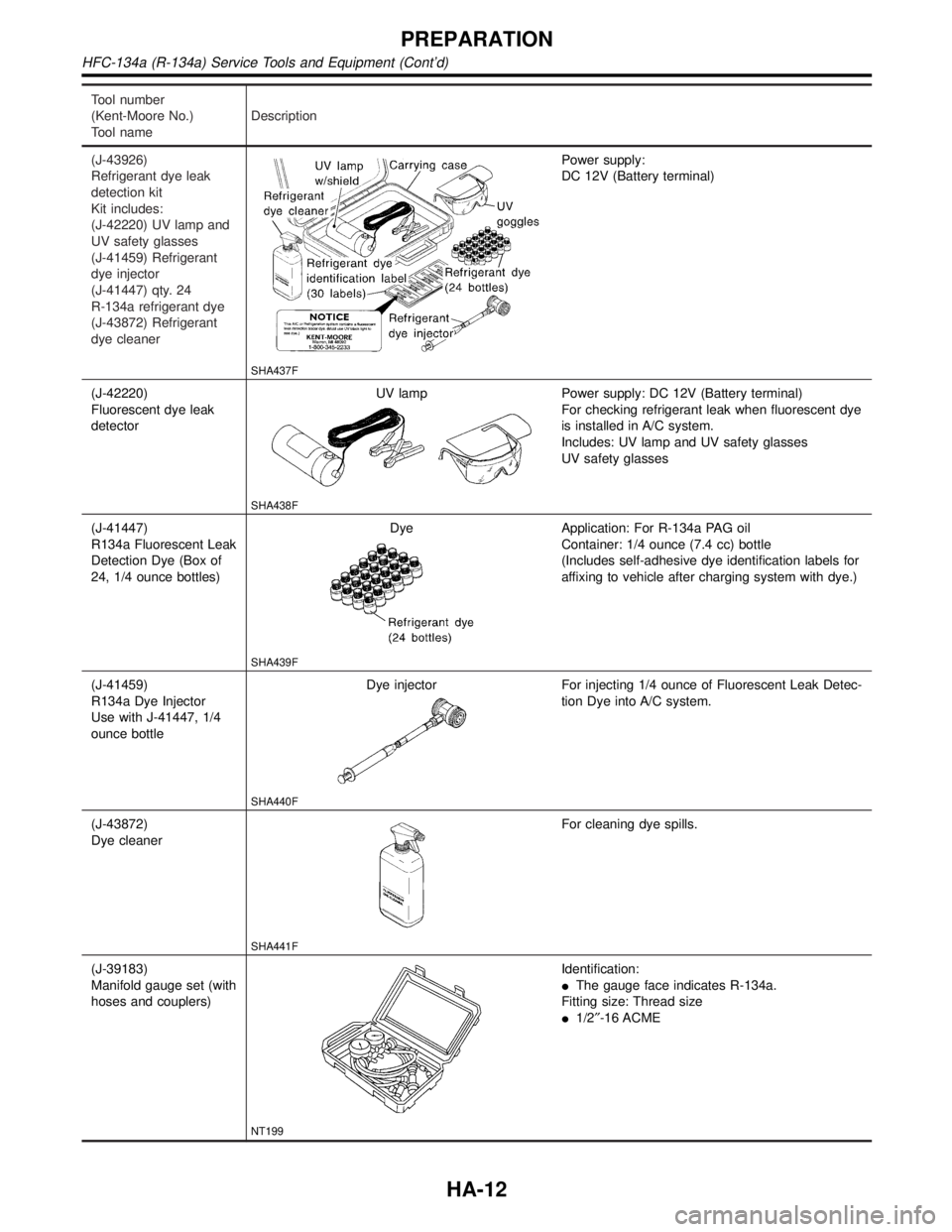
Tool number
(Kent-Moore No.)
Tool nameDescription
(J-43926)
Refrigerant dye leak
detection kit
Kit includes:
(J-42220) UV lamp and
UV safety glasses
(J-41459) Refrigerant
dye injector
(J-41447) qty. 24
R-134a refrigerant dye
(J-43872) Refrigerant
dye cleaner
SHA437F
Power supply:
DC 12V (Battery terminal)
(J-42220)
Fluorescent dye leak
detectorUV lamp
SHA438F
Power supply: DC 12V (Battery terminal)
For checking refrigerant leak when fluorescent dye
is installed in A/C system.
Includes: UV lamp and UV safety glasses
UV safety glasses
(J-41447)
R134a Fluorescent Leak
Detection Dye (Box of
24, 1/4 ounce bottles)Dye
SHA439F
Application: For R-134a PAG oil
Container: 1/4 ounce (7.4 cc) bottle
(Includes self-adhesive dye identification labels for
affixing to vehicle after charging system with dye.)
(J-41459)
R134a Dye Injector
Use with J-41447, 1/4
ounce bottleDye injector
SHA440F
For injecting 1/4 ounce of Fluorescent Leak Detec-
tion Dye into A/C system.
(J-43872)
Dye cleaner
SHA441F
For cleaning dye spills.
(J-39183)
Manifold gauge set (with
hoses and couplers)
NT199
Identification:
IThe gauge face indicates R-134a.
Fitting size: Thread size
I1/2²-16 ACME
PREPARATION
HFC-134a (R-134a) Service Tools and Equipment (Cont'd)
HA-12