width INFINITI QX50 2021 Owner's Manual
[x] Cancel search | Manufacturer: INFINITI, Model Year: 2021, Model line: QX50, Model: INFINITI QX50 2021Pages: 542, PDF Size: 3.51 MB
Page 202 of 542
•The system is designed as an aid to the
driver in showing large stationary ob-
jects directly behind the vehicle, to help
avoid damaging the vehicle.
• The distance guide line and the vehicle
width line should be used as a reference
only when the vehicle is on a level paved
surface. The distance viewed on the
monitor is for reference only and may be
different than the actual distance be-
tween the vehicle and displayed objects.
CAUTION
Do not scratch the camera lens when clean-
ing dirt or snow from the front of the
camera.
The RearView Monitor system automatically
shows a rear view of the vehicle in the upper
touch-screen display (upper display) when
the shift lever is shifted into the R (Reverse)
position. When activating the RearView
Monitor, the guide lines, the icons and the
messages may not be displayed immediately.
The radio can still be heard while the Rear-
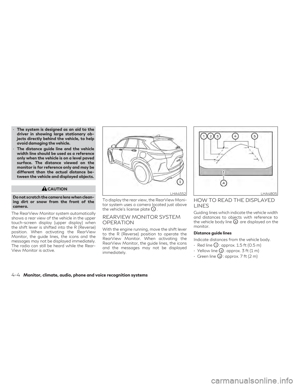
View Monitor is active. To display the rear view, the RearView Moni-
tor system uses a camera located just above
the vehicle’s license plate
O1.
REARVIEW MONITOR SYSTEM
OPERATION
With the engine running, move the shift lever
to the R (Reverse) position to operate the
RearView Monitor. When activating the
RearView Monitor, the guide lines, the icons
and the messages may not be displayed
immediately.
HOW TO READ THE DISPLAYED
LINES
Guiding lines which indicate the vehicle width
and distances to objects with reference to
the vehicle body line
OAare displayed on the
monitor.
Distance guide lines
Indicate distances from the vehicle body.
• Red line
O1: approx. 1.5 ft (0.5 m)
• Yellow line
O2: approx. 3 ft (1 m)
• Green line
O3: approx. 7 ft (2 m)
LHA4552LHA4805
4-4Monitor, climate, audio, phone and voice recognition systems
Page 203 of 542
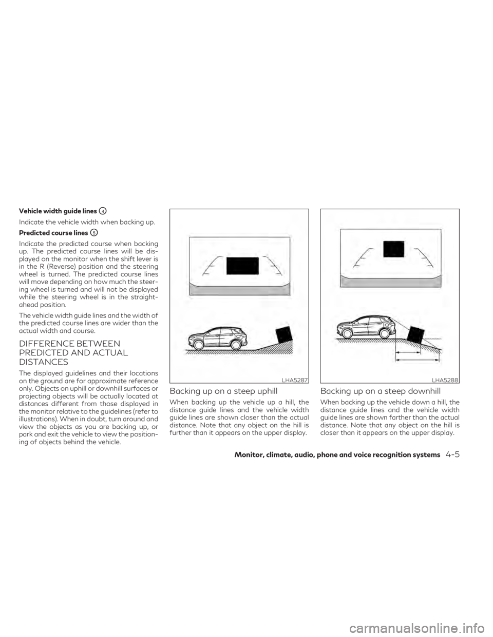
Vehicle width guide linesO4
Indicate the vehicle width when backing up.
Predicted course lines
O5
Indicate the predicted course when backing
up. The predicted course lines will be dis-
played on the monitor when the shift lever is
in the R (Reverse) position and the steering
wheel is turned. The predicted course lines
will move depending on how much the steer-
ing wheel is turned and will not be displayed
while the steering wheel is in the straight-
ahead position.
The vehicle width guide lines and the width of
the predicted course lines are wider than the
actual width and course.
DIFFERENCE BETWEEN
PREDICTED AND ACTUAL
DISTANCES
The displayed guidelines and their locations
on the ground are for approximate reference
only. Objects on uphill or downhill surfaces or
projecting objects will be actually located at
distances different from those displayed in
the monitor relative to the guidelines (refer to
illustrations). When in doubt, turn around and
view the objects as you are backing up, or
park and exit the vehicle to view the position-
ing of objects behind the vehicle.
Backing up on a steep uphill
When backing up the vehicle up a hill, the
distance guide lines and the vehicle width
guide lines are shown closer than the actual
distance. Note that any object on the hill is
further than it appears on the upper display.
Backing up on a steep downhill
When backing up the vehicle down a hill, the
distance guide lines and the vehicle width
guide lines are shown farther than the actual
distance. Note that any object on the hill is
closer than it appears on the upper display.
LHA5287LHA5288
Monitor, climate, audio, phone and voice recognition systems4-5
Page 205 of 542
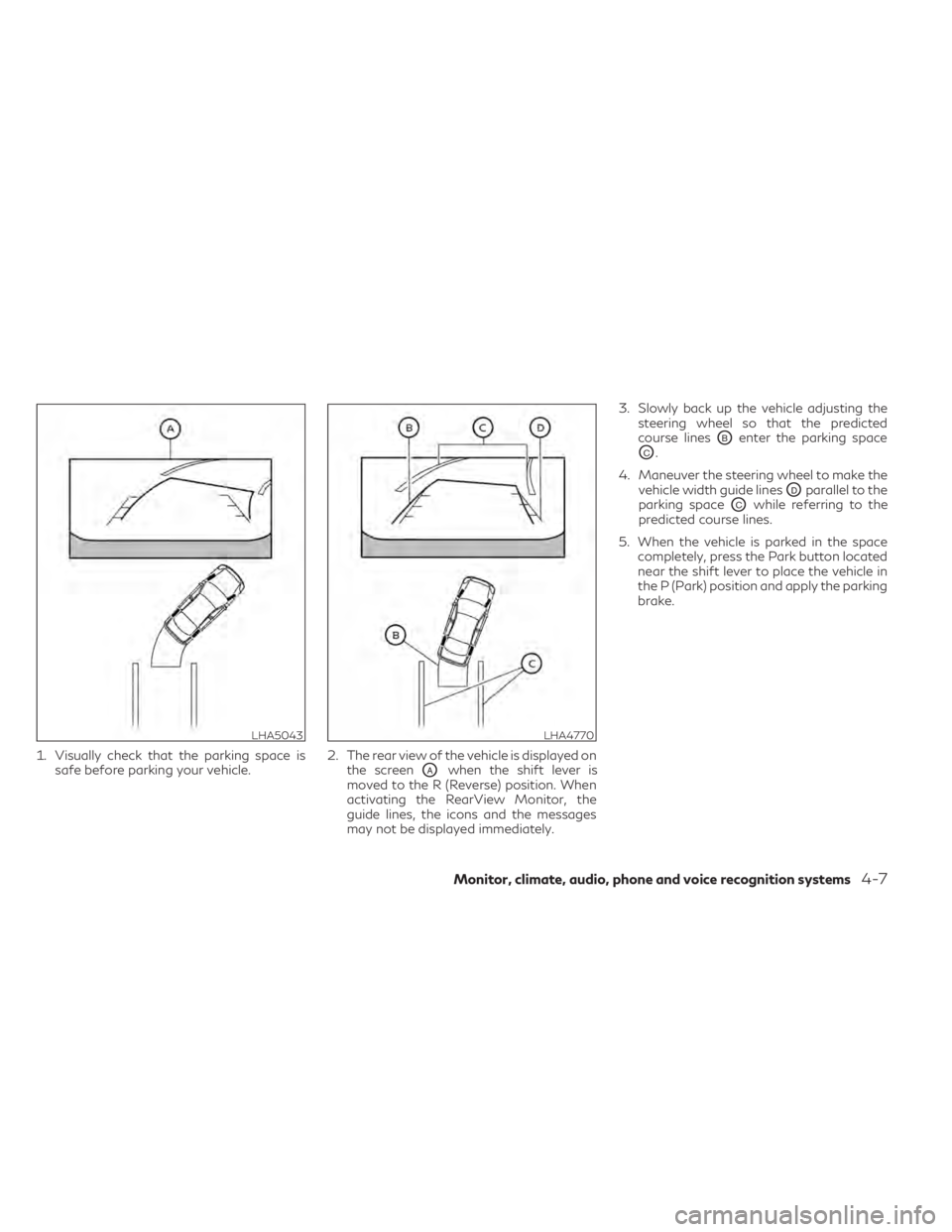
1. Visually check that the parking space issafe before parking your vehicle. 2. The rear view of the vehicle is displayed on
the screen
OAwhen the shift lever is
moved to the R (Reverse) position. When
activating the RearView Monitor, the
guide lines, the icons and the messages
may not be displayed immediately. 3. Slowly back up the vehicle adjusting the
steering wheel so that the predicted
course lines
OBenter the parking space
OC.
4. Maneuver the steering wheel to make the vehicle width guide lines
ODparallel to the
parking space
OCwhile referring to the
predicted course lines.
5. When the vehicle is parked in the space completely, press the Park button located
near the shift lever to place the vehicle in
the P (Park) position and apply the parking
brake.
LHA5043LHA4770
Monitor, climate, audio, phone and voice recognition systems4-7
Page 210 of 542
When the camera is first activated with the
bird’s-eye view in the display, a red icon will
flash on the upper display. This indicates that
the sonar system is activated. For additional
information on the front and rear sonar sys-
tem, see “Front and rear sonar system”
(P. 5-160).
Available views
WARNING
• The distance guide lines and the vehicle
width lines should be used as a reference
only when the vehicle is on a paved, level
surface. The apparent distance viewed
on the monitor may be different than the
actual distance between the vehicle and
displayed objects.
• Use the displayed lines and the bird’s-
eye view as a reference. The lines and the
bird’s-eye view are greatly affected by
the number of occupants, cargo, fuel
level, vehicle position, road condition
and road grade.
• If the tires are replaced with different
sized tires, the predicted course lines and
the bird's-eye view may be displayed
incorrectly. •
When driving the vehicle up a hill, objects
viewed in the monitor are further than
they appear. When driving the vehicle
down a hill, objects viewed in the monitor
are closer than they appear.
• Objects in the rear view will appear visu-
ally opposite compared to when viewed
in the monitor and outside mirrors.
• Use the mirrors or actually look to prop-
erly judge distances to other objects.
• On a snow-covered or slippery road,
there may be a difference between the
predicted course lines and the actual
course line.
• The vehicle width and predicted course
lines are wider than the actual width and
course.
• The displayed lines will appear slightly
off to the right, because the rearview
camera is not installed in the rear center
of the vehicle.
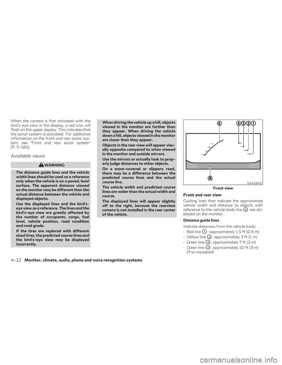
Front and rear view
Guiding lines that indicate the approximate
vehicle width and distance to objects with
reference to the vehicle body line
OAare dis-
played on the monitor.
Distance guide lines
Indicate distances from the vehicle body:
• Red line
O1: approximately 1.5 ft (0.5 m)
• Yellow line
O2: approximately 3 ft (1 m)
• Green line
O3: approximately 7 ft (2 m)
• Green line
O4: approximately 10 ft (3 m)
(if so equipped)
SAA1840
Front view
4-12Monitor, climate, audio, phone and voice recognition systems
Page 211 of 542
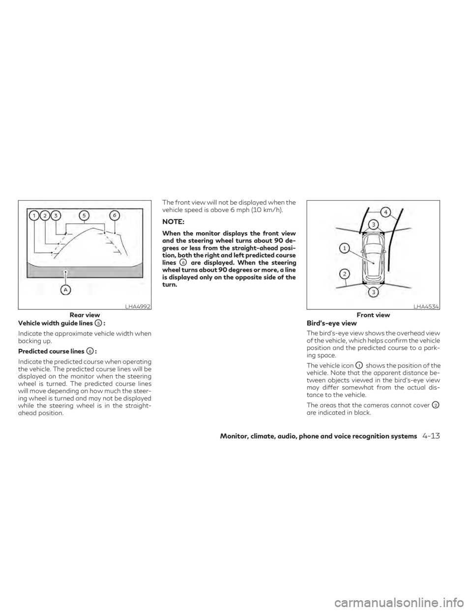
Vehicle width guide linesO5:
Indicate the approximate vehicle width when
backing up.
Predicted course lines
O6:
Indicate the predicted course when operating
the vehicle. The predicted course lines will be
displayed on the monitor when the steering
wheel is turned. The predicted course lines
will move depending on how much the steer-
ing wheel is turned and may not be displayed
while the steering wheel is in the straight-
ahead position. The front view will not be displayed when the
vehicle speed is above 6 mph (10 km/h).
NOTE:
When the monitor displays the front view
and the steering wheel turns about 90 de-
grees or less from the straight-ahead posi-
tion, both the right and left predicted course
lines
O6are displayed. When the steering
wheel turns about 90 degrees or more, a line
is displayed only on the opposite side of the
turn.
Bird’s-eye view
The bird's-eye view shows the overhead view
of the vehicle, which helps confirm the vehicle
position and the predicted course to a park-
ing space.
The vehicle icon
O1shows the position of the
vehicle. Note that the apparent distance be-
tween objects viewed in the bird's-eye view
may differ somewhat from the actual dis-
tance to the vehicle.
The areas that the cameras cannot cover
O2
are indicated in black.
LHA4992
Rear view
LHA4534
Front view
Monitor, climate, audio, phone and voice recognition systems4-13
Page 213 of 542
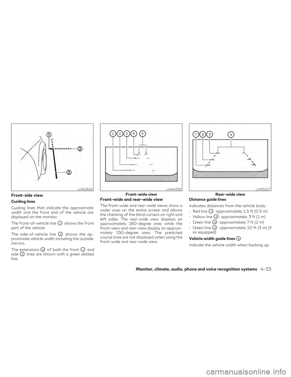
Front-side view
Guiding lines
Guiding lines that indicate the approximate
width and the front end of the vehicle are
displayed on the monitor.
The front-of-vehicle line
O1shows the front
part of the vehicle.
The side-of-vehicle line
O2shows the ap-
proximate vehicle width including the outside
mirrors.
The extensions
O3of both the frontO1and
side
O2lines are shown with a green dotted
line.
Front-wide and rear-wide view
The front-wide and rear-wide views show a
wider area on the entire screen and allows
the checking of the blind corners on right and
left sides. The rear-wide view displays an
approximately 180-degree area while the
front-view and rear-view display an approxi-
mately 150-degree area. The predicted
course lines are not displayed when using the
front-wide and rear-wide view. Distance guide lines
Indicates distances from the vehicle body:
• Red line
O1: approximately 1.5 ft (0.5 m)
• Yellow line
O2: approximately 3 ft (1 m)
• Green line
O3: approximately 7 ft (2 m)
• Green line
O4: approximately 10 ft (3 m) (if
so equipped)
Vehicle width guide lines
O5
Indicate the vehicle width when backing up.
LHA2652LHA4555
Front-wide view
LHA5217
Rear-wide view
Monitor, climate, audio, phone and voice recognition systems4-15
Page 214 of 542
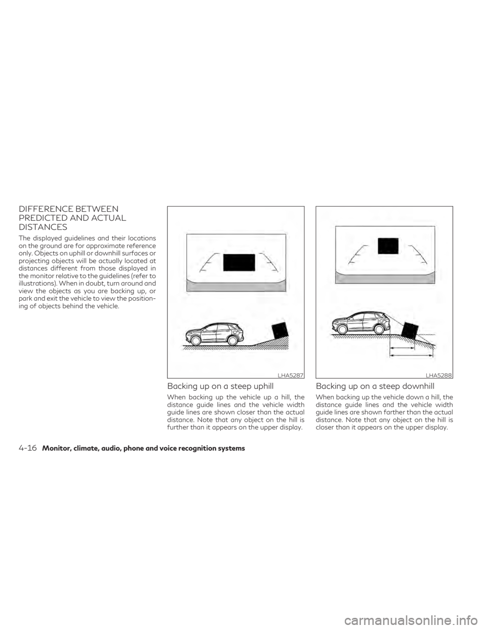
DIFFERENCE BETWEEN
PREDICTED AND ACTUAL
DISTANCES
The displayed guidelines and their locations
on the ground are for approximate reference
only. Objects on uphill or downhill surfaces or
projecting objects will be actually located at
distances different from those displayed in
the monitor relative to the guidelines (refer to
illustrations). When in doubt, turn around and
view the objects as you are backing up, or
park and exit the vehicle to view the position-
ing of objects behind the vehicle.
Backing up on a steep uphill
When backing up the vehicle up a hill, the
distance guide lines and the vehicle width
guide lines are shown closer than the actual
distance. Note that any object on the hill is
further than it appears on the upper display.
Backing up on a steep downhill
When backing up the vehicle down a hill, the
distance guide lines and the vehicle width
guide lines are shown farther than the actual
distance. Note that any object on the hill is
closer than it appears on the upper display.
LHA5287LHA5288
4-16Monitor, climate, audio, phone and voice recognition systems
Page 217 of 542
4. Maneuver the steering wheel to make thevehicle width guide lines
ODparallel to the
parking space
OCwhile referring to the
predicted course lines.
5. When the vehicle is parked in the space completely, press the Park button located
near the shift lever to place the vehicle in
the P (Park) position and apply the parking
brake.
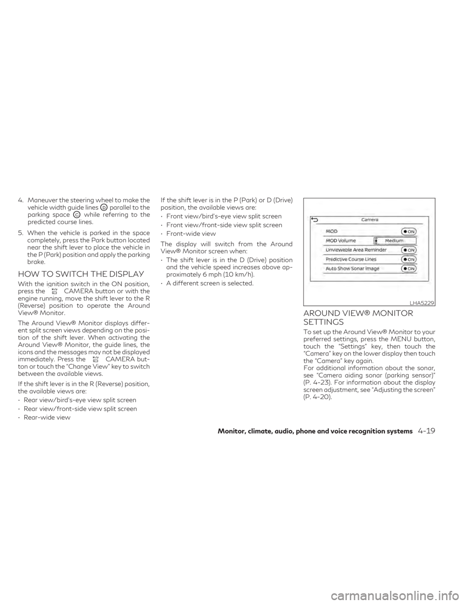
HOW TO SWITCH THE DISPLAY
With the ignition switch in the ON position,
press theCAMERA button or with the
engine running, move the shift lever to the R
(Reverse) position to operate the Around
View® Monitor.
The Around View® Monitor displays differ-
ent split screen views depending on the posi-
tion of the shift lever. When activating the
Around View® Monitor, the guide lines, the
icons and the messages may not be displayed
immediately. Press the
CAMERA but-
ton or touch the “Change View” key to switch
between the available views.
If the shift lever is in the R (Reverse) position,
the available views are:
• Rear view/bird’s-eye view split screen
• Rear view/front-side view split screen
• Rear-wide view If the shift lever is in the P (Park) or D (Drive)
position, the available views are:
• Front view/bird’s-eye view split screen
• Front view/front-side view split screen
• Front-wide view
The display will switch from the Around
View® Monitor screen when:
• The shift lever is in the D (Drive) position
and the vehicle speed increases above ap-
proximately 6 mph (10 km/h).
• A different screen is selected.
AROUND VIEW® MONITOR
SETTINGS
To set up the Around View® Monitor to your
preferred settings, press the MENU button,
touch the “Settings” key, then touch the
“Camera” key on the lower display then touch
the “Camera” key again.
For additional information about the sonar,
see “Camera aiding sonar (parking sensor)”
(P. 4-23). For information about the display
screen adjustment, see “Adjusting the screen”
(P. 4-20).
LHA5229
Monitor, climate, audio, phone and voice recognition systems4-19
Page 280 of 542
•Do not use the LDW system under the
following conditions as it may not func-
tion properly:
– During bad weather (rain, fog, snow,
etc.).
– When driving on slippery roads, such
as on ice or snow.
– When driving on winding or uneven
roads.
– When there is a lane closure due to
road repairs.
– When driving in a makeshift or tem-
porary lane.
– When driving on roads where the lane
width is too narrow.
– When driving without normal tire
conditions (for example, tire wear,
low tire pressure, installation of
spare tire, tire chains, nonstandard
wheels).
– When the vehicle is equipped with
non-original brake parts or suspen-
sion parts.
– When you are towing a trailer or
other vehicle. The system may not function properly under
the following conditions:
• On roads where there are multiple parallel
lane markers; lane markers that are faded
or not painted clearly; yellow painted lane
markers; non-standard lane markers; or
lane markers covered with water, dirt,
snow, etc.
• On roads where the discontinued lane markers are still detectable.
• On roads where there are sharp curves.
• On roads where there are sharply contrast- ing objects, such as shadows, snow, water,
wheel ruts, seams or lines remaining after
road repairs. (The LDW system could de-
tect these items as lane markers.)
• On roads where the traveling lane merges or separates.
• When the vehicle’s traveling direction does not align with the lane marker.
• When traveling close to the vehicle in front of you, which obstructs the lane camera
unit detection range.
• When rain, snow, dirt or an object adheres to the windshield in front of the lane cam-
era unit.
• When the headlights are not bright due to dirt on the lens or if the aiming is not ad-
justed properly. • When strong light enters the lane camera
unit. (For example, the light directly shines
on the front of the vehicle at sunrise or
sunset.)
• When a sudden change in brightness oc- curs. (For example, when the vehicle enters
or exits a tunnel or under a bridge.)
SYSTEM TEMPORARILY
UNAVAILABLE
If the vehicle is parked in direct sunlight under
high temperature conditions (over approxi-
mately 104°F [40°C]) and then started, the
LDW system may be deactivated automati-
cally and the following message will appear in
the vehicle information display: “Not avail-
able: High Camera Temp.”
When the interior temperature is reduced, the
LDW system will resume operating
automatically.
The LDW system is not designed to warn
under the following conditions:
• When you operate the lane change signaland change traveling lanes in the direction
of the signal. (The LDW system will become
operable again approximately 2 seconds
after the lane change signal is turned off.)
• When the vehicle speed lowers to less than approximately 37 mph (60 km/h).
5-38Starting and driving
Page 285 of 542
•The LDP system may activate if you
change lanes without first activating
your turn signal or, for example, if a con-
struction zone directs traffic to cross an
existing lane marker. If this occurs you
may need to apply corrective steering to
complete your lane change.
• Because the LDP may not activate under
the road, weather, and lane marker con-
ditions described in this section, it may
not activate every time your vehicle be-
gins to leave its lane and you will need to
apply corrective steering.
• The LDP system will not operate at
speeds below approximately 37 mph (60
km/h) or if it cannot detect lane markers.
• Do not use the LDP system under the
following conditions as it may not func-
tion properly:
– During bad weather (rain, fog, snow,
etc.).
– When driving on slippery roads, such
as on ice or snow.
– When driving on winding or uneven
roads.
– When there is a lane closure due to
road repairs.
– When driving in a makeshift or tem-
porary lane. –
When driving on roads where the lane
width is too narrow.
– When driving without normal tire
conditions (for example, tire wear,
low tire pressure, installation of
spare tire, tire chains, non-standard
wheels).
– When the vehicle is equipped with
nonoriginal brake parts or suspen-
sion parts.
– When you are towing a trailer or
other vehicle.
The system may not function properly un-
der the following conditions:
• On roads where there are multiple paral-
lel lane markers; lane markers that are
faded or not painted clearly; yellow
painted lane markers; non-standard lane
markers; or lane markers covered with
water, dirt, snow, etc.
• On roads where discontinued lane mark-
ers are still detectable.
• On roads where there are sharp curves.
• On roads where there are sharply con-
trasting objects, such as shadows, snow,
water, wheel ruts, seams or lines remain-
ing after road repairs. (The LDP system
could detect these items as lane markers.)
• On roads where the traveling lane
merges or separates.
• When the vehicle’s traveling direction
does not align with the lane marker.
• When traveling close to the vehicle in
front of you, which obstructs the lane
camera unit detection range.
• When rain, snow or dirt adheres to the
windshield in front of the lane camera
unit.
• When the headlights are not bright due
to dirt on the lens or if the aiming is not
adjusted properly.
• When strong light enters the lane cam-
era unit. (For example, the light directly
shines on the front of the vehicle at sun-
rise or sunset.)
• When a sudden change in brightness oc-
curs. (For example, when the vehicle en-
ters or exits a tunnel or under a bridge.)
While the LDP system is operating, you may
hear a sound of brake operation. This is nor-
mal and indicates that the LDP system is
operating properly.
Starting and driving5-43