sensor INFINITI QX50 2022 Owner's Guide
[x] Cancel search | Manufacturer: INFINITI, Model Year: 2022, Model line: QX50, Model: INFINITI QX50 2022Pages: 540, PDF Size: 6.58 MB
Page 196 of 540

Type A (if so equipped)
The indicator lightO2will illuminate when the
automatic anti-glare sensor feature is
operating.
With the ignition switch in the ON position,
press the
button as described:
• To turn off the anti-glare feature, press the
button. The indicator light will turn
off.
• To turn on the anti-glare feature, press the
button again. The indicator light will
turn on.
NOTE:
Do not hang any objects over the sensorsO1
or apply glass cleaner to the sensors. Doing
so will reduce the sensitivity of the sensors,
resulting in improper operation.
Type B (if so equipped)
The indicator lightO2will illuminate when the
automatic anti-glare feature is operating.
• To turn off the automatic anti-glare fea- ture, press the O button. The indicator
light will turn off.
• To turn on the automatic anti-glare fea- ture, press the | button again. The indi-
cator light will turn on.
For additional information on HomeLink®
Universal Transceiver operation, see
“HomeLink® Universal Transceiver” (P. 2-73).
LPD3113LPD0469
3-34Pre-driving checks and adjustments
Page 197 of 540
NOTE:
Do not hang any objects over the sensorsO1
or apply glass cleaner to the sensors. Doing
so will reduce the sensitivity of the sensors,
resulting in improper operation.
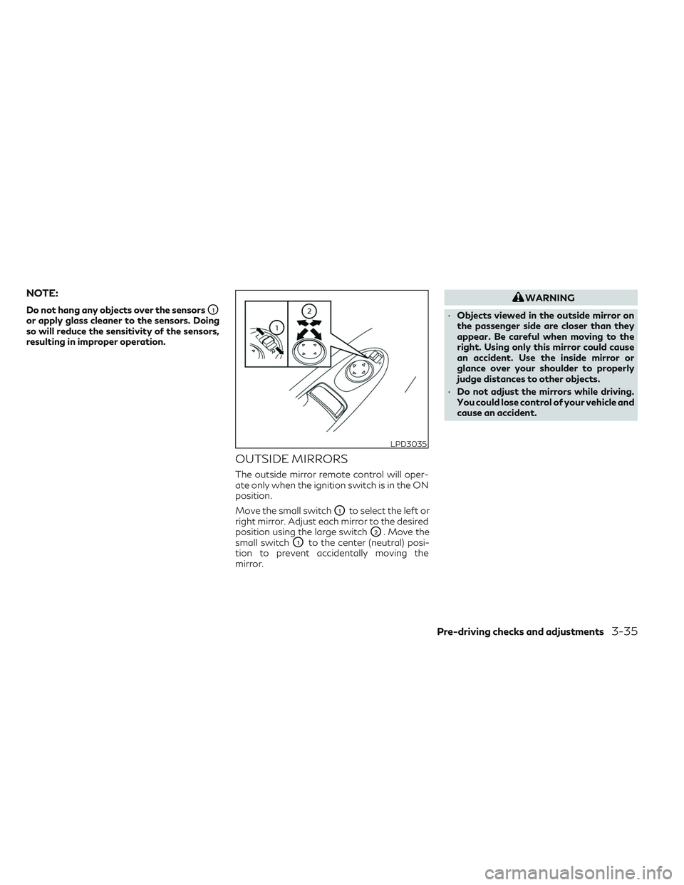
OUTSIDE MIRRORS
The outside mirror remote control will oper-
ate only when the ignition switch is in the ON
position.
Move the small switch
O1to select the left or
right mirror. Adjust each mirror to the desired
position using the large switch
O2. Move the
small switch
O1to the center (neutral) posi-
tion to prevent accidentally moving the
mirror.
WARNING
• Objects viewed in the outside mirror on
the passenger side are closer than they
appear. Be careful when moving to the
right. Using only this mirror could cause
an accident. Use the inside mirror or
glance over your shoulder to properly
judge distances to other objects.
• Do not adjust the mirrors while driving.
You could lose control of your vehicle and
cause an accident.
LPD3035
Pre-driving checks and adjustments3-35
Page 203 of 540
4 Monitor, climate, audio, phone and voice
recognition systems
INFINITI InTouchTMOwner’s Manual.............4-2
RearView Monitor (if so equipped) ................4-3
RearView Monitor system operation ...........4-4
How to read the displayed lines ................4-4
Difference between predicted and actual
distances .....................................4-5
How to park with predicted course lines .......4-7
Adjusting the screen ......................... 4-8
How to turn on and off predicted course
lines ..........................................4-9
RearView Monitor system limitations ..........4-9
System maintenance ........................ 4-10
Around View® Monitor (if so equipped) ..........4-11
Around View® Monitor system operation ....4-12
Difference between predicted and actual
distances .................................... 4-17
How to park with predicted course lines .....4-18
How to switch the display ...................4-20
Around View® Monitor settings .............4-20
Adjusting the screen ........................ 4-21
Around View® Monitor system
limitations .................................. 4-22
System maintenance ........................ 4-24
Camera aiding sonar (parking sensor)
(if so equipped) ................................ 4-24Sonar system operation
.....................4-25
Turning on and off the sonar function ........4-26
Sonar system limitations ....................4-27
System maintenance ........................ 4-28
Moving Object Detection (MOD)
(if so equipped) ................................ 4-29
MOD system operation .....................4-30
Turning MOD on and off ....................4-32
MOD system limitations .....................4-32
System maintenance ........................ 4-33
Vents .......................................... 4-34
Heater and air conditioner (automatic) ..........4-35
Automatic operation ........................ 4-36
Manual operation ........................... 4-37
Operating tips .............................. 4-38
CLIMATE setting screen ....................4-39
Rear climate control (if so equipped) .........4-41
Heater and air conditioner settings
(if
so equipped) ................................ 4-42
Servicing air conditioner ........................ 4-43
Antenna ....................................... 4-43
Car phone or CB radio ......................... 4-44
iPod®/iPhone® ................................ 4-44
Page 222 of 540
4. Maneuver the steering wheel to make thevehicle width guide lines
ODparallel to the
parking space
OCwhile referring to the
predicted course lines.
5. When the vehicle is parked in the space completely, press the P (Park) button lo-
cated near the shift lever to place the
vehicle in the P (Park) position and apply
the parking brake.
HOW TO SWITCH THE DISPLAY
With the ignition switch in the ON position,
press theCAMERA button or with the
engine running, move the shift lever to the R
(Reverse) position to operate the Around
View® Monitor.
The Around View® Monitor displays differ-
ent split screen views depending on the posi-
tion of the shift lever. When activating the
Around View® Monitor, the guide lines, the
icons and the messages may not be displayed
immediately. Press the
CAMERA but-
ton or touch the “Change View” key to switch
between the available views. If the shift lever is in the R (Reverse) position,
the available views are:
• Rear view/bird’s-eye view split screen
• Rear view/front-side view split screen
• Rear-wide view
If the shift position is in the P (Park) or D
(Drive) position, the available views are:
• Front view/bird’s-eye view split screen
• Front view/front-side view split screen
• Front-wide view
The display will switch from the Around
View® Monitor screen when:
• The shift lever is in the D (Drive) position
and the vehicle speed increases above ap-
proximately 6 mph (10 km/h).
• A different screen is selected.
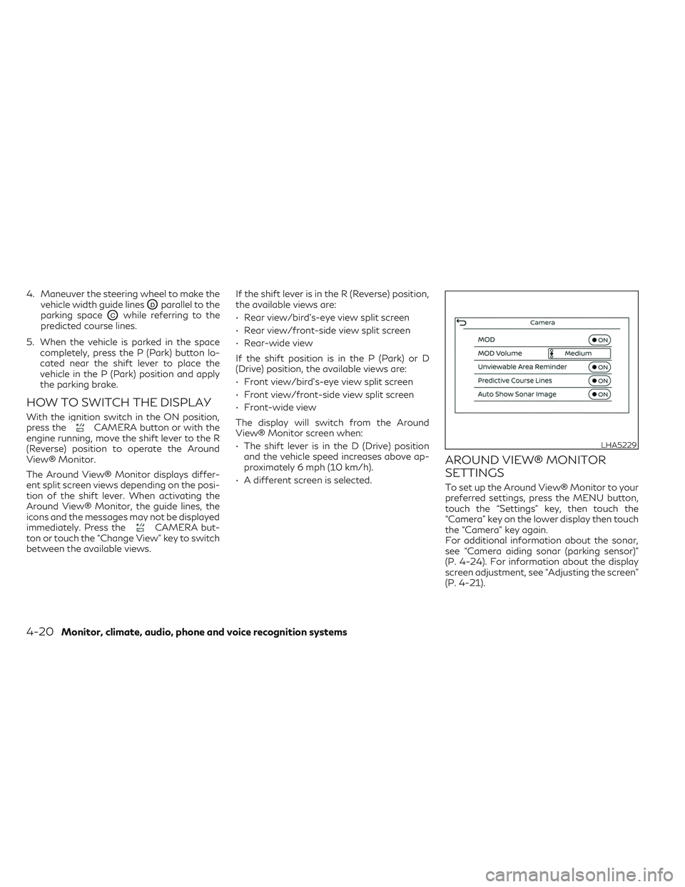
AROUND VIEW® MONITOR
SETTINGS
To set up the Around View® Monitor to your
preferred settings, press the MENU button,
touch the “Settings” key, then touch the
“Camera” key on the lower display then touch
the “Camera” key again.
For additional information about the sonar,
see “Camera aiding sonar (parking sensor)”
(P. 4-24). For information about the display
screen adjustment, see “Adjusting the screen”
(P. 4-21).
LHA5229
4-20Monitor, climate, audio, phone and voice recognition systems
Page 226 of 540
SYSTEM MAINTENANCE
CAUTION
• Do not use alcohol, benzine or thinner to
clean the camera. This will cause
discoloration.
• Do not damage the cameras as the moni-
tor screen may be adversely affected.
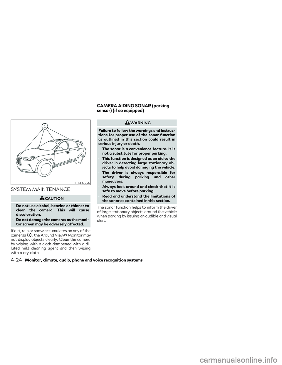
If dirt, rain or snow accumulates on any of the
cameras
O1, the Around View® Monitor may
not display objects clearly. Clean the camera
by wiping with a cloth dampened with a di-
luted mild cleaning agent and then wiping
with a dry cloth.
WARNING
Failure to follow the warnings and instruc-
tions for proper use of the sonar function
as outlined in this section could result in
serious injury or death.
• The sonar is a convenience feature. It is
not a substitute for proper parking.
• This function is designed as an aid to the
driver in detecting large stationary ob-
jects to help avoid damaging the vehicle.
• The driver is always responsible for
safety during parking and other
maneuvers.
• Always look around and check that it is
safe to move before parking.
• Read and understand the limitations of
the sonar as contained in this section.
The sonar function helps to inform the driver
of large stationary objects around the vehicle
when parking by issuing an audible and visual
alert.
LHA4554
CAMERA AIDING SONAR (parking
sensor) (if so equipped)
4-24Monitor, climate, audio, phone and voice recognition systems
Page 229 of 540
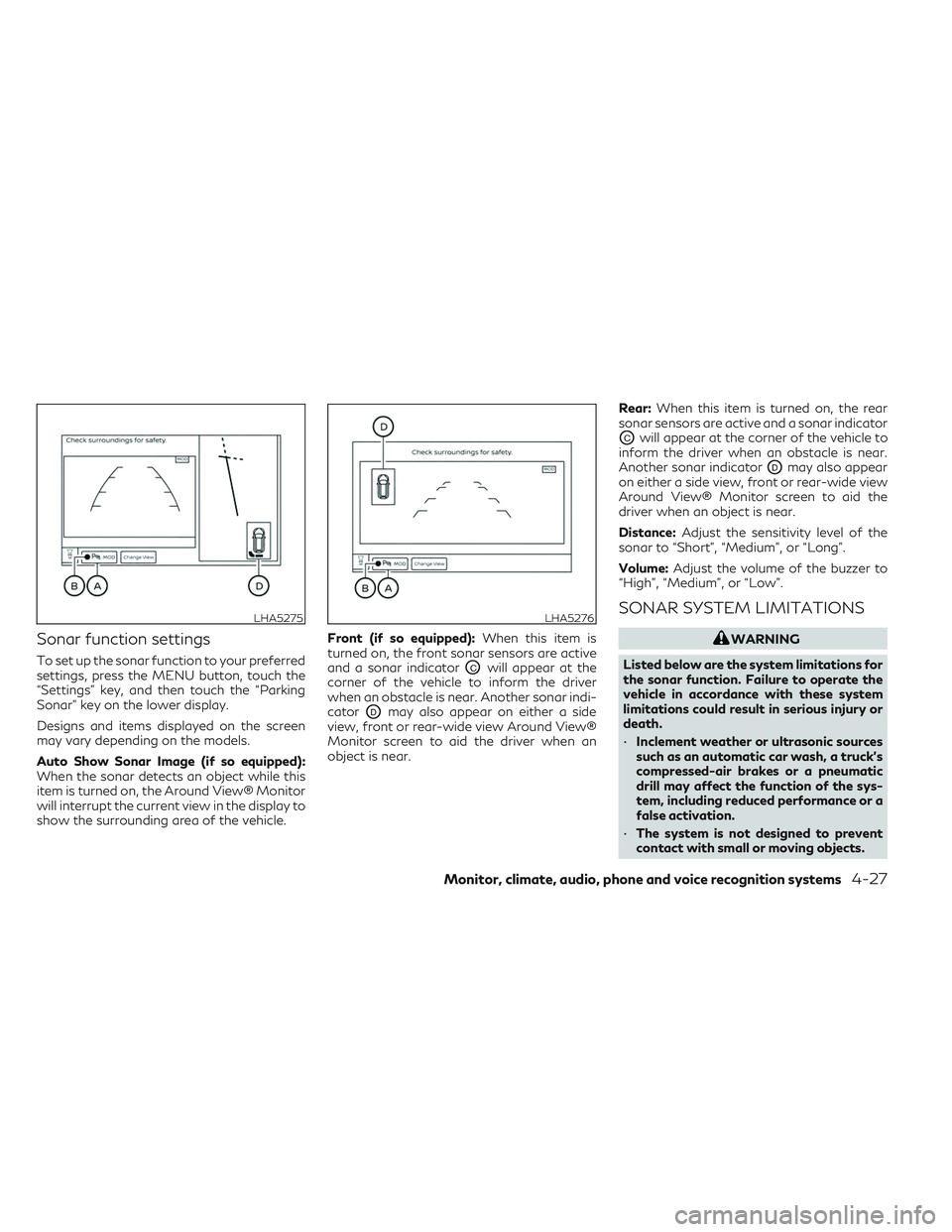
Sonar function settings
To set up the sonar function to your preferred
settings, press the MENU button, touch the
“Settings” key, and then touch the “Parking
Sonar” key on the lower display.
Designs and items displayed on the screen
may vary depending on the models.
Auto Show Sonar Image (if so equipped):
When the sonar detects an object while this
item is turned on, the Around View® Monitor
will interrupt the current view in the display to
show the surrounding area of the vehicle.Front (if so equipped):
When this item is
turned on, the front sonar sensors are active
and a sonar indicatorOCwill appear at the
corner of the vehicle to inform the driver
when an obstacle is near. Another sonar indi-
cator
ODmay also appear on either a side
view, front or rear-wide view Around View®
Monitor screen to aid the driver when an
object is near. Rear:
When this item is turned on, the rear
sonar sensors are active and a sonar indicator
OCwill appear at the corner of the vehicle to
inform the driver when an obstacle is near.
Another sonar indicator
ODmay also appear
on either a side view, front or rear-wide view
Around View® Monitor screen to aid the
driver when an object is near.
Distance: Adjust the sensitivity level of the
sonar to “Short”, “Medium”, or “Long”.
Volume: Adjust the volume of the buzzer to
“High”, “Medium”, or “Low”.
SONAR SYSTEM LIMITATIONS
WARNING
Listed below are the system limitations for
the sonar function. Failure to operate the
vehicle in accordance with these system
limitations could result in serious injury or
death.
• Inclement weather or ultrasonic sources
such as an automatic car wash, a truck’s
compressed-air brakes or a pneumatic
drill may affect the function of the sys-
tem, including reduced performance or a
false activation.
• The system is not designed to prevent
contact with small or moving objects.
LHA5275LHA5276
Monitor, climate, audio, phone and voice recognition systems4-27
Page 230 of 540
•The system will not detect small objects
below the bumper, and may not detect
objects close to the bumper or on the
ground.
• The system may not detect the following
objects:
– Fluffy objects such as snow, cloth,
cotton, grass or wool.
– Thin objects such as rope, wire or
chain.
– Wedge-shaped objects.
• If your vehicle sustains damage to the
bumper fascia, leaving it misaligned or
bent, the sensing zone may be altered
causing inaccurate measurement of ob-
jects or false alarms.
CAUTION
Excessive noise (such as audio system vol-
ume or an open vehicle window) will inter-
fere with the tone and it may not be heard.
System temporarily unavailable
When the amber markers are displayed at the
corners of the vehicle icon and the function
cannot be activated from the Camera setting
menu (the setting items are grayed out), the
sonar system may be malfunctioning.
SYSTEM MAINTENANCE
CAUTION
Keep the surface of the sonar sensors (lo-
cated on the front and rear bumper fascia)
free from accumulations of snow, ice and
dirt. Do not scratch the surface of the sonar
sensors when cleaning. If the sensors are
covered, the accuracy of the sonar function
will be diminished.
4-28Monitor, climate, audio, phone and voice recognition systems
Page 240 of 540
Rear window and outside mirror (if
so equipped) defroster switch
For additional information, see “Rear window
defroster, outside mirror defroster, and wiper
deicer switch” (P. 2-35).
Heated seat switches (if so
equipped)
For additional information, see “Heated
seats” (P. 2-45).
Climate controlled seat switches (if
so equipped)
For additional information, see “Climate con-
trolled seat switches” (P. 2-44).
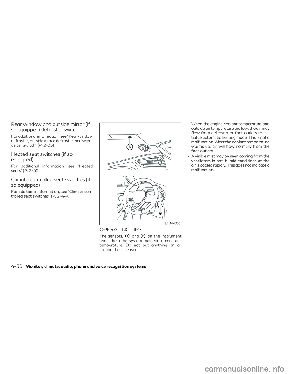
OPERATING TIPS
The sensors,OAandOBon the instrument
panel, help the system maintain a constant
temperature. Do not put anything on or
around these sensors. • When the engine coolant temperature and
outside air temperature are low, the air may
flow from defroster or foot outlets to ini-
tialize automatic heating mode. This is not a
malfunction. After the coolant temperature
warms up, air will flow normally from the
foot outlets
• A visible mist may be seen coming from the ventilators in hot, humid conditions as the
air is cooled rapidly. This does not indicate a
malfunction.
LHA4686
4-38Monitor, climate, audio, phone and voice recognition systems
Page 243 of 540

Ion control:
The Automatic Climate Control System unit
generates highly concentrated Plasmaclus-
ter® ions into the air blown from the ventila-
tors to reduce odor absorbed into the interior
trim and to suppress airborne bacteria. The
high-density Plasmacluster® ions also have a
proven skin moisture preserving effect.
The Plasmacluster® icon on the CLIMATE
screen indicates the status of the Plasma-
cluster® ion emission from the system and
changes with the amount of the air flow.
Automatic air recirculation control with the
exhaust gas/outside odor detection sensor:
The Automatic Climate Control System
comes with an exhaust gas detection/
outside odor sensor. When the automatic air
circulation control is activated, the sensor de-
tects odors outside the vehicle such as pulp or
chemicals, and exhaust such as gasoline or
diesel. When such odors or gases are de-
tected the display and the system automati-
cally change from fresh air mode to the recir-
culation mode.
When the automatic air recirculation is on, for
the first 5 minutes, the air recirculation mode
is selected to prevent dust, dirt, and pollen
from entering the vehicle and to clean the air
inside of the vehicle.After 5 minutes, the sensor detects exhaust
gas and automatically alternates between
the air recirculation mode and the fresh air
mode.
The automatic air recirculation mode can be
activated under the following conditions.
• The air flow control is not in the front de-
froster mode (the indicator light on the
front defroster button is turned off).
• The outside temperature is about 32°F (0°C) or more.
REAR CLIMATE CONTROL (if so
equipped)
1. Rear temperature display
2.Rear temperature control increase
button
3.
Rear temperature control decrease
button
You can adjust the climate control system for
rear seat passengers using the buttons on the
back of the console.
Press the
to increase the rear
temperature.
LHA4582
Rear temperature switch (if so equipped)
Monitor, climate, audio, phone and voice recognition systems4-41
Page 255 of 540
•When using g a wheel without the TPMS
such as the spare tire, when a spare tire is
mounted or a wheel is replaced, tire pres-
sure will not be indicated, the TPMS will
not function and the low tire pressure
warning light will flash for approxi-
mately 1 minute. The light will remain on
after 1 minute. Have your tires replaced
and/or TPMS system reset as soon as
possible. It is recommended that you
visit an INFINITI retailer for this service.
• Replacing tires with those not originally
specified by INFINITI could affect the
proper operation of the TPMS.
• Do not inject any tire liquid or aerosol tire
sealant into the tires, as this may cause a
malfunction of the tire pressure sensors.
CAUTION
• The TPMS may not function properly
when the wheels are equipped with tire
chains or the wheels are buried in snow.
• Do not place metalized film or any metal
parts (antenna, etc.) on the windows.
This may cause poor reception of the sig-
nals from the tire pressure sensors, and
the TPMS will not function properly. Some devices and transmitters may tempo-
rarily interfere with the operation of the
TPMS and cause the low tire pressure
warning light to illuminate.
Some examples are:
• Facilities or electric devices using similar
radio frequencies are near the vehicle.
• If a transmitter set to similar frequencies is being used in or near the vehicle.
• If a computer (or similar equipment) or a DC/AC converter is being used in or near
the vehicle.
The low tire pressure warning light may illu-
minate in the following cases:
• If the vehicle is equipped with a wheel and tire without TPMS.
• If the TPMS has been replaced and the ID has not been registered.
• If the wheel is not originally specified by INFINITI. FCC Notice:
For USA:
This device complies with Part 15 of the FCC
Rules. Operation is subject to the following
two conditions: (1) This device may not
cause harmful interference, and (2) this de-
vice must accept any interference received,
including interference that may cause unde-
sired operation.
Note: Changes or modifications not ex-
pressly approved by the party responsible
for compliance could void the user’s author-
ity to operate the equipment.
For Canada:
This device contains licence-exempt
transmitter(s)/receiver(s) that comply with
Innovation, Science and Economic Develop-
ment Canada’s licence-exempt RSS(s). Op-
eration is subject to the following two con-
ditions: (1) This device may not cause
interference. (2) This device must accept any
interference, including interference that
may cause undesired operation of the
device.
Starting and driving5-7