PG-2Revision: August 20072004 QX56 SRS COMPONENT TYPE) ................................. 70
ELECTRICAL UNITS ................................................ 71
Terminal Arrangement ............................................ 71
STANDARDIZED RELAY .......................................... 72
Description .............................................................. 72
NORMAL OPEN, NORMAL CLOSED AND
MIXED TYPE RELAYS ........................................ 72
TYPE OF STANDARDIZED RELAYS .................. 72SUPER MULTIPLE JUNCTION (SMJ) ......................74
Terminal Arrangement .............................................74
FUSE BLOCK-JUNCTION BOX(J/B) .......................76
Terminal Arrangement .............................................76
FUSE AND FUSIBLE LINK BOX ..............................77
Terminal Arrangement .............................................77
FUSE AND RELAY BOX ...........................................78
Terminal Arrangement .............................................78
PRECAUTIONS
PG-3
C
D
E
F
G
H
I
J
L
MA
B
PG
Revision: August 20072004 QX56
PRECAUTIONS PFP:00011
Precautions for Supplemental Restraint System (SRS) “AIR BAG” and “SEAT
BELT PRE-TENSIONER”
EKS007NJ
The Supplemental Restraint System such as “AIR BAG” and “SEAT BELT PRE-TENSIONER”, used along
with a front seat belt, helps to reduce the risk or severity of injury to the driver and front passenger for certain
types of collision. This system includes seat belt switch inputs and dual stage front air bag modules. The SRS
system uses the seat belt switches to determine the front air bag deployment, and may only deploy one front
air bag, depending on the severity of a collision and whether the front occupants are belted or unbelted.
Information necessary to service the system safely is included in the SRS and SB section of this Service Man-
ual.
WA RN ING:
�To avoid rendering the SRS inoperative, which could increase the risk of personal injury or death
in the event of a collision which would result in air bag inflation, all maintenance must be per-
formed by an authorized NISSAN/INFINITI dealer.
�Improper maintenance, including incorrect removal and installation of the SRS, can lead to per-
sonal injury caused by unintentional activation of the system. For removal of Spiral Cable and Air
Bag Module, see the SRS section.
�Do not use electrical test equipment on any circuit related to the SRS unless instructed to in this
Service Manual. SRS wiring harnesses can be identified by yellow and/or orange harnesses or
harness connectors.
Wiring Diagrams and Trouble DiagnosisEKS007NK
When you read wiring diagrams, refer to the following:
�Refer to GI-15, "How to Read Wiring Diagrams" in GI section.
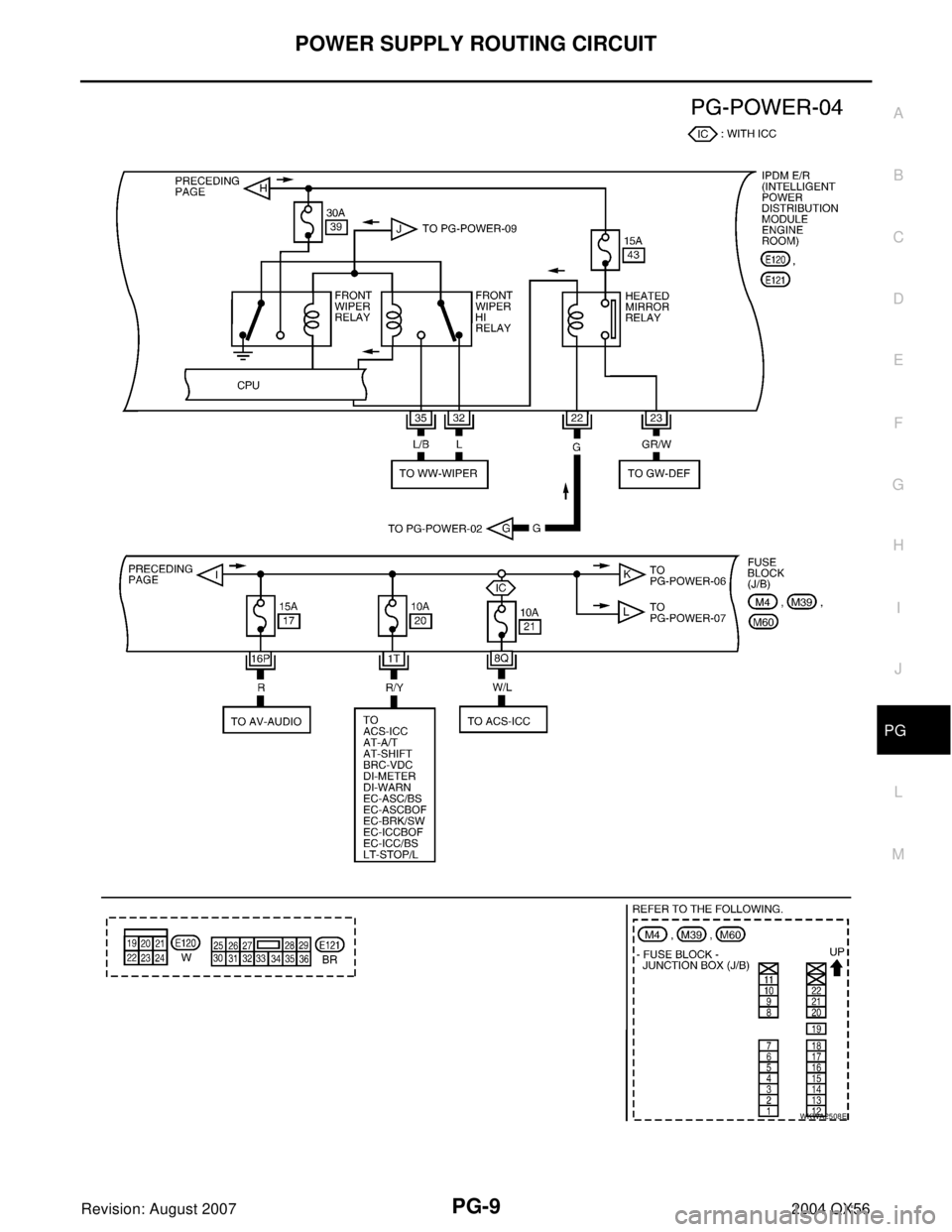
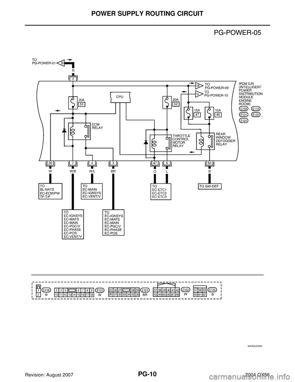
�Refer to PG-4, "POWER SUPPLY ROUTING CIRCUIT" for power distribution.
When you perform trouble diagnosis, refer to the following:
�Refer to GI-11, "HOW TO FOLLOW TEST GROUPS IN TROUBLE DIAGNOSES" in GI section.
�Refer to GI-27, "How to Perform Efficient Diagnosis for an Electrical Incident" in GI section.
PG-4
POWER SUPPLY ROUTING CIRCUIT
Revision: August 20072004 QX56
POWER SUPPLY ROUTING CIRCUITPFP:24110
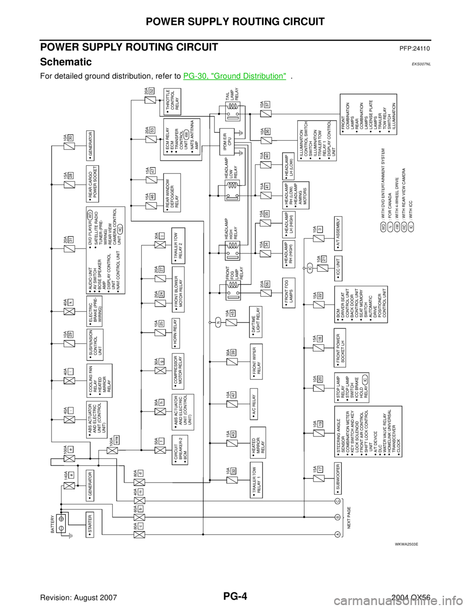
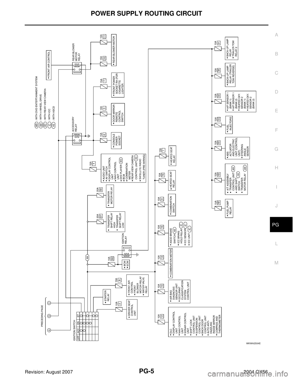
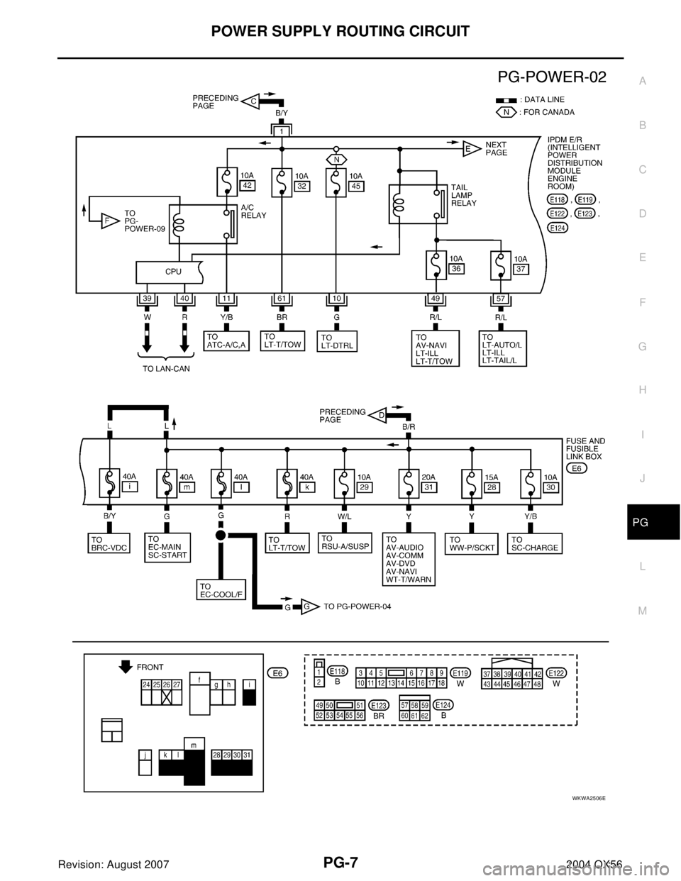
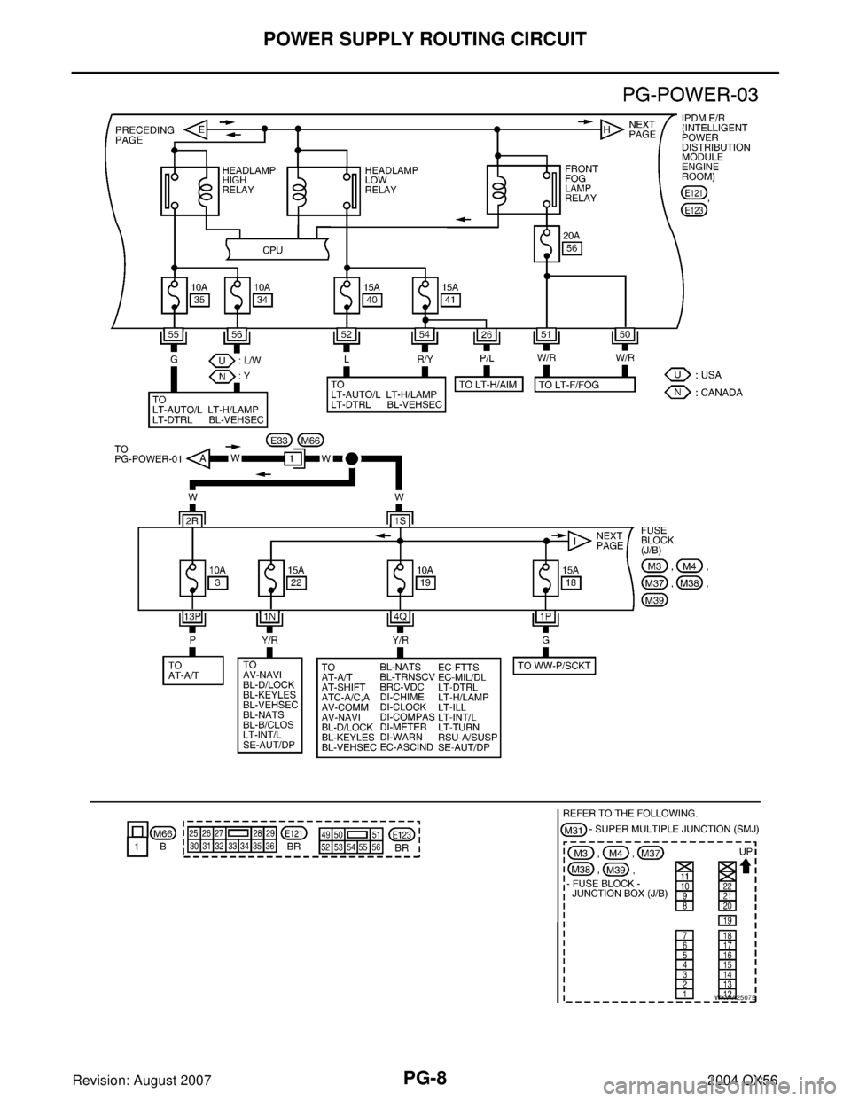
SchematicEKS007NL
For detailed ground distribution, refer to PG-30, "Ground Distribution" .
WKWA2503E


