diagram INFINITI QX56 2006 Factory Workshop Manual
[x] Cancel search | Manufacturer: INFINITI, Model Year: 2006, Model line: QX56, Model: INFINITI QX56 2006Pages: 3383, PDF Size: 51.76 MB
Page 1123 of 3383

DI-2Revision: November 20092006 QX56
Wiring Diagram — CHIME — ..............................
... 46
Terminals and Reference Value for BCM ............. ... 48
Terminals and Reference Value for Combination
Meter ................................................................... ... 49
How to Proceed With Trouble Diagnosis ............. ... 49
Preliminary Check ............................................... ... 50
INSPECTION FOR POWER SUPPLY AND
GROUND CIRCUIT .......................................... ... 50
CONSULT-II Function (BCM) ............................... ... 51
CONSULT-II BASIC OPERATION PROCEDURE ... 51
DATA MONITOR ............................................... ... 52
ACTIVE TEST .................................................. ... 52
SELF-DIAGNOSTIC RESULTS ........................ ... 53
All Warning Chimes Do Not Operate ................... ... 53
Key Warning Chime and Light Warning Chime Do
Not Operate (Seat Belt Warning Chime Does Oper-
ate) ...................................................................... ... 54
Key Warning Chime Does Not Operate ............... ... 55
Light Warning Chime Does Not Operate ............. ... 57
Seat Belt Warning Chime Does Not Operate ...... ... 58
REAR SONAR SYSTEM ........................................ ... 60
Component Parts and Harness Connector Location ... 60
System Description .............................................. ... 61
FUNCTION ....................................................... ... 61
REAR SONAR SYSTEM OFF SWITCH ........... ... 61
SONAR BUZZER ............................................. ... 61
REAR SONAR SENSOR ..................................... 62
Wiring Diagram — SONAR — ............................. ... 63
Terminals And Reference Value For Sonar Control
Unit ...................................................................... ... 65
How to Proceed With Trouble Diagnosis ............. ... 65
Pre-diagnosis Inspection ..................................... ... 66
SENSOR STATUS CHECK ................................. 66
Self-diagnosis Function ....................................... ... 66
ENTERING DIAGNOSTICS MODE ................. ... 66
REQUESTING NUMBER OF FAULT CODES
MODE ............................................................... ... 66
REQUESTING FAULT CODES MODE ............ ... 67
IDLING OR CLEARING FAULT CODES MODE ... 67
Preliminary Check ............................................... ... 68
INSPECTION FOR POWER SUPPLY AND GROUND CIRCUIT ..........................................
... 68
Symptom Chart .................................................... ... 69
Component Inspection ......................................... ... 70
SONAR BUZZER .............................................. ... 70
REAR SONAR SYSTEM OFF SWITCH ........... ... 70
REAR SONAR SYSTEM OFF INDICATOR ...... ... 70
Removal and Installation ...................................... ... 70
REAR SONAR SENSORS ................................ ... 70
SONAR CONTROL UNIT ................................. ... 70
CLOCK ................................................................... ... 71
Wiring Diagram — CLOCK — .............................. ... 71
Removal and Installation of Clock ........................ ... 72
REMOVAL ......................................................... ... 72
INSTALLATION ................................................. ... 72
REAR VIEW MONITOR .......................................... ... 73
Component Parts and Harness Connector Location ... 73
System Description .............................................. ... 74
POWER SUPPLY AND GROUND .................... ... 74
AV COMMUNICATION LINE ............................ ... 74
REAR VIEW CAMERA OPERATION ............... ... 74
Schematic ............................................................ ... 75
Wiring Diagram — R/VIEW — ............................. ... 76
Terminals and Reference Value for Rear View Cam-
era Control Unit .................................................... ... 79
CONSULT-II Function (REARVIEW CAMERA) ... ... 80
CONSULT-II BASIC OPERATION .................... ... 80
WORK SUPPORT ............................................ ... 81
DATA MONITOR ............................................... ... 81
Side Distance Guideline Correction ..................... ... 82
SIDE DISTANCE GUIDELINE CORRECTION
PROCEDURE ................................................... ... 82
Power Supply and Ground Circuit Inspection ...... ... 84
Rear View Is Not Displayed With The A/T Selector
Lever In R Position ............................................... ... 85
Removal and Installation of Rear View Camera Con-
trol Unit ................................................................. ... 90
REMOVAL ......................................................... ... 90
INSTALLATION ................................................. ... 90
Removal and Installation of Rear View Camera .. ... 90
REMOVAL ......................................................... ... 90
INSTALLATION ................................................. ... 90
Page 1131 of 3383

DI-10
COMBINATION METERS
Revision: November 20092006 QX56
Wiring Diagram — METER —EKS00BBY
WKWA3616E
Page 1139 of 3383

DI-18
COMBINATION METERS
Revision: November 20092006 QX56
Power Supply and Ground Circuit InspectionEKS00BC3
1. CHECK FUSES
Check for blown combination meter fuses.
Refer to DI-10, "Wiring Diagram — METER —" .
OK or NG
OK >> GO TO 2.
NG >> If fuse is blown, be sure to eliminate cause of malfunction before installing new fuse. Refer to PG-
4, "POWER SUPPLY ROUTING CIRCUIT" .
2. CHECK POWER SUPPLY CIRCUIT
1. Disconnect combination meter connector.
2. Check voltage between combination meter harness connector terminals and ground.
OK or NG
OK >> GO TO 3.
NG >> Check the harness for open between combination meter and fuse.
3. CHECK GROUND CIRCUIT
1. Turn ignition switch OFF.
2. Check continuity between combination meter harness connector terminal and ground.
OK or NG
OK >> Inspection End.
NG >> Repair harness or connector.
Unit Power source Fuse No.
Combination meter Battery
19
Ignition switch ON or START 14
Ignition switch ACC or ON 4
TerminalsIgnition switch position
(+) (– )OFFACC ON
Connector Terminal
M24 1
Ground 0V
Battery
voltage Battery
voltage
8 Battery
voltage Battery
voltage Battery
voltage
24 0V 0VBattery
voltage
WKIA1815E
Terminals
Continuity
(+)
(– )
Connector Terminal
M24 17 Ground Yes
WKIA1526E
Page 1148 of 3383

COMPASS AND THERMOMETERDI-27
C
DE
F
G H
I
J
L
M A
B
DI
Revision: November 2009 2006 QX56
Wiring Diagram — COMPAS —EKS00GBV
WKWA3618E
Page 1153 of 3383

DI-32
WARNING LAMPS
Revision: November 20092006 QX56
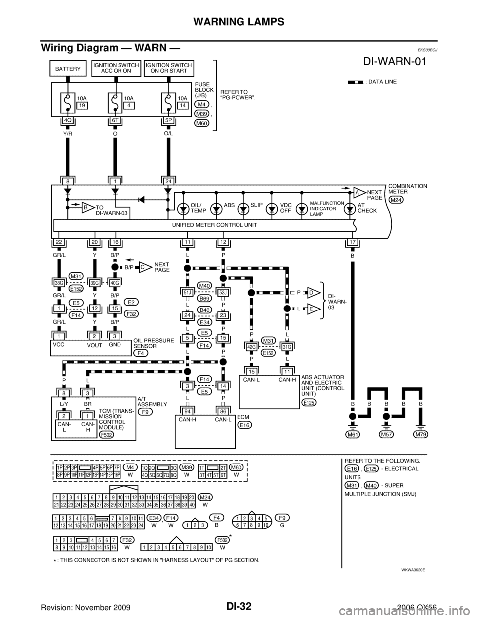
Wiring Diagram — WARN —EKS00BCJ
WKWA3620E
Page 1162 of 3383

A/T INDICATORDI-41
C
DE
F
G H
I
J
L
M A
B
DI
Revision: November 2009 2006 QX56
A/T INDICATORPFP:24814
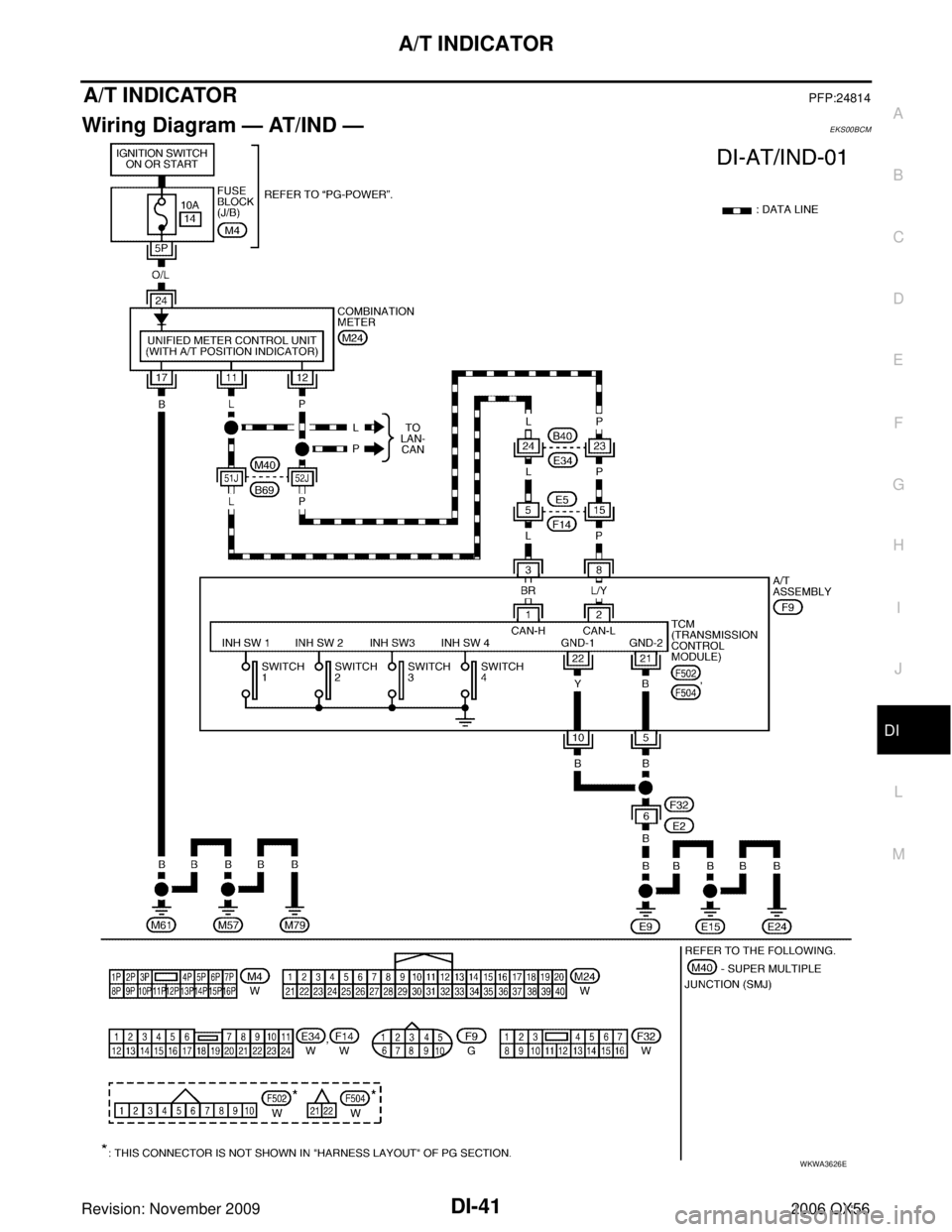
Wiring Diagram — AT/IND —EKS00BCM
WKWA3626E
Page 1167 of 3383

DI-46
WARNING CHIME
Revision: November 20092006 QX56
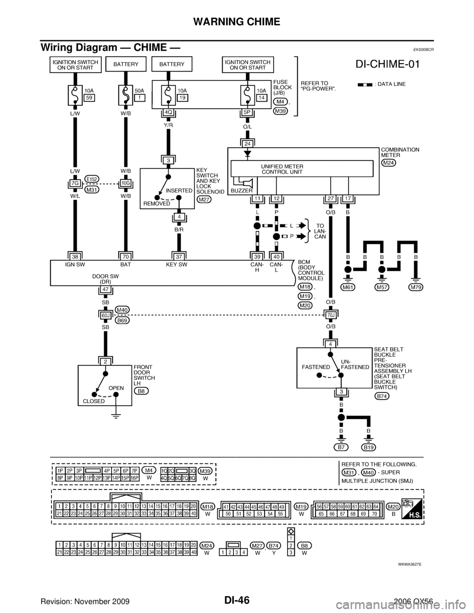
Wiring Diagram — CHIME —EKS00BCR
WKWA3627E
Page 1171 of 3383

DI-50
WARNING CHIME
Revision: November 20092006 QX56
Preliminary CheckEKS00BCV
INSPECTION FOR POWER SUPPLY AND GROUND CIRCUIT
1. CHECK FUSE AND FUSIBLE LINK
Check for blown BCM fuse or fusible link.
Refer to DI-46, "Wiring Diagram — CHIME —" .
OK or NG
OK >> GO TO 2.
NG >> If fuse is blown, be sure to eliminate cause of malfunction before installing new fuse. Refer to PG-
4, "POWER SUPPLY ROUTING CIRCUIT" .
2. CHECK POWER SUPPLY CIRCUIT
1. Disconnect BCM connectors M18 and M20.
2. Check voltage between BCM harness connector terminals and ground.
OK or NG
OK >> GO TO 3.
NG >> Check harness for open between BCM and fuse.
3. CHECK GROUND CIRCUIT
1. Turn ignition switch OFF.
2. Check continuity between BCM harness connector M20 terminal 67 and ground.
OK or NG
OK >> Inspection End.
NG >> Repair harness or connector.
Unit Power source Fuse or fusible link No.
BCM Battery
f
Ignition switch ON or START 59
TerminalsIgnition switch position
(+) (– )O FFO N
Connector Terminal
M20 70
GroundBattery volt-
age Battery volt-
age
M18 38 0VBattery volt-
age
WKIA2072E
Continuity should exist.
LIIA0915E
Page 1176 of 3383

WARNING CHIMEDI-55
C
DE
F
G H
I
J
L
M A
B
DI
Revision: November 2009 2006 QX56
3. CHECK FRONT DOOR SWITCH LH
Check continuity between front door switch LH terminal 2 and
exposed metal of switch while pressing and releasing switch.
OK or NG
OK >> Replace the BCM. Refer to BCS-20, "BCM" .
NG >> Replace the front door switch LH.
Key Warning Chime Does Not OperateEKS00BCZ
1. CHECK FUSE
Check if the key switch fuse [No. 19, located in the fuse block (J/B)] is blown. Refer to DI-46, "
Wiring Diagram
— CHIME —" .
Is the fuse blown?
YES >> Replace the fuse. Be sure to repair the cause of malfunction before installing new fuse.
NO >> GO TO 2.
2. CHECK WARNING CHIME OPERATION
With key removed from the ignition key cylinder and the front door LH open, turn the lighting switch to 1st or
2nd position.
Does warning chime sound?
YES >> GO TO 3.
NO >> Go to DI-53, "
All Warning Chimes Do Not Operate" or DI-54, "Key Warning Chime and Light
Warning Chime Do Not Operate (Seat Belt Warning Chime Does Operate)" .
When front door switch
LH is released
: Continuity should exist.
When front door switch
LH is pressed : Continuity should not
exist.
WKIA2023E
Page 1184 of 3383

REAR SONAR SYSTEMDI-63
C
DE
F
G H
I
J
L
M A
B
DI
Revision: November 2009 2006 QX56
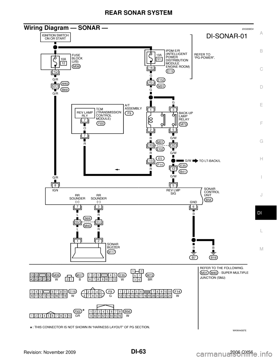
Wiring Diagram — SONAR —EKS00BD4
WKWA4087E