belt INFINITI QX56 2007 Factory Service Manual
[x] Cancel search | Manufacturer: INFINITI, Model Year: 2007, Model line: QX56, Model: INFINITI QX56 2007Pages: 3061, PDF Size: 64.56 MB
Page 2671 of 3061

CHARGING SYSTEM
SC-23
< SERVICE INFORMATION >
C
D
E
F
G
H
I
J
L
MA
B
SC
N
O
P
4. Remove the lower bracket, using power tools.
5. Remove the generator upper bolt, using power tools.
6. Remove/disconnect the generator harness connectors.
7. Remove the generator.
INSTALLATION
Installation is in the reverse order of removal.
• Install the generator and check the tension of the drive belt. Refer to EM-13, "
Checking Drive Belts".
CAUTION:
Tighten terminal nut carefully.
WKIA1390E
Terminal nut : 10.8 N·m (1.1 kg-m, 8 ft-lb)
Page 2673 of 3061

SE-1
BODY
C
D
E
F
G
H
J
K
L
M
SECTION SE
A
B
SE
N
O
P
CONTENTS
SEAT
SERVICE INFORMATION ............................3
PRECAUTIONS ...................................................3
Precaution for Supplemental Restraint System
(SRS) "AIR BAG" and "SEAT BELT PRE-TEN-
SIONER" ...................................................................
3
Precaution for Work ..................................................3
PREPARATION ...................................................4
Special Service Tool .................................................4
Commercial Service Tool ..........................................4
SQUEAK AND RATTLE TROUBLE DIAGNO-
SIS .......................................................................
5
Work Flow .................................................................5
Generic Squeak and Rattle Troubleshooting ............7
Diagnostic Worksheet ...............................................9
AUTOMATIC DRIVE POSITIONER ...................11
Component Parts and Harness Connector Loca-
tion ..........................................................................
11
System Description .................................................11
CAN Communication System Description ...............13
Schematic ...............................................................13
Wiring Diagram - AUT/DP - .....................................15
Terminal and Reference Value for BCM .................24
Driver Seat Control Unit Harness Connector Ter-
minal Layout ............................................................
25
Terminal and Reference Value for Driver Seat
Control Unit .............................................................
25
Automatic Drive Positioner Control Unit Harness
Connector Terminal Layout .....................................
28
Terminal and Reference Value for Automatic
Drive Positioner Control Unit ...................................
28
Work Flow ...............................................................30
Preliminary Check ...................................................30
BCM Power Supply and Ground Circuit Inspection
....
31
Power Supply and Ground Circuit Inspection .........31
CONSULT-II Function (AUTO DRIVE POS.) ..........32
CAN Communication Inspection Using CON-
SULT-II (Self-Diagnosis) ..........................................
35
Symptom Chart ........................................................35
Sliding Motor Circuit Inspection ...............................37
Reclining Motor LH Circuit Inspection .....................38
Lifting Motor (Front) Circuit Inspection ....................39
Lifting Motor (Rear) Circuit Inspection .....................40
Pedal Adjusting Motor Circuit Inspection .................41
Mirror Motor LH Circuit Inspection ...........................42
Mirror Motor RH Circuit Inspection ..........................44
Steering Wheel Tilt Circuit Inspection ......................45
Sliding Sensor Circuit Inspection .............................46
Reclining Sensor Circuit Inspection .........................47
Lifting Sensor (Front) Circuit Inspection ..................48
Lifting Sensor (Rear) Circuit Inspection ...................49
Pedal Adjusting Sensor Circuit Inspection ...............50
Mirror Sensor LH Circuit Inspection .........................51
Mirror Sensor RH Circuit Inspection ........................53
Steering Wheel Tilt Sensor Circuit Inspection .........54
Sliding Switch Circuit Inspection ..............................55
Reclining Switch Inspection .....................................56
Lifting Switch (Front) Circuit Inspection ...................58
Lifting Switch (Rear) Circuit Inspection ....................59
Power Seat Switch Ground Inspection ....................60
Pedal Adjusting Switch Circuit Inspection ...............61
Door Mirror Remote Control Switch (Changeover
Switch) Circuit Inspection ........................................
62
Door Mirror Remote Control Switch (Mirror
Switch) Circuit Inspection ........................................
64
Door Mirror Remote Control Switch Ground Circuit
Inspection ................................................................
65
Seat Memory Switch Circuit Inspection ...................66
Seat Memory Indicator Lamp Circuit Inspection ......67
Door Mirror Sensor Power Supply and Ground
Circuit inspection .....................................................
69
A/T Device (Park Position Switch) Circuit Inspec-
tion ...........................................................................
69
Steering Wheel Tilt Switch Circuit Inspection ..........70
Front Door Switch LH Circuit Inspection ..................72
UART Communication Line Circuit Inspection ........73
Page 2675 of 3061

PRECAUTIONS
SE-3
< SERVICE INFORMATION >
C
D
E
F
G
H
J
K
L
MA
B
SE
N
O
P
SERVICE INFORMATION
PRECAUTIONS
Precaution for Supplemental Restraint System (SRS) "AIR BAG" and "SEAT BELT
PRE-TENSIONER"
INFOID:0000000003533149
The Supplemental Restraint System such as “AIR BAG” and “SEAT BELT PRE-TENSIONER”, used along
with a front seat belt, helps to reduce the risk or severity of injury to the driver and front passenger for certain
types of collision. This system includes seat belt switch inputs and dual stage front air bag modules. The SRS
system uses the seat belt switches to determine the front air bag deployment, and may only deploy one front
air bag, depending on the severity of a collision and whether the front occupants are belted or unbelted.
Information necessary to service the system safely is included in the SRS and SB section of this Service Man-
ual.
WARNING:
• To avoid rendering the SRS inoperative, which could increase the risk of personal injury or death in
the event of a collision which would result in air bag inflation, all maintenance must be performed by
an authorized NISSAN/INFINITI dealer.
• Improper maintenance, including incorrect removal and installation of the SRS, can lead to personal
injury caused by unintentional activation of the system. For removal of Spiral Cable and Air Bag
Module, see the SRS section.
• Do not use electrical test equipment on any circuit related to the SRS unless instructed to in this
Service Manual. SRS wiring harnesses can be identified by yellow and/or orange harnesses or har-
ness connectors.
Precaution for WorkINFOID:0000000003533150
• When removing or disassembling each component, be careful not to damage or deform it. If a component
may be subject to interference, be sure to protect it with a shop cloth.
• When removing (disengaging) components with a screwdriver or similar tool, be sure to wrap the component
with a shop cloth or vinyl tape to protect it.
• Protect the removed parts with a shop cloth and keep them.
• Replace a deformed or damaged clip.
• If a part is specified as a non-reusable part, always replace it with new one.
• Be sure to tighten bolts and nuts securely to the specified torque.
• After re-installation is completed, be sure to check that each part works normally.
• Follow the steps below to clean components.
- Water soluble foul: Dip a soft cloth into lukewarm water, and wring the water out of the cloth to wipe the
fouled area.
Then rub with a soft and dry cloth.
- Oily foul: Dip a soft cloth into lukewarm water with mild detergent (concentration: within 2 to 3%), and wipe
the fouled area.
Then dip a cloth into fresh water, and wring the water out of the cloth to wipe the detergent off. Then rub with
a soft and dry cloth.
• Do not use organic solvent such as thinner, benzene, alcohol, or gasoline.
• For genuine leather seats, use a genuine leather seat cleaner.
Page 2764 of 3061

SE-92
< SERVICE INFORMATION >
SECOND SEAT
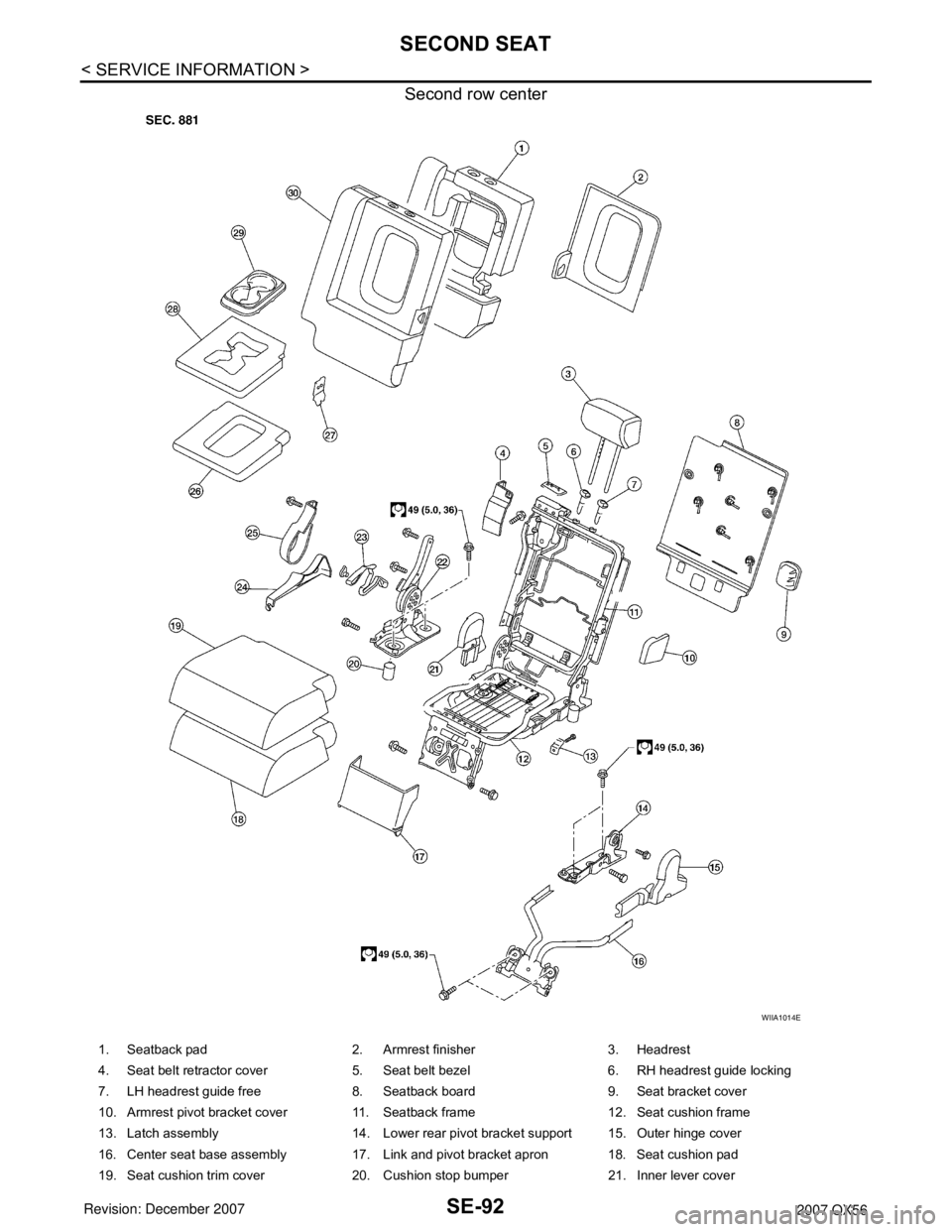
Second row center
WIIA1014E
1. Seatback pad 2. Armrest finisher 3. Headrest
4. Seat belt retractor cover 5. Seat belt bezel 6. RH headrest guide locking
7. LH headrest guide free 8. Seatback board 9. Seat bracket cover
10. Armrest pivot bracket cover 11. Seatback frame 12. Seat cushion frame
13. Latch assembly 14. Lower rear pivot bracket support 15. Outer hinge cover
16. Center seat base assembly 17. Link and pivot bracket apron 18. Seat cushion pad
19. Seat cushion trim cover 20. Cushion stop bumper 21. Inner lever cover
Page 2767 of 3061

THIRD SEAT
SE-95
< SERVICE INFORMATION >
C
D
E
F
G
H
J
K
L
MA
B
SE
N
O
P
THIRD SEAT
LH Side SeatINFOID:0000000003533214
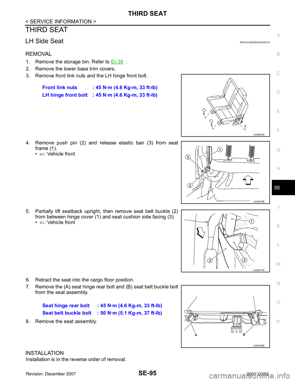
REMOVAL
1. Remove the storage bin. Refer to EI-39 .
2. Remove the lower base trim covers.
3. Remove front link nuts and the LH hinge front bolt.
4. Remove push pin (2) and release elastic ban (3) from seat
frame (1).
•⇐: Vehicle front
5. Partially lift seatback upright, then remove seat belt buckle (2)
from between hinge cover (1) and seat cushion side facing (3).
•⇐: Vehicle front
6. Retract the seat into the cargo floor position.
7. Remove the (A) seat hinge rear bolt and (B) seat belt buckle bolt
from the seat assembly.
8. Remove the seat assembly.
INSTALLATION
Installation is in the reverse order of removal.Front link nuts : 45 N·m (4.6 Kg-m, 33 ft-lb)
LH hinge front bolt : 45 N·m (4.6 Kg-m, 33 ft-lb)
LIIA2324E
LIIA2370E
LIIA2371E
Seat hinge rear bolt : 45 N·m (4.6 Kg-m, 33 ft-lb)
Seat belt buckle bolt : 50 N·m (5.1 Kg-m, 37 ft-lb)
LIIA2325E
Page 2769 of 3061

THIRD SEAT
SE-97
< SERVICE INFORMATION >
C
D
E
F
G
H
J
K
L
MA
B
SE
N
O
P
RH Side SeatINFOID:0000000003533215
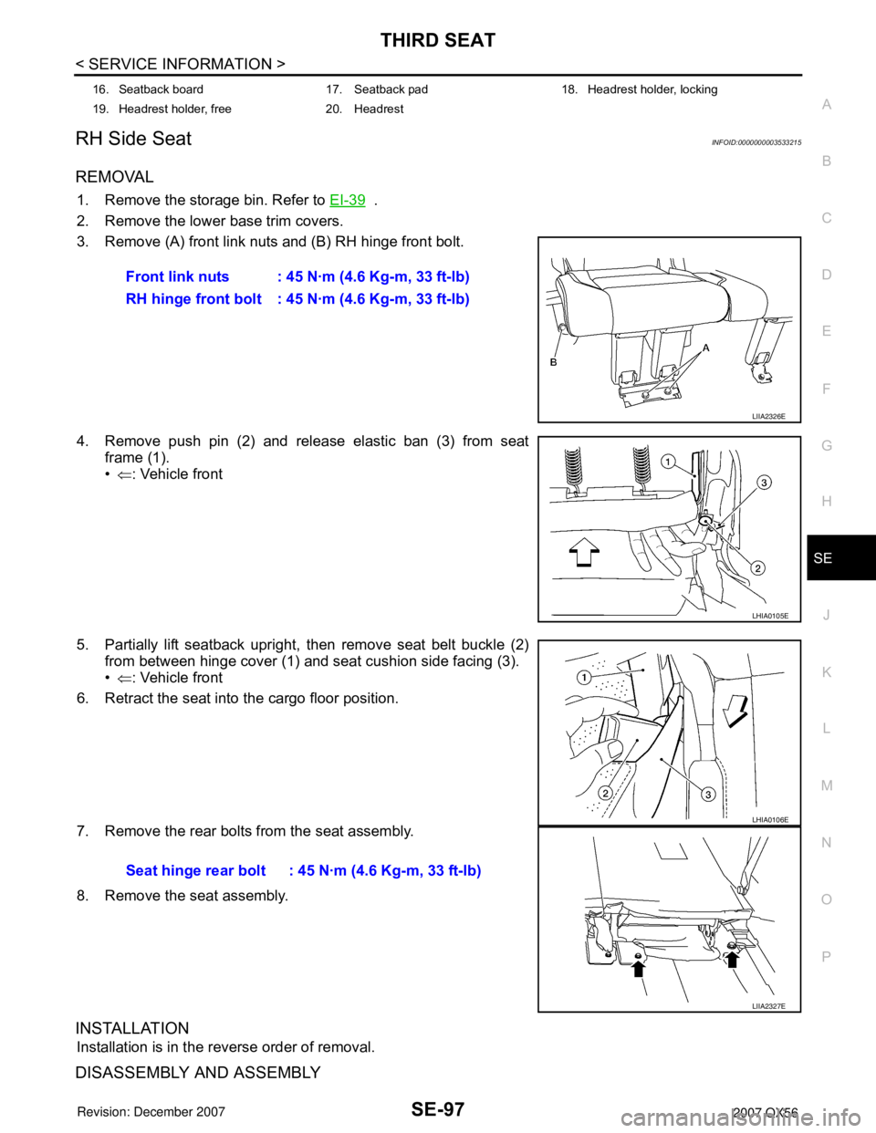
REMOVAL
1. Remove the storage bin. Refer to EI-39 .
2. Remove the lower base trim covers.
3. Remove (A) front link nuts and (B) RH hinge front bolt.
4. Remove push pin (2) and release elastic ban (3) from seat
frame (1).
•⇐: Vehicle front
5. Partially lift seatback upright, then remove seat belt buckle (2)
from between hinge cover (1) and seat cushion side facing (3).
•⇐: Vehicle front
6. Retract the seat into the cargo floor position.
7. Remove the rear bolts from the seat assembly.
8. Remove the seat assembly.
INSTALLATION
Installation is in the reverse order of removal.
DISASSEMBLY AND ASSEMBLY
16. Seatback board 17. Seatback pad 18. Headrest holder, locking
19. Headrest holder, free 20. Headrest
Front link nuts : 45 N·m (4.6 Kg-m, 33 ft-lb)
RH hinge front bolt : 45 N·m (4.6 Kg-m, 33 ft-lb)
LIIA2326E
LHIA0105E
Seat hinge rear bolt : 45 N·m (4.6 Kg-m, 33 ft-lb)
LHIA0106E
LIIA2327E
Page 2771 of 3061

SRS-1
RESTRAINTS
C
D
E
F
G
I
J
K
L
M
SECTION SRS
A
B
SRS
N
O
P
CONTENTS
SUPPLEMENTAL RESTRAINT SYSTEM (SRS)
SERVICE INFORMATION ............................2
PRECAUTIONS ...................................................2
Precaution for Supplemental Restraint System
(SRS) "AIR BAG" and "SEAT BELT PRE-TEN-
SIONER" ...................................................................
2
Precaution for SRS "AIR BAG" and "SEAT BELT
PRE-TENSIONER" Service ......................................
2
Occupant Classification System Precaution .............2
PREPARATION ...................................................3
Special Service Tool .................................................3
SUPPLEMENTAL RESTRAINT SYSTEM
(SRS) ...................................................................
4
SRS Configuration ....................................................4
Driver Air Bag Module ...............................................5
Front Passenger Air Bag Module ..............................5
Front Side Air Bag .....................................................5
Side Curtain Air Bag ..................................................5
Front Seat Belt Pre-tensioner with Load Limiter .......6
Occupant Classification System (OCS) ....................6
Direct-connect SRS Component Connectors ............6
TROUBLE DIAGNOSIS ......................................8
Trouble Diagnosis Introduction .................................8
SRS Component Parts Location .............................10
Schematic ...............................................................11
Wiring Diagram - SRS - ...........................................12
CONSULT-II Function (AIR BAG) ...........................17
CONSULT-II Function .............................................18
Self-Diagnosis Function (Without CONSULT-II) .....19
SRS Operation Check .............................................20
Trouble Diagnosis with CONSULT-II ......................21
Trouble Diagnosis without CONSULT-II .................28
Trouble Diagnosis: "AIR BAG" Warning Lamp
Does Not Turn Off ...................................................
32
Trouble Diagnosis: "AIR BAG" Warning Lamp
Does Not Turn On ...................................................
33
DRIVER AIR BAG MODULE ............................35
Removal and Installation .........................................35
SPIRAL CABLE ................................................37
Removal and Installation .........................................37
FRONT PASSENGER AIR BAG MODULE ......39
Removal and Installation .........................................39
SIDE CURTAIN AIR BAG MODULE ................42
Removal and Installation .........................................42
CRASH ZONE SENSOR ...................................44
Removal and Installation .........................................44
SIDE AIR BAG (SATELLITE) SENSOR ...........45
Removal and Installation .........................................45
FRONT SEAT BELT PRE-TENSIONER ...........46
Removal and Installation .........................................46
DIAGNOSIS SENSOR UNIT .............................47
Removal and Installation .........................................47
OCCUPANT CLASSIFICATION SYSTEM
CONTROL UNIT ................................................
48
Removal and Installation .........................................48
COLLISION DIAGNOSIS ..................................49
For Frontal Collision ................................................49
For Side and Rollover Collision ...............................50
Page 2772 of 3061

SRS-2
< SERVICE INFORMATION >
PRECAUTIONS
SERVICE INFORMATION
PRECAUTIONS
Precaution for Supplemental Restraint System (SRS) "AIR BAG" and "SEAT BELT
PRE-TENSIONER"
INFOID:0000000003532849
The Supplemental Restraint System such as “AIR BAG” and “SEAT BELT PRE-TENSIONER”, used along
with a front seat belt, helps to reduce the risk or severity of injury to the driver and front passenger for certain
types of collision. This system includes seat belt switch inputs and dual stage front air bag modules. The SRS
system uses the seat belt switches to determine the front air bag deployment, and may only deploy one front
air bag, depending on the severity of a collision and whether the front occupants are belted or unbelted.
Information necessary to service the system safely is included in the SRS and SB section of this Service Man-
ual.
WARNING:
• To avoid rendering the SRS inoperative, which could increase the risk of personal injury or death in
the event of a collision which would result in air bag inflation, all maintenance must be performed by
an authorized NISSAN/INFINITI dealer.
• Improper maintenance, including incorrect removal and installation of the SRS, can lead to personal
injury caused by unintentional activation of the system. For removal of Spiral Cable and Air Bag
Module, see the SRS section.
• Do not use electrical test equipment on any circuit related to the SRS unless instructed to in this
Service Manual. SRS wiring harnesses can be identified by yellow and/or orange harnesses or har-
ness connectors.
Precaution for SRS "AIR BAG" and "SEAT BELT PRE-TENSIONER" Service
INFOID:0000000003532850
• Do not use electrical test equipment to check SRS circuits unless instructed to in this Service Manual.
• Before servicing the SRS, turn ignition switch OFF, disconnect both battery cables and wait at least 3 min-
utes.
For approximately 3 minutes after the cables are removed, it is still possible for the air bags and seat belt
pre-tensioners to deploy. Therefore, do not work on any SRS connectors or wires until at least 3 minutes
have passed.
• The air diagnosis sensor unit must always be installed with the arrow mark “⇐” pointing toward the front of
the vehicle for proper operation. Also check air bag diagnosis sensor unit for cracks, deformities or rust
before installation and replace as required.
• The spiral cable must be aligned with the neutral position since its rotations are limited. Do not attempt to
turn steering wheel or column after removal of steering gear.
• Handle air bag module carefully. Always place driver and front passenger air bag modules with the pad side
facing upward and seat mounted front side air bag module standing with the stud bolt side facing down.
• Conduct self-diagnosis to check entire SRS for proper function after replacing any components.
• After air bag inflates, the front instrument panel assembly should be replaced if damaged.
Occupant Classification System PrecautionINFOID:0000000003532851
Replace control unit and passenger front seat cushion as an assembly.
Page 2774 of 3061

SRS-4
< SERVICE INFORMATION >
SUPPLEMENTAL RESTRAINT SYSTEM (SRS)
SUPPLEMENTAL RESTRAINT SYSTEM (SRS)
SRS ConfigurationINFOID:0000000003532853
The air bag deploys if the air bag diagnosis sensor unit is activated while the ignition switch is in the ON or
START position.
The collision modes for which supplemental restraint systems are activated are different among the SRS sys-
tems. For example, the driver air bag module, front passenger air bag module, front seat belt pre-tensioners
and seat belt buckle pre-tensioner assemblies are activated in a frontal collision but not in a side collision.
SRS configurations for some collision modes are as follows:
WHIA0215E
SRS configuration Frontal collision Left side collisionRight side colli-
sionRollover
Driver air bag module x — — —
Front passenger air bag module x — — —
Front LH seat belt pre-tensioner x — — x
Front LH seat belt buckle pre-tensioner assembly x — — x
Front RH seat belt pre-tensioner x — — x
Front RH seat belt buckle pre-tensioner assembly x — — x
Front LH side air bag module — x — —
Front RH side air bag module — — x —
LH side curtain air bag module — x — x
RH side curtain air bag module — — x x
Page 2776 of 3061

SRS-6
< SERVICE INFORMATION >
SUPPLEMENTAL RESTRAINT SYSTEM (SRS)
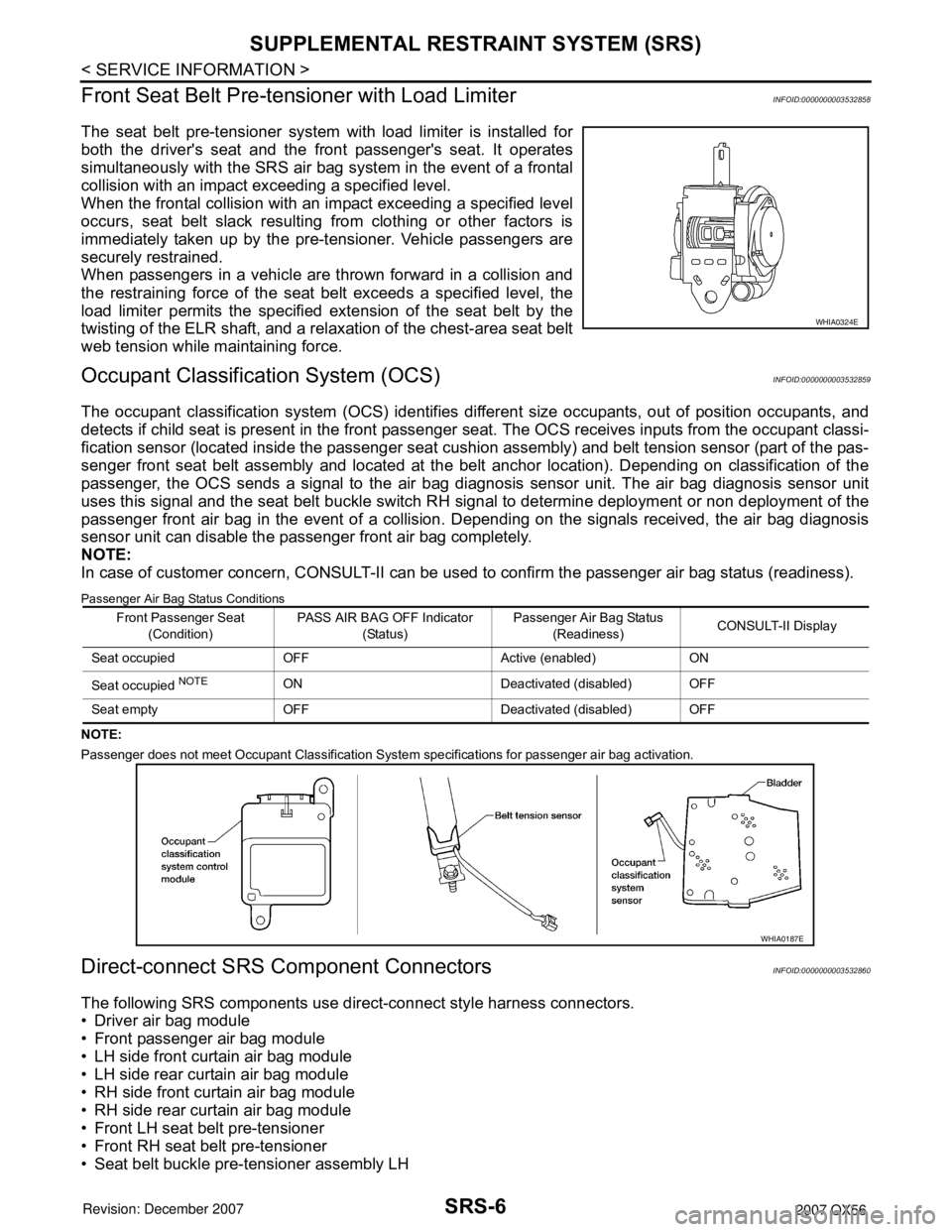
Front Seat Belt Pre-tensioner with Load Limiter
INFOID:0000000003532858
The seat belt pre-tensioner system with load limiter is installed for
both the driver's seat and the front passenger's seat. It operates
simultaneously with the SRS air bag system in the event of a frontal
collision with an impact exceeding a specified level.
When the frontal collision with an impact exceeding a specified level
occurs, seat belt slack resulting from clothing or other factors is
immediately taken up by the pre-tensioner. Vehicle passengers are
securely restrained.
When passengers in a vehicle are thrown forward in a collision and
the restraining force of the seat belt exceeds a specified level, the
load limiter permits the specified extension of the seat belt by the
twisting of the ELR shaft, and a relaxation of the chest-area seat belt
web tension while maintaining force.
Occupant Classification System (OCS)INFOID:0000000003532859
The occupant classification system (OCS) identifies different size occupants, out of position occupants, and
detects if child seat is present in the front passenger seat. The OCS receives inputs from the occupant classi-
fication sensor (located inside the passenger seat cushion assembly) and belt tension sensor (part of the pas-
senger front seat belt assembly and located at the belt anchor location). Depending on classification of the
passenger, the OCS sends a signal to the air bag diagnosis sensor unit. The air bag diagnosis sensor unit
uses this signal and the seat belt buckle switch RH signal to determine deployment or non deployment of the
passenger front air bag in the event of a collision. Depending on the signals received, the air bag diagnosis
sensor unit can disable the passenger front air bag completely.
NOTE:
In case of customer concern, CONSULT-II can be used to confirm the passenger air bag status (readiness).
Passenger Air Bag Status Conditions
NOTE:
Passenger does not meet Occupant Classification System specifications for passenger air bag activation.
Direct-connect SRS Component ConnectorsINFOID:0000000003532860
The following SRS components use direct-connect style harness connectors.
• Driver air bag module
• Front passenger air bag module
• LH side front curtain air bag module
• LH side rear curtain air bag module
• RH side front curtain air bag module
• RH side rear curtain air bag module
• Front LH seat belt pre-tensioner
• Front RH seat belt pre-tensioner
• Seat belt buckle pre-tensioner assembly LH
WHIA0324E
Front Passenger Seat
(Condition)PASS AIR BAG OFF Indicator
(Status)Passenger Air Bag Status
(Readiness)CONSULT-II Display
Seat occupied OFF Active (enabled) ON
Seat occupied
NOTEON Deactivated (disabled) OFF
Seat empty OFF Deactivated (disabled) OFF
WHIA0187E