ABS INFINITI QX56 2007 Factory Service Manual
[x] Cancel search | Manufacturer: INFINITI, Model Year: 2007, Model line: QX56, Model: INFINITI QX56 2007Pages: 3061, PDF Size: 64.56 MB
Page 2617 of 3061

REAR SUSPENSION MEMBER
RSU-27
< SERVICE INFORMATION >
C
D
F
G
H
I
J
K
L
MA
B
RSU
N
O
P
Rear Load Leveling Air Suspension System
REMOVAL
1. Use the CONSULT-II “EXHAUST SOLENOID” active test to release the air pressure from the rear load
leveling air suspension system.
2. Disconnect the electrical connectors for the height sensor and the rear load leveling air suspension com-
pressor assembly.
3. Unclip the rubber cover to access the rear load leveling air suspension compressor assembly.
4. Disconnect the rear load leveling air suspension hoses at the
rear load leveling air suspension compressor assembly.
• To disconnect the hoses, push in on the lock ring using a suit-
able tool and pull the hose out.
5. Remove both of the rear wheel and tire assemblies using power
tool.
6. Remove the brake caliper without disconnecting the brake
hoses, using power tool. Reposition the brake caliper out of the
way using a suitable wire. Refer to BR-25, "
Removal and Instal-
lation of Brake Caliper and Disc Rotor" .
CAUTION:
10. Shock absorber 11. Suspension arm 12. Lower rubber seat
13. Coil spring 14. Upper rubber seat 15. Rear suspension member
16. Spare tire bracket 17. Bound bumper
AWEIA0076ZZ
1. Rear load leveling air suspension
hose, RH2. Shock absorber, RH 3. Height sensor
4. Rear load leveling air suspension
hose, LH5. Shock absorber, LH 6. Rear load leveling air suspension
compressor assembly (includes the
bracket and rubber cover)
⇐Front
LEIA0074E
Page 2618 of 3061

RSU-28
< SERVICE INFORMATION >
REAR SUSPENSION MEMBER
• Do not crimp or stretch the brake hose when repositioning the brake caliper out of the way.
• Do not press brake pedal while the brake caliper is removed.
7. Remove the spare tire.
8. Disconnect the two rear ABS sensor electrical connectors.
9. Remove the two rear drive shafts. Refer to RAX-7, "
Removal and Installation" .
10. Remove the rear final drive. Refer to RFD-14
.
11. Remove the EVAP canister bolt from the top of the rear suspension member.
12. Disconnect the parking brake cables from the brackets on the rear suspension member.
13. Set a suitable jack to support each of the rear lower links and the
coil spring tension.
14. Remove both of the rear lower link outer bolts and lower the jack to remove the rear coil springs.
15. Remove the two bolts to disconnect the seat belt latch anchor
from the rear suspension member.
16. Disconnect both of the connecting rods from the rear stabilizer
bar.
17. Set a suitable jack under the rear suspension member.
18. Remove the six rear suspension member bolts.
19. Slowly lower the jack to remove the rear suspension member,
suspension arm, front and rear lower links and stabilizer bar as
an assembly.
20. If necessary, remove the suspension arm, spare tire bracket,
height sensor, rear load leveling air suspension hoses, stabilizer
bar, knuckle, and front and rear lower links from the rear suspension member.
INSPECTION AFTER REMOVAL
Check the rear suspension member for deformation, cracks, and other damage and replace if necessary.
INSTALLATION
Installation is in the reverse order of removal.
• When raising the rear suspension member assembly, use the
locating pins to align the rear suspension member to the vehicle
body.
LEIA0077E
LEIA0075E
LEIA0083E
Page 2620 of 3061

RSU-30
< SERVICE INFORMATION >
SHOCK ABSORBER
SHOCK ABSORBER
Removal and InstallationINFOID:0000000003532673
REMOVAL
1. Remove the wheel and tire assembly using power tool. Refer to WT-7, "Rotation".
2. Use CONSULT-II “EXHAUST SOLENOID” active test to release the air pressure from the rear load level-
ing air suspension system.
3. Remove the four clips and remove the rear fender protector, front.
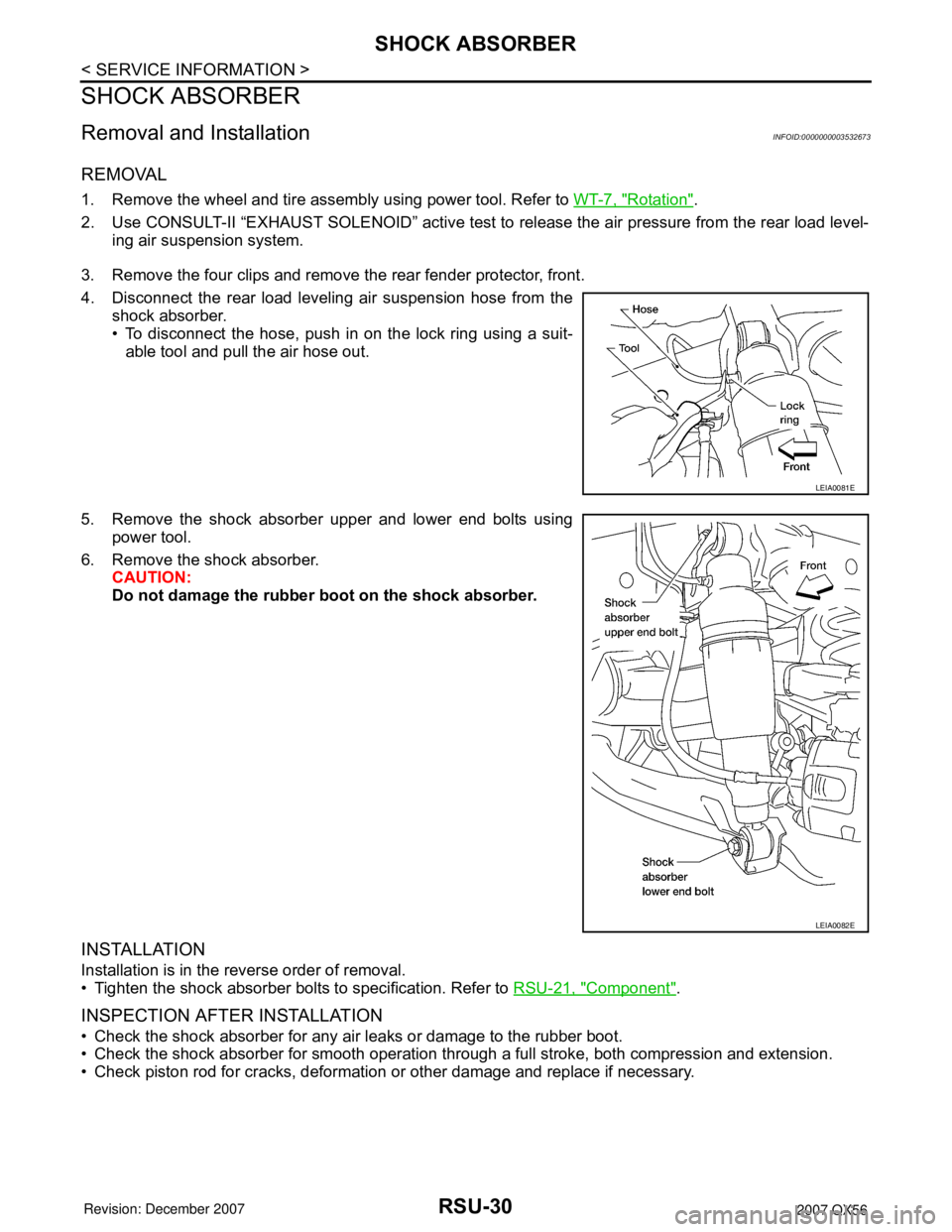
4. Disconnect the rear load leveling air suspension hose from the
shock absorber.
• To disconnect the hose, push in on the lock ring using a suit-
able tool and pull the air hose out.
5. Remove the shock absorber upper and lower end bolts using
power tool.
6. Remove the shock absorber.
CAUTION:
Do not damage the rubber boot on the shock absorber.
INSTALLATION
Installation is in the reverse order of removal.
• Tighten the shock absorber bolts to specification. Refer to RSU-21, "
Component".
INSPECTION AFTER INSTALLATION
• Check the shock absorber for any air leaks or damage to the rubber boot.
• Check the shock absorber for smooth operation through a full stroke, both compression and extension.
• Check piston rod for cracks, deformation or other damage and replace if necessary.
LEIA0081E
LEIA0082E
Page 2621 of 3061

SUSPENSION ARM
RSU-31
< SERVICE INFORMATION >
C
D
F
G
H
I
J
K
L
MA
B
RSU
N
O
P
SUSPENSION ARM
Removal and InstallationINFOID:0000000003532674
REMOVAL
1. Remove the rear suspension member assembly using power tool. Refer to RSU-26, "Removal and Instal-
lation" .
NOTE:
It is necessary to remove the rear suspension member to remove the front upper bolt from the suspension
arm.
2. Remove the shock absorber upper end bolt.
3. Remove the suspension arm upper nuts and bolts on the sus-
pension member side using power tool.
4. Remove the suspension arm pinch bolt and nut on the knuckle
side using power tool.
5. Disconnect the suspension arm from the knuckle using a soft
hammer.
CAUTION:
Do not damage the ball joint with the soft hammer.
6. Remove the suspension arm.
INSPECTION AFTER REMOVAL
• Check the suspension arm for damage, cracks, deformation and replace if necessary.
• Check the rubber bushing for damage, cracks and deformation. Replace suspension arm assembly if neces-
sary.
• Before checking, turn the ball joint at least 10 revolutions so that the ball joint is properly broken in.
LEIA0082E
LEIA0087E
Page 2623 of 3061

FRONT LOWER LINK
RSU-33
< SERVICE INFORMATION >
C
D
F
G
H
I
J
K
L
MA
B
RSU
N
O
P
FRONT LOWER LINK
Removal and InstallationINFOID:0000000003532675
REMOVAL
1. Remove the wheel and tire assembly using power tool.
2. Use CONSULT-II "EXHAUST SOLENOID" active test to release the air pressure from the rear load level-
ing air suspension system.
3. Remove the shock absorber lower end bolt.
4. Remove the adjusting bolt and nut, and the bolt and nut, from
the front lower link and rear suspension member using power
tool.
5. Remove the front lower link pinch bolt and nut on the knuckle
side using power tool.
6. Disconnect the front lower link from the knuckle using a soft
hammer.
CAUTION:
Do not damage the ball joint with the soft hammer.
7. Remove the front lower link.
INSPECTION AFTER REMOVAL
• Check the front lower link and bushing for any deformation, crack, or damage. Replace if necessary.
• Check the rubber bushing for damage, cracks and deformation. Replace the front lower link and bushing if
necessary.
• Before checking, turn the ball joint at least 10 revolutions so that the ball joint is properly broken in.
LEIA0082E
LEIA0086E
Page 2628 of 3061

RSU-38
< SERVICE INFORMATION >
REAR LOAD LEVELING AIR SUSPENSION COMPRESSOR ASSEMBLY
REAR LOAD LEVELING AIR SUSPENSION COMPRESSOR ASSEMBLY
Removal and InstallationINFOID:0000000003532678
Rear Load Leveling Air Suspension System
REMOVAL
1. Use CONSULT-II "EXHAUST SOLENOID" active test to release the air pressure from the rear load level-
ing air suspension system.
2. Disconnect the electrical connectors for the rear load leveling air suspension compressor assembly.
3. Unclip the rubber cover to access the rear load leveling air suspension compressor assembly.
4. Disconnect the rear load leveling air suspension hoses at the
rear load leveling air suspension compressor assembly.
• To disconnect the hoses, push in on the lock ring using a suit-
able tool and pull the hose out.
AWEIA0076ZZ
1. Rear load leveling air suspension
hose, RH2. Shock absorber, RH 3. Height sensor
4. Rear load leveling air suspension
hose, LH5. Shock absorber, LH 6. Rear load leveling air suspension
compressor assembly
⇐Front
LEIA0074E
Page 2630 of 3061

RSU-40
< SERVICE INFORMATION >
HEIGHT SENSOR
HEIGHT SENSOR
Removal and InstallationINFOID:0000000003532679
Rear Load Leveling Air Suspension System
REMOVAL
1. Use CONSULT-II “EXHAUST SOLENOID” active test to release the air pressure from the rear load level-
ing air suspension system.
2. Disconnect the electrical connector for the height sensor.
3. Remove the two height sensor bolts and height sensor arm
bracket bolt.
4. Remove the height sensor.
INSTALLATION
Installation is in the reverse order of removal.
AWEIA0076ZZ
1. Rear load leveling air suspension
hose, RH2. Shock absorber, RH 3. Height sensor
4. Rear load leveling air suspension
hose, LH5. Shock absorber, LH 6. Rear load leveling air suspension
compressor assembly
⇐Front
LEIA0080E
Page 2758 of 3061

SE-86
< SERVICE INFORMATION >
FRONT SEAT
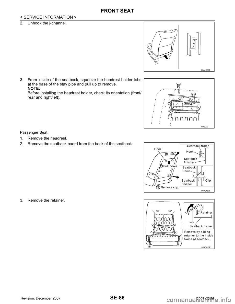
2. Unhook the j-channel.
3. From inside of the seatback, squeeze the headrest holder tabs
at the base of the stay pipe and pull up to remove.
NOTE:
Before installing the headrest holder, check its orientation (front/
rear and right/left).
Passenger Seat
1. Remove the headrest.
2. Remove the seatback board from the back of the seatback.
3. Remove the retainer.
LIIA1580E
LRS023
PIIA0163E
SIIA0113E
Page 2759 of 3061

FRONT SEAT
SE-87
< SERVICE INFORMATION >
C
D
E
F
G
H
J
K
L
MA
B
SE
N
O
P
4. From inside of the seatback, squeeze the headrest holder tabs
at the base of the stay pipe and pull up to remove.
NOTE:
Before installing the headrest holder, check its orientation (front/
rear and right/left).
Removal of seatback assembly
1. After completing the steps 1 and 2 of "Seatback Trim and Pad", remove the side air bag harness connec-
tor from the seat cushion.
2. Remove the mounting bolts (2 for each side) and seatback assembly.
Installation of seatback assembly
• Installation is in the reverse order of removal.
SEAT CUSHION TRIM AND PAD (DRIVER) OR SEAT CUSHION ASSEMBLY (PASSENGER)
CAUTION:
• Front passenger seat is equipped with an Occupant Classification System sensor and control mod-
ule. Do not disassemble front passenger seat cushion assembly or remove the trim as this will affect
the Occupant Classification System calibration.
• Always replace passenger seat cushion as an assembly.
• When removed, the passenger seat cushion must always be placed pan side UP to prevent damage.
• During installation, the wire harness clips must be reinstalled in the holes they were originally in.
Do not add clips.
• The Occupant Classification System control module can only be replaced as part of the seat cushion
assembly.
NOTE:
If the vehicle has been involved in a collision the seat must be inspected for damage. Refer to SRS-49
.
1. Remove the power seat switch knobs, power seat switch
escutcheon and lumbar switch bezel.
2. Remove the power seat and power lumbar switches.
3. Remove four bolts and the seat cushion assembly.
4. Remove the retainer on the seat cushion frame, then remove the harness connector for the seat heater.
LRS023
LIIA1581E
SIIA0503E
Page 2807 of 3061

SPIRAL CABLE
SRS-37
< SERVICE INFORMATION >
C
D
E
F
G
I
J
K
L
MA
B
SRS
N
O
P
SPIRAL CABLE
Removal and InstallationINFOID:0000000003532874
REMOVAL
CAUTION:
• Before servicing the SRS, turn ignition switch OFF, disconnect both battery cables and wait at least
3 minutes.
• When servicing the SRS, do not work from directly in front of air bag module.
1. Remove the steering wheel. Refer to PS-7
.
2. Remove the column cover upper and lower.
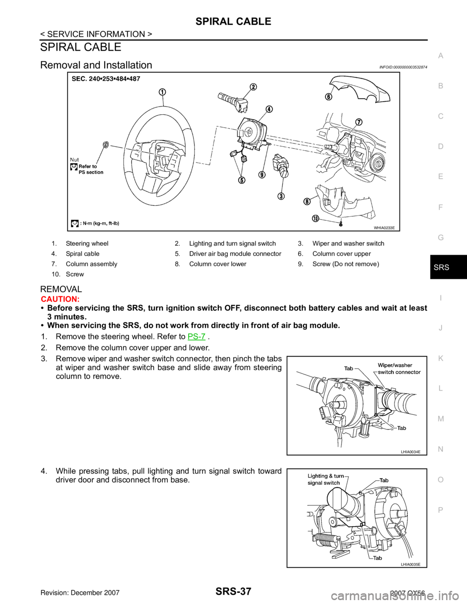
3. Remove wiper and washer switch connector, then pinch the tabs
at wiper and washer switch base and slide away from steering
column to remove.
4. While pressing tabs, pull lighting and turn signal switch toward
driver door and disconnect from base.
WHIA0233E
1. Steering wheel 2. Lighting and turn signal switch 3. Wiper and washer switch
4. Spiral cable 5. Driver air bag module connector 6. Column cover upper
7. Column assembly 8. Column cover lower 9. Screw (Do not remove)
10. Screw
LHIA0034E
LHIA0035E