coolant capacity INFINITI QX56 2007 Factory Service Manual
[x] Cancel search | Manufacturer: INFINITI, Model Year: 2007, Model line: QX56, Model: INFINITI QX56 2007Pages: 3061, PDF Size: 64.56 MB
Page 1000 of 3061

ENGINE COOLANT
CO-11
< SERVICE INFORMATION >
C
D
E
F
G
H
I
J
K
L
MA
CO
N
P O
3. Remove the vented reservoir cap and replace it with a non-vented reservoir cap before filling the cooling
system.
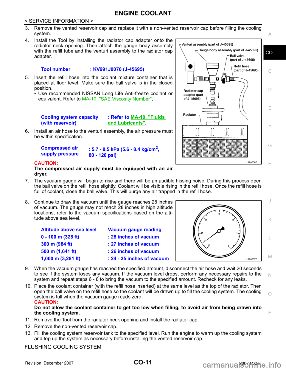
4. Install the Tool by installing the radiator cap adapter onto the
radiator neck opening. Then attach the gauge body assembly
with the refill tube and the venturi assembly to the radiator cap
adapter.
5. Insert the refill hose into the coolant mixture container that is
placed at floor level. Make sure the ball valve is in the closed
position.
• Use recommended NISSAN Long Life Anti-freeze coolant or
equivalent. Refer to MA-10, "
SAE Viscosity Number".
6. Install an air hose to the venturi assembly, the air pressure must
be within specification.
CAUTION:
The compressed air supply must be equipped with an air
dryer.
7. The vacuum gauge will begin to rise and there will be an audible hissing noise. During this process open
the ball valve on the refill hose slightly. Coolant will be visible rising in the refill hose. Once the refill hose is
full of coolant, close the ball valve. This will purge any air trapped in the refill hose.
8. Continue to draw the vacuum until the gauge reaches 28 inches
of vacuum. The gauge may not reach 28 inches in high altitude
locations, refer to the vacuum specifications based on the alti-
tude above sea level.
9. When the vacuum gauge has reached the specified amount, disconnect the air hose and wait 20 seconds
to see if the system loses any vacuum. If the vacuum level drops, perform any necessary repairs to the
system and repeat steps 6 - 8 to bring the vacuum to the specified amount. Recheck for any leaks.
10. Place the coolant container (with the refill hose inserted) at the same level as the top of the radiator. Then
open the ball valve on the refill hose so the coolant will be drawn up to fill the cooling system. The cooling
system is full when the vacuum gauge reads zero.
CAUTION:
Do not allow the coolant container to get too low when filling, to avoid air from being drawn into
the cooling system.
11. Remove the Tool from the radiator neck opening and install the radiator cap.
12. Remove the non-vented reservoir cap.
13. Fill the cooling system reservoir tank to the specified level. Run the engine to warm up the cooling system
and top up the system as necessary before installing the vented reservoir cap.
FLUSHING COOLING SYSTEM
Tool number : KV991J0070 (J-45695)
Cooling system capacity
(with reservoir): Refer to MA-10, "
Fluids
and Lubricants".
Compressed air
supply pressure: 5.7 - 8.5 kPa (5.6 - 8.4 kg/cm
2,
80 - 120 psi)
LLIA0058E
Altitude above sea level Vacuum gauge reading
0 - 100 m (328 ft) : 28 inches of vacuum
300 m (984 ft) : 27 inches of vacuum
500 m (1,641 ft) : 26 inches of vacuum
1,000 m (3,281 ft) : 24 - 25 inches of vacuum
LLIA0057E
Page 1011 of 3061

CO-22
< SERVICE INFORMATION >
SERVICE DATA AND SPECIFICATIONS (SDS)
SERVICE DATA AND SPECIFICATIONS (SDS)
Standard and LimitINFOID:0000000003531577
ENGINE COOLANT CAPACITY (APPROXIMATE)
Unit: (US gal, Imp gal)
THERMOSTAT
RADIATOR
Unit: kPa (kg/cm2, psi)
Engine coolant capacity with reservoir tank ("MAX" level) 14.4 (3 3/4, 3 1/8)
Valve opening temperature 80 - 84°C (176 - 183°F)
Maximum valve lift More than 10 mm/95°C (0.39 in/203°F)
Valve closing temperature 77°C (171°F) or higher
Reservoir cap relief pressure Standard 95 - 125 (0.97- 1.28, 14 - 18)
Leakage test pressure 137 (1.4, 20)
Page 1846 of 3061

EM-76
< SERVICE INFORMATION >
ENGINE ASSEMBLY
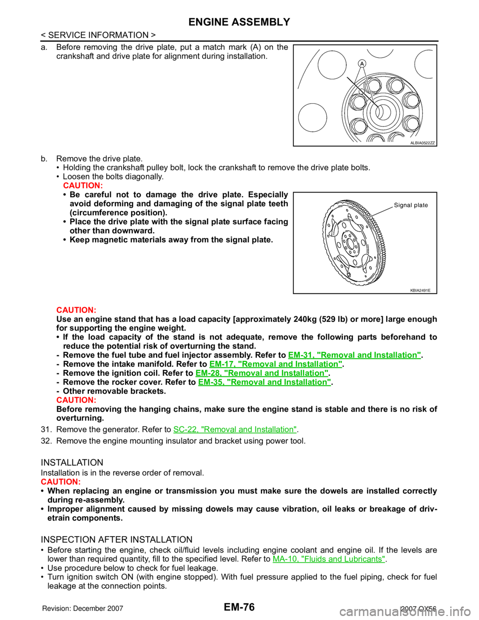
a. Before removing the drive plate, put a match mark (A) on the
crankshaft and drive plate for alignment during installation.
b. Remove the drive plate.
• Holding the crankshaft pulley bolt, lock the crankshaft to remove the drive plate bolts.
• Loosen the bolts diagonally.
CAUTION:
• Be careful not to damage the drive plate. Especially
avoid deforming and damaging of the signal plate teeth
(circumference position).
• Place the drive plate with the signal plate surface facing
other than downward.
• Keep magnetic materials away from the signal plate.
CAUTION:
Use an engine stand that has a load capacity [approximately 240kg (529 lb) or more] large enough
for supporting the engine weight.
• If the load capacity of the stand is not adequate, remove the following parts beforehand to
reduce the potential risk of overturning the stand.
- Remove the fuel tube and fuel injector assembly. Refer to EM-31, "
Removal and Installation".
- Remove the intake manifold. Refer to EM-17, "
Removal and Installation".
- Remove the ignition coil. Refer to EM-28, "
Removal and Installation".
- Remove the rocker cover. Refer to EM-35, "
Removal and Installation".
- Other removable brackets.
CAUTION:
Before removing the hanging chains, make sure the engine stand is stable and there is no risk of
overturning.
31. Remove the generator. Refer to SC-22, "
Removal and Installation".
32. Remove the engine mounting insulator and bracket using power tool.
INSTALLATION
Installation is in the reverse order of removal.
CAUTION:
• When replacing an engine or transmission you must make sure the dowels are installed correctly
during re-assembly.
• Improper alignment caused by missing dowels may cause vibration, oil leaks or breakage of driv-
etrain components.
INSPECTION AFTER INSTALLATION
• Before starting the engine, check oil/fluid levels including engine coolant and engine oil. If the levels are
lower than required quantity, fill to the specified level. Refer to MA-10, "
Fluids and Lubricants".
• Use procedure below to check for fuel leakage.
• Turn ignition switch ON (with engine stopped). With fuel pressure applied to the fuel piping, check for fuel
leakage at the connection points.
ALBIA0522ZZ
KBIA2491E
Page 2372 of 3061

MA-10
< SERVICE INFORMATION >
RECOMMENDED FLUIDS AND LUBRICANTS
RECOMMENDED FLUIDS AND LUBRICANTS
Fluids and LubricantsINFOID:0000000003533864
*1: For further details, refer to MA-10, "SAE Viscosity Number" .
*2: Using automatic transmission fluid other than Genuine NISSAN Matic J ATF will cause deterioration in driveability and automatic
transmission durability, and may damage the automatic transmission, which is not covered by the INFINITI new vehicle limited warranty.
*3: For Canada, NISSAN Automatic Transmission Fluid (ATF), DEXRON
TM III or MERCONTM or equivalent ATF may also be used.
*4: Available in mainland U.S.A. through your INFINITI dealer.
*5: For further details, see “Air conditioner specification label”.
*6: For hot climates, viscosity SAE 90 is suitable for ambient temperatures above 0° C (32° F).
*7: DEXRON
TM III, MERCONTM or equivalent may also be used. Outside the continental United States and Alaska contact a INFINITI
dealership for more information regarding suitable fluids, including recommended brand(s) of DEXRONTM III or MERCONTM Automatic
Transmission Fluid.
*8: For improved vehicle performance, INFINITI recommends the use of unleaded premium gasoline with an octane rating of at least 91
AKI (RON 96). For further details, refer to GI-4, "
Precaution for Fuel (Unleaded Premium Gasoline Required)" .
*9: See your INFINITI dealer for service for synthetic oil.
SAE Viscosity NumberINFOID:0000000003533865
GASOLINE ENGINE OIL
DescriptionCapacity (Approximate)
Recommended Fluids/Lubricants
Metric US measure Imp measure
Fuel
105.8 28 gal 23 1/4 galUnleaded gasoline with octane rating of
at least 87 AKI (RON 91) *8
Engine oil
Drain and refillWith oil filter
change6.2 6 1/2 qt 5 1/2 qt
• API Certification Mark *1
• API grade SG, Energy Conserving II or
API grade SH, SJ or SL *1
• ILSAC grade GF-II and GF-III *1 Without oil filter
change5.9 6 1/4 qt 5 1/4 qt
Dry engine (engine overhaul)
7.6 8 qt 6 3/4 qt
Cooling systemWith reservoir
at MAX level14.4 3 3/4 gal 3 1/8 galGenuine NISSAN Long Life Anti-freeze
coolant or equivalent
Automatic transmission fluid (ATF)
10.6 11 1/4 qt 9 3/8 qt Genuine NISSAN Matic J ATF *2
Rear final drive oil
1.75 3 3/4 pt 3 1/8 ptAPI GL-5 Synthetic 75W-90 Gear Oil
(Part No. 999MP-DF200P) or equivalent
*9
Transfer fluid
3.0 3 1/8 qt 2 5/8 qtGenuine NISSAN Matic D ATF (Continen-
tal U.S and Alaska) or Canada NISSAN
Automatic Transmission Fluid *7
Front final drive oil
1.6 3 3/8 pt 2 7/8 pt API GL-5 Viscosity SAE 80W-90 *6
Power steering fluid (PSF)
1.0 2 1/8 pt 1 3/4 pt Genuine NISSAN PSF or equivalent *3
Brake fluid — — —Genuine NISSAN Super Heavy Duty
Brake Fluid or equivalent,
DOT 3 (US FMVSS No. 116) *4
Brake grease — — —PBC (poly butyl cuprysil) grease or equiv-
alent
Multi-purpose grease — — — NLGI No. 2 (lithium soap base)
Windshield washer fluid
4.5 1 1/4 gal 1 galGenuine NISSAN Windshield Washer
Concentrate Cleaner & Anti-freeze or
equivalent
Air conditioning system refrigerant 1.08 ± 0.05 kg 2.38 ± 0.11 lb 2.38 ± 0.11 lb HFC-134a (R-134a) *5
Air conditioning system oil
290 m9.8 fl oz 10.2 fl ozNISSAN A/C System Oil Type S or equiv-
alent *5
Page 2376 of 3061

MA-14
< SERVICE INFORMATION >
ENGINE MAINTENANCE
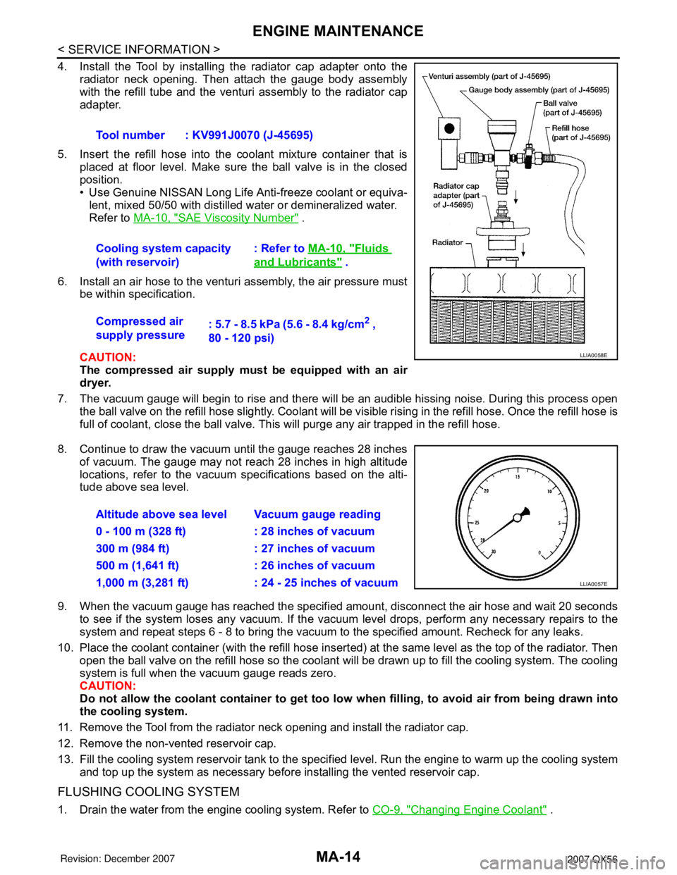
4. Install the Tool by installing the radiator cap adapter onto the
radiator neck opening. Then attach the gauge body assembly
with the refill tube and the venturi assembly to the radiator cap
adapter.
5. Insert the refill hose into the coolant mixture container that is
placed at floor level. Make sure the ball valve is in the closed
position.
• Use Genuine NISSAN Long Life Anti-freeze coolant or equiva-
lent, mixed 50/50 with distilled water or demineralized water.
Refer to MA-10, "
SAE Viscosity Number" .
6. Install an air hose to the venturi assembly, the air pressure must
be within specification.
CAUTION:
The compressed air supply must be equipped with an air
dryer.
7. The vacuum gauge will begin to rise and there will be an audible hissing noise. During this process open
the ball valve on the refill hose slightly. Coolant will be visible rising in the refill hose. Once the refill hose is
full of coolant, close the ball valve. This will purge any air trapped in the refill hose.
8. Continue to draw the vacuum until the gauge reaches 28 inches
of vacuum. The gauge may not reach 28 inches in high altitude
locations, refer to the vacuum specifications based on the alti-
tude above sea level.
9. When the vacuum gauge has reached the specified amount, disconnect the air hose and wait 20 seconds
to see if the system loses any vacuum. If the vacuum level drops, perform any necessary repairs to the
system and repeat steps 6 - 8 to bring the vacuum to the specified amount. Recheck for any leaks.
10. Place the coolant container (with the refill hose inserted) at the same level as the top of the radiator. Then
open the ball valve on the refill hose so the coolant will be drawn up to fill the cooling system. The cooling
system is full when the vacuum gauge reads zero.
CAUTION:
Do not allow the coolant container to get too low when filling, to avoid air from being drawn into
the cooling system.
11. Remove the Tool from the radiator neck opening and install the radiator cap.
12. Remove the non-vented reservoir cap.
13. Fill the cooling system reservoir tank to the specified level. Run the engine to warm up the cooling system
and top up the system as necessary before installing the vented reservoir cap.
FLUSHING COOLING SYSTEM
1. Drain the water from the engine cooling system. Refer to CO-9, "Changing Engine Coolant" . Tool number : KV991J0070 (J-45695)
Cooling system capacity
(with reservoir): Refer to MA-10, "
Fluids
and Lubricants" .
Compressed air
supply pressure: 5.7 - 8.5 kPa (5.6 - 8.4 kg/cm
2 ,
80 - 120 psi)
LLIA0058E
Altitude above sea level Vacuum gauge reading
0 - 100 m (328 ft) : 28 inches of vacuum
300 m (984 ft) : 27 inches of vacuum
500 m (1,641 ft) : 26 inches of vacuum
1,000 m (3,281 ft) : 24 - 25 inches of vacuum
LLIA0057E