MA-10 INFINITI QX56 2007 Factory User Guide
[x] Cancel search | Manufacturer: INFINITI, Model Year: 2007, Model line: QX56, Model: INFINITI QX56 2007Pages: 3061, PDF Size: 64.56 MB
Page 925 of 3061
REAR DISC BRAKE
BR-27
< SERVICE INFORMATION >
C
D
E
G
H
I
J
K
L
MA
B
BR
N
O
P
Make sure there is no wear, damage, or cracks in sliding sleeve and sliding sleeve boots, and if there are,
replace them.
ASSEMBLY
CAUTION:
Do not use NISSAN Rubber Grease (KRE00 00010, KRE00 00010 01) when assembling.
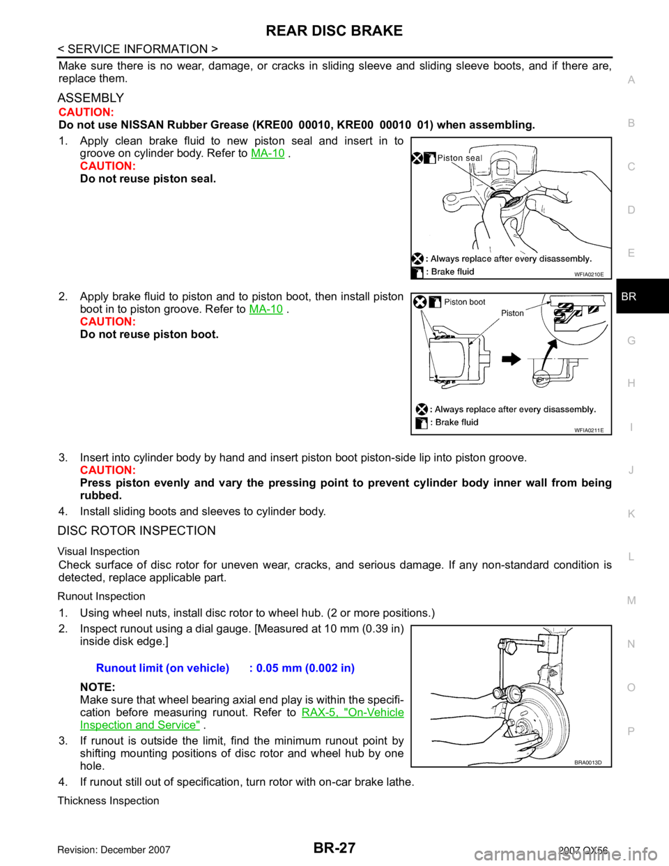
1. Apply clean brake fluid to new piston seal and insert in to
groove on cylinder body. Refer to MA-10
.
CAUTION:
Do not reuse piston seal.
2. Apply brake fluid to piston and to piston boot, then install piston
boot in to piston groove. Refer to MA-10
.
CAUTION:
Do not reuse piston boot.
3. Insert into cylinder body by hand and insert piston boot piston-side lip into piston groove.
CAUTION:
Press piston evenly and vary the pressing point to prevent cylinder body inner wall from being
rubbed.
4. Install sliding boots and sleeves to cylinder body.
DISC ROTOR INSPECTION
Visual Inspection
Check surface of disc rotor for uneven wear, cracks, and serious damage. If any non-standard condition is
detected, replace applicable part.
Runout Inspection
1. Using wheel nuts, install disc rotor to wheel hub. (2 or more positions.)
2. Inspect runout using a dial gauge. [Measured at 10 mm (0.39 in)
inside disk edge.]
NOTE:
Make sure that wheel bearing axial end play is within the specifi-
cation before measuring runout. Refer to RAX-5, "
On-Vehicle
Inspection and Service" .
3. If runout is outside the limit, find the minimum runout point by
shifting mounting positions of disc rotor and wheel hub by one
hole.
4. If runout still out of specification, turn rotor with on-car brake lathe.
Thickness Inspection
WFIA0210E
WFIA0211E
Runout limit (on vehicle) : 0.05 mm (0.002 in)
BRA0013D
Page 927 of 3061

SERVICE DATA AND SPECIFICATIONS (SDS)
BR-29
< SERVICE INFORMATION >
C
D
E
G
H
I
J
K
L
MA
B
BR
N
O
P
SERVICE DATA AND SPECIFICATIONS (SDS)
General SpecificationINFOID:0000000003532748
Unit: mm (in)
Brake PedalINFOID:0000000003532749
Unit: mm (in)
Front brake Brake model AD41VA
Rotor outer diameter × thickness 350 x 30 (13.78 x 1.18)
Pad Length × width × thickness 151.6 x 56.5 x 12.0 (5.97 x 2.22 x 0.476)
Cylinder bore diameter 51 (2.01)
Rear brake Brake model AD14VE
Rotor outer diameter × thickness 320 x 14 (12.60 x 0.551)
Pad Length × width × thickness 83.0 x 33.0 x 12.13 (3.268 x 1.299 x 0.478)
Cylinder bore diameter 48 (1.89)
Control valve Valve model Electric brake force distribution
Brake booster Booster model C215T
Diaphragm diameter 215 (8.46)
Recommended brake fluid Refer to MA-10
Free height "H"182.3 - 192.3 mm (7.18 - 7.57 in)
Depressed pedal height "D" [under a force of 490 N (50 kg-f, 110 lb-f) with engine
running]More than 90.3 mm (3.55 in)
Clearance between pedal stopper and threaded end of stop lamp switch and
ASCD switch "C
1 " or “C2 ”0.74 - 1.96 mm (0.029 - 0.077 in)
Pedal play "A"3 - 11 mm (0.12 - 0.43 in)
WFIA0160E
Page 931 of 3061
![INFINITI QX56 2007 Factory User Guide PRECAUTIONS
BRC-3
< SERVICE INFORMATION >[VDC/TCS/ABS]
C
D
E
G
H
I
J
K
L
MA
B
BRC
N
O
P
SERVICE INFORMATION
PRECAUTIONS
Precaution for Supplemental Restraint System (SRS) "AIR BAG" and "SEAT BELT
PRE INFINITI QX56 2007 Factory User Guide PRECAUTIONS
BRC-3
< SERVICE INFORMATION >[VDC/TCS/ABS]
C
D
E
G
H
I
J
K
L
MA
B
BRC
N
O
P
SERVICE INFORMATION
PRECAUTIONS
Precaution for Supplemental Restraint System (SRS) "AIR BAG" and "SEAT BELT
PRE](/img/42/57029/w960_57029-930.png)
PRECAUTIONS
BRC-3
< SERVICE INFORMATION >[VDC/TCS/ABS]
C
D
E
G
H
I
J
K
L
MA
B
BRC
N
O
P
SERVICE INFORMATION
PRECAUTIONS
Precaution for Supplemental Restraint System (SRS) "AIR BAG" and "SEAT BELT
PRE-TENSIONER"
INFOID:0000000003532761
The Supplemental Restraint System such as “AIR BAG” and “SEAT BELT PRE-TENSIONER”, used along
with a front seat belt, helps to reduce the risk or severity of injury to the driver and front passenger for certain
types of collision. This system includes seat belt switch inputs and dual stage front air bag modules. The SRS
system uses the seat belt switches to determine the front air bag deployment, and may only deploy one front
air bag, depending on the severity of a collision and whether the front occupants are belted or unbelted.
Information necessary to service the system safely is included in the SRS and SB section of this Service Man-
ual.
WARNING:
• To avoid rendering the SRS inoperative, which could increase the risk of personal injury or death in
the event of a collision which would result in air bag inflation, all maintenance must be performed by
an authorized NISSAN/INFINITI dealer.
• Improper maintenance, including incorrect removal and installation of the SRS, can lead to personal
injury caused by unintentional activation of the system. For removal of Spiral Cable and Air Bag
Module, see the SRS section.
• Do not use electrical test equipment on any circuit related to the SRS unless instructed to in this
Service Manual. SRS wiring harnesses can be identified by yellow and/or orange harnesses or har-
ness connectors.
Precaution for Brake SystemINFOID:0000000003532762
CAUTION:
• Refer to MA-10
for recommended brake fluid.
• Never reuse drained brake fluid.
• Be careful not to splash brake fluid on painted areas; it may cause paint damage. If brake fluid is
splashed on painted areas, wash it away with water immediately.
• To clean or wash all parts of master cylinder and disc brake caliper, use clean brake fluid.
• Never use mineral oils such as gasoline or kerosene. They will ruin rubber parts of the hydraulic sys-
tem.
• Use flare nut wrench when removing and installing brake
tube.
• If a brake fluid leak is found, the part must be disassembled
without fail. Then it has to be replaced with a new one if a
defect exists.
• Turn the ignition switch OFF and remove the connector of the
ABS actuator and electric unit (control unit) or the battery ter-
minal before performing the work.
• Always torque brake lines when installing.
• Burnish the brake contact surfaces after refinishing or replac-
ing rotors, after replacing pads, or if a soft pedal occurs at
very low mileage.
Refer to BR-20, "
Disassembly and Assembly of Brake Caliper" (front disc brake) or BR-26, "Brake
Caliper" (rear disc brake).
WARNING:
• Clean brake pads and shoes with a waste cloth, then wipe with a dust collector.
Precaution When Using CONSULT-IIINFOID:0000000003532763
When connecting CONSULT-II to data link connector, connect them through CONSULT-II CONVERTER.
CAUTION:
If CONSULT-II is used with no connection of CONSULT-II CONVERTER, malfunctions might be
detected in self-diagnosis depending on control unit which carries out CAN communication.
CHECK POINTS FOR USING CONSULT-II
1. Has CONSULT-II been used without connecting CONSULT-II CONVERTER on this vehicle?
SBR686C
Page 984 of 3061
![INFINITI QX56 2007 Factory User Guide BRC-56
< SERVICE INFORMATION >[VDC/TCS/ABS]
WHEEL SENSOR
WHEEL SENSOR
Removal and InstallationINFOID:0000000003532811
REMOVAL
1. Remove wheel sensor bolt.
• When removing the front wheel sensor, fir INFINITI QX56 2007 Factory User Guide BRC-56
< SERVICE INFORMATION >[VDC/TCS/ABS]
WHEEL SENSOR
WHEEL SENSOR
Removal and InstallationINFOID:0000000003532811
REMOVAL
1. Remove wheel sensor bolt.
• When removing the front wheel sensor, fir](/img/42/57029/w960_57029-983.png)
BRC-56
< SERVICE INFORMATION >[VDC/TCS/ABS]
WHEEL SENSOR
WHEEL SENSOR
Removal and InstallationINFOID:0000000003532811
REMOVAL
1. Remove wheel sensor bolt.
• When removing the front wheel sensor, first remove the disc rotor to gain access to the front wheel sen-
sor bolt. Refer to BR-19, "
Removal and Installation of Brake Caliper and Disc Rotor" .
• When removing the rear wheel sensor, first remove the rear hub and bearing assembly to gain access to
the rear wheel sensor bolt. Refer to FA X - 5 , "
Removal and Installation" .
2. Pull out the sensor, being careful to turn it as little as possible.
CAUTION:
• Do not pull on the sensor harness.
3. Disconnect wheel sensor harness electrical connector, then remove harness from attaching points.
INSTALLATION
Installation is in the reverse order of removal. Tighten wheel sensor bolt to specification.
CAUTION:
Installation should be performed while paying attention to the following.
• Inspect wheel sensor O-ring, replace sensor assembly if damaged.
• Before installing wheel sensor, make sure no foreign materials (such as iron fragments) are adhered
to the pick-up part of the sensor, to the inside of the sensor hole or on the rotor mating surface.
• Apply a coat of suitable grease to the wheel sensor O-ring and hole. Refer to MA-10
.
WFIA0376E
Page 987 of 3061
![INFINITI QX56 2007 Factory User Guide ACTUATOR AND ELECTRIC UNIT (ASSEMBLY)
BRC-59
< SERVICE INFORMATION >[VDC/TCS/ABS]
C
D
E
G
H
I
J
K
L
MA
B
BRC
N
O
P
• After installation of the ABS actuator and electric unit (control unit), refill t INFINITI QX56 2007 Factory User Guide ACTUATOR AND ELECTRIC UNIT (ASSEMBLY)
BRC-59
< SERVICE INFORMATION >[VDC/TCS/ABS]
C
D
E
G
H
I
J
K
L
MA
B
BRC
N
O
P
• After installation of the ABS actuator and electric unit (control unit), refill t](/img/42/57029/w960_57029-986.png)
ACTUATOR AND ELECTRIC UNIT (ASSEMBLY)
BRC-59
< SERVICE INFORMATION >[VDC/TCS/ABS]
C
D
E
G
H
I
J
K
L
MA
B
BRC
N
O
P
• After installation of the ABS actuator and electric unit (control unit), refill the brake system with new brake
fluid. Refer to MA-10
. Then bleed the air from the system. Refer to BR-8, "Bleeding Brake System" .
CAUTION:
• Never reuse drained brake fluid.
• Adjust the steering angle sensor. Refer to BRC-54, "
Adjustment of Steering Angle Sensor Neutral
Position" .
• Calibrate the yaw rate/side/decel G sensor. Refer to BRC-54, "
Calibration of Decel G Sensor" .
Page 1000 of 3061
ENGINE COOLANT
CO-11
< SERVICE INFORMATION >
C
D
E
F
G
H
I
J
K
L
MA
CO
N
P O
3. Remove the vented reservoir cap and replace it with a non-vented reservoir cap before filling the cooling
system.
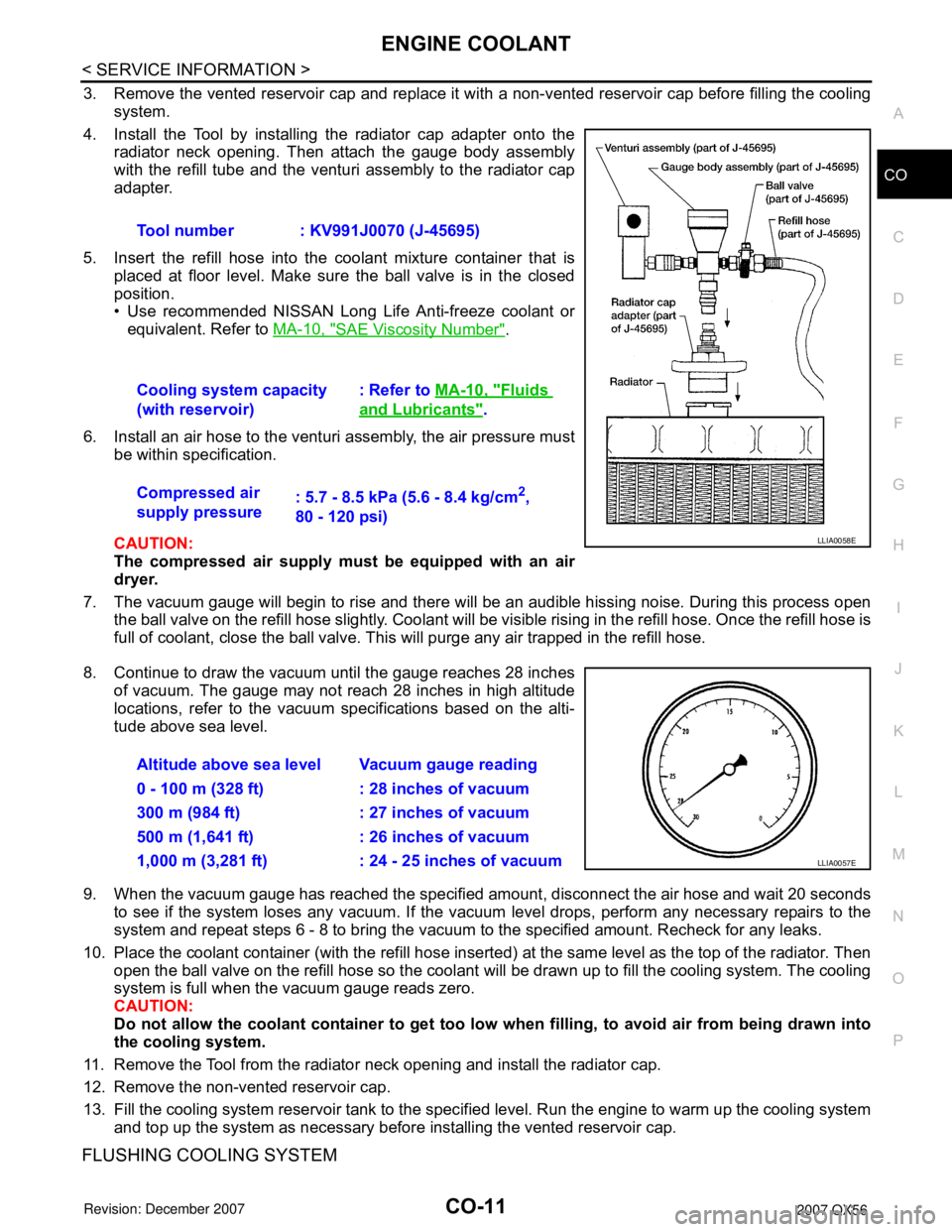
4. Install the Tool by installing the radiator cap adapter onto the
radiator neck opening. Then attach the gauge body assembly
with the refill tube and the venturi assembly to the radiator cap
adapter.
5. Insert the refill hose into the coolant mixture container that is
placed at floor level. Make sure the ball valve is in the closed
position.
• Use recommended NISSAN Long Life Anti-freeze coolant or
equivalent. Refer to MA-10, "
SAE Viscosity Number".
6. Install an air hose to the venturi assembly, the air pressure must
be within specification.
CAUTION:
The compressed air supply must be equipped with an air
dryer.
7. The vacuum gauge will begin to rise and there will be an audible hissing noise. During this process open
the ball valve on the refill hose slightly. Coolant will be visible rising in the refill hose. Once the refill hose is
full of coolant, close the ball valve. This will purge any air trapped in the refill hose.
8. Continue to draw the vacuum until the gauge reaches 28 inches
of vacuum. The gauge may not reach 28 inches in high altitude
locations, refer to the vacuum specifications based on the alti-
tude above sea level.
9. When the vacuum gauge has reached the specified amount, disconnect the air hose and wait 20 seconds
to see if the system loses any vacuum. If the vacuum level drops, perform any necessary repairs to the
system and repeat steps 6 - 8 to bring the vacuum to the specified amount. Recheck for any leaks.
10. Place the coolant container (with the refill hose inserted) at the same level as the top of the radiator. Then
open the ball valve on the refill hose so the coolant will be drawn up to fill the cooling system. The cooling
system is full when the vacuum gauge reads zero.
CAUTION:
Do not allow the coolant container to get too low when filling, to avoid air from being drawn into
the cooling system.
11. Remove the Tool from the radiator neck opening and install the radiator cap.
12. Remove the non-vented reservoir cap.
13. Fill the cooling system reservoir tank to the specified level. Run the engine to warm up the cooling system
and top up the system as necessary before installing the vented reservoir cap.
FLUSHING COOLING SYSTEM
Tool number : KV991J0070 (J-45695)
Cooling system capacity
(with reservoir): Refer to MA-10, "
Fluids
and Lubricants".
Compressed air
supply pressure: 5.7 - 8.5 kPa (5.6 - 8.4 kg/cm
2,
80 - 120 psi)
LLIA0058E
Altitude above sea level Vacuum gauge reading
0 - 100 m (328 ft) : 28 inches of vacuum
300 m (984 ft) : 27 inches of vacuum
500 m (1,641 ft) : 26 inches of vacuum
1,000 m (3,281 ft) : 24 - 25 inches of vacuum
LLIA0057E
Page 1553 of 3061
EC-470
< SERVICE INFORMATION >
DTC P1217 ENGINE OVER TEMPERATURE
On Board Diagnosis Logic
INFOID:0000000003531991
If the cooling fan or another component in the cooling system malfunctions, engine coolant temperature will
rise.
When the engine coolant temperature reaches an abnormally high temperature condition, a malfunction is
indicated.
This self-diagnosis has the one trip detection logic.
CAUTION:
When a malfunction is indicated, be sure to replace the coolant. Refer to CO-9, "
Changing Engine
Coolant". Also, replace the engine oil. Refer to LU-9, "Changing Engine Oil".
1. Fill radiator with coolant up to specified level with a filling speed of 2 liters per minute. Be sure to
use coolant with the proper mixture ratio. Refer to MA-10, "
SAE Viscosity Number".
2. After refilling coolant, run engine to ensure that no water-flow noise is emitted.
Overall Function CheckINFOID:0000000003531992
Use this procedure to check the overall function of the cooling fan. During this check, a DTC might not be con-
firmed.
WARNING:
Never remove the radiator cap and/or reservoir tank cap when the engine is hot. Serious burns could
be caused by high pressure fluid escaping from the radiator and/or reservoir tank.
Wrap a thick cloth around cap. Carefully remove the cap by turning it a quarter turn to allow built-up
pressure to escape. Then turn the cap all the way off.
WITH CONSULT-II
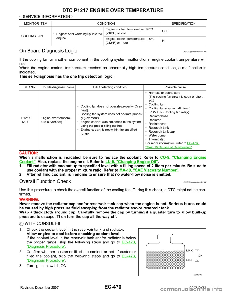
1. Check the coolant level in the reservoir tank and radiator.
Allow engine to cool before checking coolant level.
If the coolant level in the reservoir tank and/or radiator is below
the proper range, skip the following steps and go to EC-473,
"Diagnosis Procedure".
2. Confirm whether customer filled the coolant or not. If customer
filled the coolant, skip the following steps and go to EC-473,
"Diagnosis Procedure".
3. Turn ignition switch ON.
COOLING FAN• Engine: After warming up, idle the
engineEngine coolant temperature: 99°C
(210°F) or lessOFF
Engine coolant temperature: 100°C
(212°F) or moreHI MONITOR ITEM CONDITION SPECIFICATION
DTC No. Trouble diagnosis name DTC detecting condition Possible cause
P1217
1217Engine over tempera-
ture (Overheat)• Cooling fan does not operate properly (Over-
heat).
• Cooling fan system does not operate proper-
ly (Overheat).
• Engine coolant was not added to the system
using the proper filling method.
• Engine coolant is not within the specified
range.• Harness or connectors
(The cooling fan circuit is open or short-
ed.)
• Cooling fan
• Cooling fan (crankshaft diven)
• IPDM E/R (Cooling fan relay)
•Radiator hose
•Radiator
•Radiator cap
• Reservoir tank
• Reservoir tank cap
• Water pump
•Thermostat
For more information, refer to EC-476,
"Main 13 Causes of Overheating".
SEF621W
Page 1559 of 3061

EC-476
< SERVICE INFORMATION >
DTC P1217 ENGINE OVER TEMPERATURE
Main 13 Causes of Overheating
INFOID:0000000003531995
*1: Turn the ignition switch ON.
*2: Engine running at 3,000 rpm for 10 minutes.
*3: Drive at 90 km/h (55 MPH) for 30 minutes and then let idle for 10 minutes.
*4: After 60 minutes of cool down time.
For more information, refer to CO-6
.
Component InspectionINFOID:0000000003531996
COOLING FAN MOTOR
1. Disconnect cooling fan motor harness connector.
2. Supply cooling fan motor terminals with battery voltage and
check operation.
Cooling fan motor should operate.
If NG, replace cooling fan motor.
Engine Step Inspection item Equipment Standard Reference page
OFF 1 • Blocked radiator
• Blocked condenser
• Blocked radiator grille
• Blocked bumper• Visual No blocking —
2 • Coolant mixture • Coolant tester 50 - 50% coolant mixtureMA-10
3 • Coolant level • Visual Coolant up to MAX level in
reservoir tank and radiator
filler neckMA-12, "Changing Engine
Coolant"
4 • Reservoir tank cap • Pressure tester 95 - 125 kPa
(0.97 - 1.28 kg/cm2, 14 -
18 psi) (Limit)CO-9, "
Inspection"
ON*25 • Coolant leaks • Visual No leaksCO-9, "Inspection"
ON*26 • Thermostat • Touch the upper and
lower radiator hosesBoth hoses should be hotCO-20
ON*17 • Cooling fan • CONSULT-II Operating See trouble diagnosis for
DTC P1217 (EC-469
).
OFF 8 • Combustion gas leak • Color checker chemical
tester 4 Gas analyzerNegative —
ON*
39 • Coolant temperature
gauge• Visual Gauge less than 3/4 when
driving—
• Coolant overflow to res-
ervoir tank• Visual No overflow during driving
and idlingMA-12, "
Changing Engine
Coolant"
OFF*410 • Coolant return from res-
ervoir tank to radiator• Visual Should be initial level in
reservoir tankMA-12, "Changing Engine
Coolant"
OFF 12 • Cylinder head • Straight gauge feeler
gauge0.1 mm (0.004 in) Maxi-
mum distortion (warping)EM-69, "Inspection After
Disassembly"
13 • Cylinder block and pis-
tons• Visual No scuffing on cylinder
walls or pistonEM-93, "Inspection After
Disassembly"
AWBIA0529ZZ
Page 1846 of 3061
EM-76
< SERVICE INFORMATION >
ENGINE ASSEMBLY
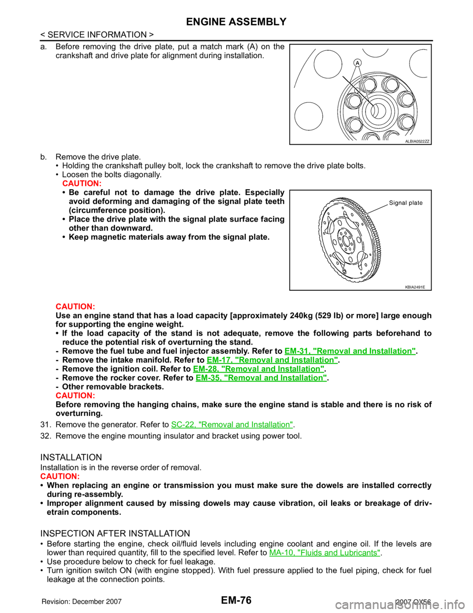
a. Before removing the drive plate, put a match mark (A) on the
crankshaft and drive plate for alignment during installation.
b. Remove the drive plate.
• Holding the crankshaft pulley bolt, lock the crankshaft to remove the drive plate bolts.
• Loosen the bolts diagonally.
CAUTION:
• Be careful not to damage the drive plate. Especially
avoid deforming and damaging of the signal plate teeth
(circumference position).
• Place the drive plate with the signal plate surface facing
other than downward.
• Keep magnetic materials away from the signal plate.
CAUTION:
Use an engine stand that has a load capacity [approximately 240kg (529 lb) or more] large enough
for supporting the engine weight.
• If the load capacity of the stand is not adequate, remove the following parts beforehand to
reduce the potential risk of overturning the stand.
- Remove the fuel tube and fuel injector assembly. Refer to EM-31, "
Removal and Installation".
- Remove the intake manifold. Refer to EM-17, "
Removal and Installation".
- Remove the ignition coil. Refer to EM-28, "
Removal and Installation".
- Remove the rocker cover. Refer to EM-35, "
Removal and Installation".
- Other removable brackets.
CAUTION:
Before removing the hanging chains, make sure the engine stand is stable and there is no risk of
overturning.
31. Remove the generator. Refer to SC-22, "
Removal and Installation".
32. Remove the engine mounting insulator and bracket using power tool.
INSTALLATION
Installation is in the reverse order of removal.
CAUTION:
• When replacing an engine or transmission you must make sure the dowels are installed correctly
during re-assembly.
• Improper alignment caused by missing dowels may cause vibration, oil leaks or breakage of driv-
etrain components.
INSPECTION AFTER INSTALLATION
• Before starting the engine, check oil/fluid levels including engine coolant and engine oil. If the levels are
lower than required quantity, fill to the specified level. Refer to MA-10, "
Fluids and Lubricants".
• Use procedure below to check for fuel leakage.
• Turn ignition switch ON (with engine stopped). With fuel pressure applied to the fuel piping, check for fuel
leakage at the connection points.
ALBIA0522ZZ
KBIA2491E
Page 1896 of 3061
FAX-10
< SERVICE INFORMATION >
DRIVE SHAFT
• Check the ball sliding surface for any compression scars, cracks, or fractures.
• Check for any damage to the serrated part.
CAUTION:
If any defective conditions are found, install a new housing, ball cage, steel ball, and inner race as a
set.
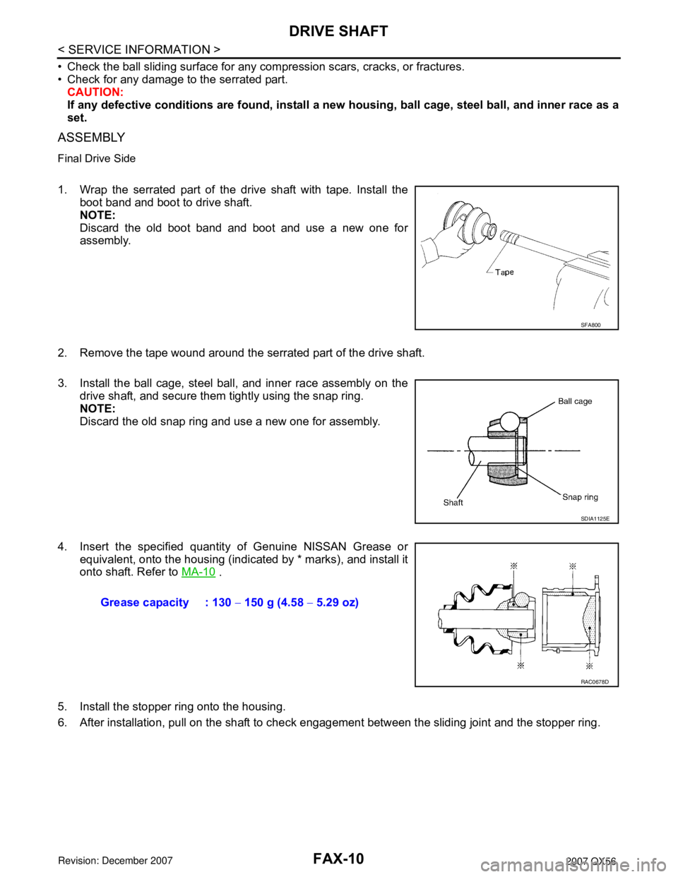
ASSEMBLY
Final Drive Side
1. Wrap the serrated part of the drive shaft with tape. Install the
boot band and boot to drive shaft.
NOTE:
Discard the old boot band and boot and use a new one for
assembly.
2. Remove the tape wound around the serrated part of the drive shaft.
3. Install the ball cage, steel ball, and inner race assembly on the
drive shaft, and secure them tightly using the snap ring.
NOTE:
Discard the old snap ring and use a new one for assembly.
4. Insert the specified quantity of Genuine NISSAN Grease or
equivalent, onto the housing (indicated by * marks), and install it
onto shaft. Refer to MA-10
.
5. Install the stopper ring onto the housing.
6. After installation, pull on the shaft to check engagement between the sliding joint and the stopper ring.
SFA800
SDIA1125E
Grease capacity : 130 − 150 g (4.58 − 5.29 oz)
RAC0678D