MA-10 INFINITI QX56 2007 Factory Service Manual
[x] Cancel search | Manufacturer: INFINITI, Model Year: 2007, Model line: QX56, Model: INFINITI QX56 2007Pages: 3061, PDF Size: 64.56 MB
Page 79 of 3061

PRECAUTIONS
AT-9
< SERVICE INFORMATION >
D
E
F
G
H
I
J
K
L
MA
B
AT
N
O
P
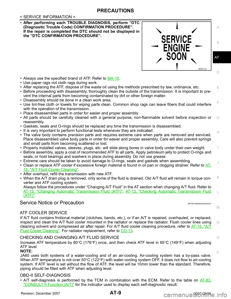
•After performing each TROUBLE DIAGNOSIS, perform “DTC
(Diagnostic Trouble Code) CONFIRMATION PROCEDURE”.
If the repair is completed the DTC should not be displayed in
the “DTC CONFIRMATION PROCEDURE”.
• Always use the specified brand of ATF. Refer to MA-10
.
• Use paper rags not cloth rags during work.
• After replacing the ATF, dispose of the waste oil using the methods prescribed by law, ordinance, etc.
• Before proceeding with disassembly, thoroughly clean the outside of the transmission. It is important to pre-
vent the internal parts from becoming contaminated by dirt or other foreign matter.
• Disassembly should be done in a clean work area.
• Use lint-free cloth or towels for wiping parts clean. Common shop rags can leave fibers that could interfere
with the operation of the transmission.
• Place disassembled parts in order for easier and proper assembly.
• All parts should be carefully cleaned with a general purpose, non-flammable solvent before inspection or
reassembly.
• Gaskets, seals and O-rings should be replaced any time the transmission is disassembled.
• It is very important to perform functional tests whenever they are indicated.
• The valve body contains precision parts and requires extreme care when parts are removed and serviced.
Place disassembled valve body parts in order for easier and proper assembly. Care will also prevent springs
and small parts from becoming scattered or lost.
• Properly installed valves, sleeves, plugs, etc. will slide along bores in valve body under their own weight.
• Before assembly, apply a coat of recommended ATF to all parts. Apply petroleum jelly to protect O-rings and
seals, or hold bearings and washers in place during assembly. Do not use grease.
• Extreme care should be taken to avoid damage to O-rings, seals and gaskets when assembling.
• Clean or replace ATF cooler if excessive foreign material is found in oil pan or clogging strainer. Refer to AT-
15, "A/T Fluid Cooler Cleaning".
• After overhaul, refill the transmission with new ATF.
• When the A/T drain plug is removed, only some of the fluid is drained. Old A/T fluid will remain in torque con-
verter and ATF cooling system.
Always follow the procedures under “Changing A/T Fluid” in the AT section when changing A/T fluid. Refer to
AT-13, "
Changing Automatic Transmission Fluid (ATF)", AT-13, "Checking Automatic Transmission Fluid
(ATF)".
Service Notice or PrecautionINFOID:0000000003532221
ATF COOLER SERVICE
If A/T fluid contains frictional material (clutches, bands, etc.), or if an A/T is repaired, overhauled, or replaced,
inspect and clean the A/T fluid cooler mounted in the radiator or replace the radiator. Flush cooler lines using
cleaning solvent and compressed air after repair. For A/T fluid cooler cleaning procedure, refer to AT-15, "
A/T
Fluid Cooler Cleaning". For radiator replacement, refer to CO-13.
CHECKING AND CHANGING A/T FLUID SERVICE
Increase ATF temperature by 80°C (176°F) once, and then check ATF level in 65°C (149°F) when adjusting
ATF level.
NOTE:
JA60 uses both systems of a water-cooling and of an air-cooling. Air-cooling system has a by-pass valve.
When ATF temperature is not over 50°C (122°F) with water-cooling system OFF, it does not flow to air-cooling
system. If ATF level is set without the flow of ATF, the level will be 10mm lower than the standard. Therefore,
piping should be filled with ATF when adjusting level.
OBD-II SELF-DIAGNOSIS
• A/T self-diagnosis is performed by the TCM in combination with the ECM. Refer to the table on AT-83,
"CONSULT-II Function (A/T)" for the indicator used to display each self-diagnostic result.
SEF217U
Page 83 of 3061

A/T FLUID
AT-13
< SERVICE INFORMATION >
D
E
F
G
H
I
J
K
L
MA
B
AT
N
O
P
A/T FLUID
Changing Automatic Transmission Fluid (ATF)INFOID:0000000003532224
1. Drive the vehicle to warm up the ATF to 80° C (176° F).
2. Stop the engine.
3. Remove the ATF level gauge bolt.
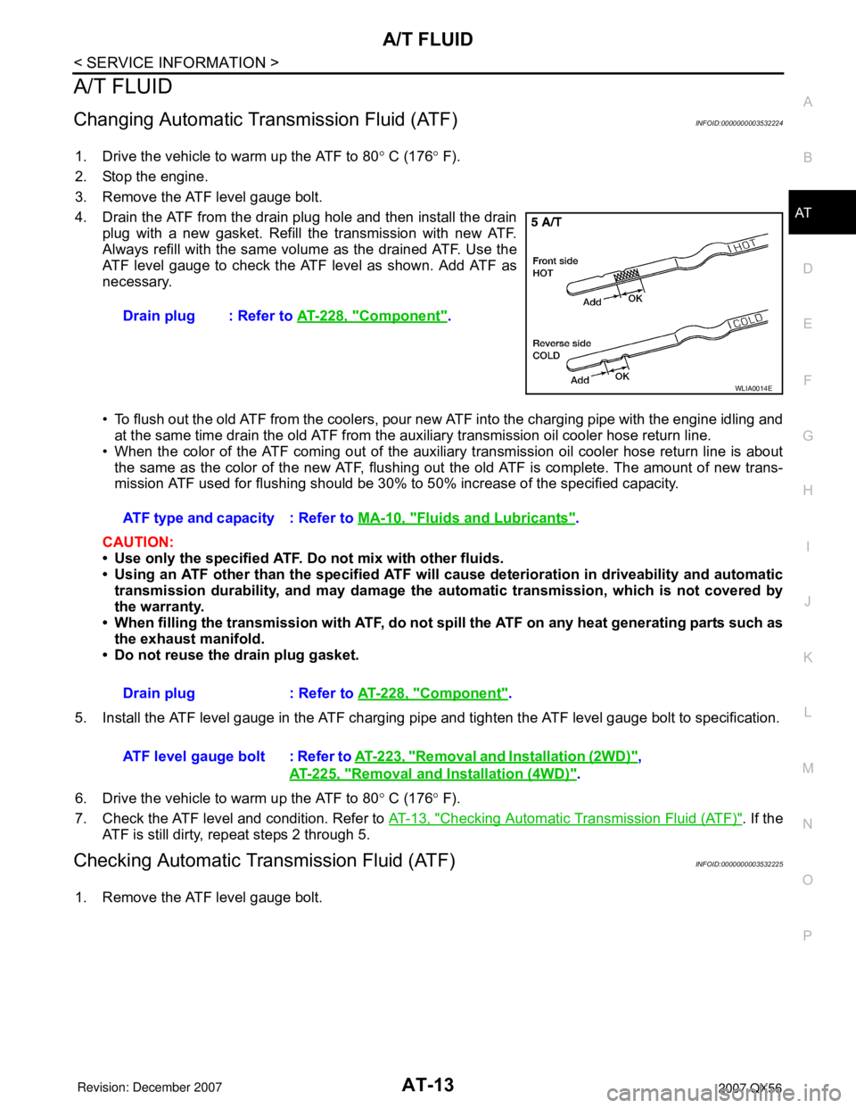
4. Drain the ATF from the drain plug hole and then install the drain
plug with a new gasket. Refill the transmission with new ATF.
Always refill with the same volume as the drained ATF. Use the
ATF level gauge to check the ATF level as shown. Add ATF as
necessary.
• To flush out the old ATF from the coolers, pour new ATF into the charging pipe with the engine idling and
at the same time drain the old ATF from the auxiliary transmission oil cooler hose return line.
• When the color of the ATF coming out of the auxiliary transmission oil cooler hose return line is about
the same as the color of the new ATF, flushing out the old ATF is complete. The amount of new trans-
mission ATF used for flushing should be 30% to 50% increase of the specified capacity.
CAUTION:
• Use only the specified ATF. Do not mix with other fluids.
• Using an ATF other than the specified ATF will cause deterioration in driveability and automatic
transmission durability, and may damage the automatic transmission, which is not covered by
the warranty.
• When filling the transmission with ATF, do not spill the ATF on any heat generating parts such as
the exhaust manifold.
• Do not reuse the drain plug gasket.
5. Install the ATF level gauge in the ATF charging pipe and tighten the ATF level gauge bolt to specification.
6. Drive the vehicle to warm up the ATF to 80° C (176° F).
7. Check the ATF level and condition. Refer to AT-13, "
Checking Automatic Transmission Fluid (ATF)". If the
ATF is still dirty, repeat steps 2 through 5.
Checking Automatic Transmission Fluid (ATF)INFOID:0000000003532225
1. Remove the ATF level gauge bolt.Drain plug : Refer to AT-228, "
Component".
WLIA0014E
ATF type and capacity : Refer to MA-10, "Fluids and Lubricants".
Drain plug : Refer to AT-228, "
Component".
ATF level gauge bolt : Refer to AT-223, "
Removal and Installation (2WD)",
AT-225, "
Removal and Installation (4WD)".
Page 368 of 3061

AT-298
< SERVICE INFORMATION >
SERVICE DATA AND SPECIFICATIONS (SDS)
SERVICE DATA AND SPECIFICATIONS (SDS)
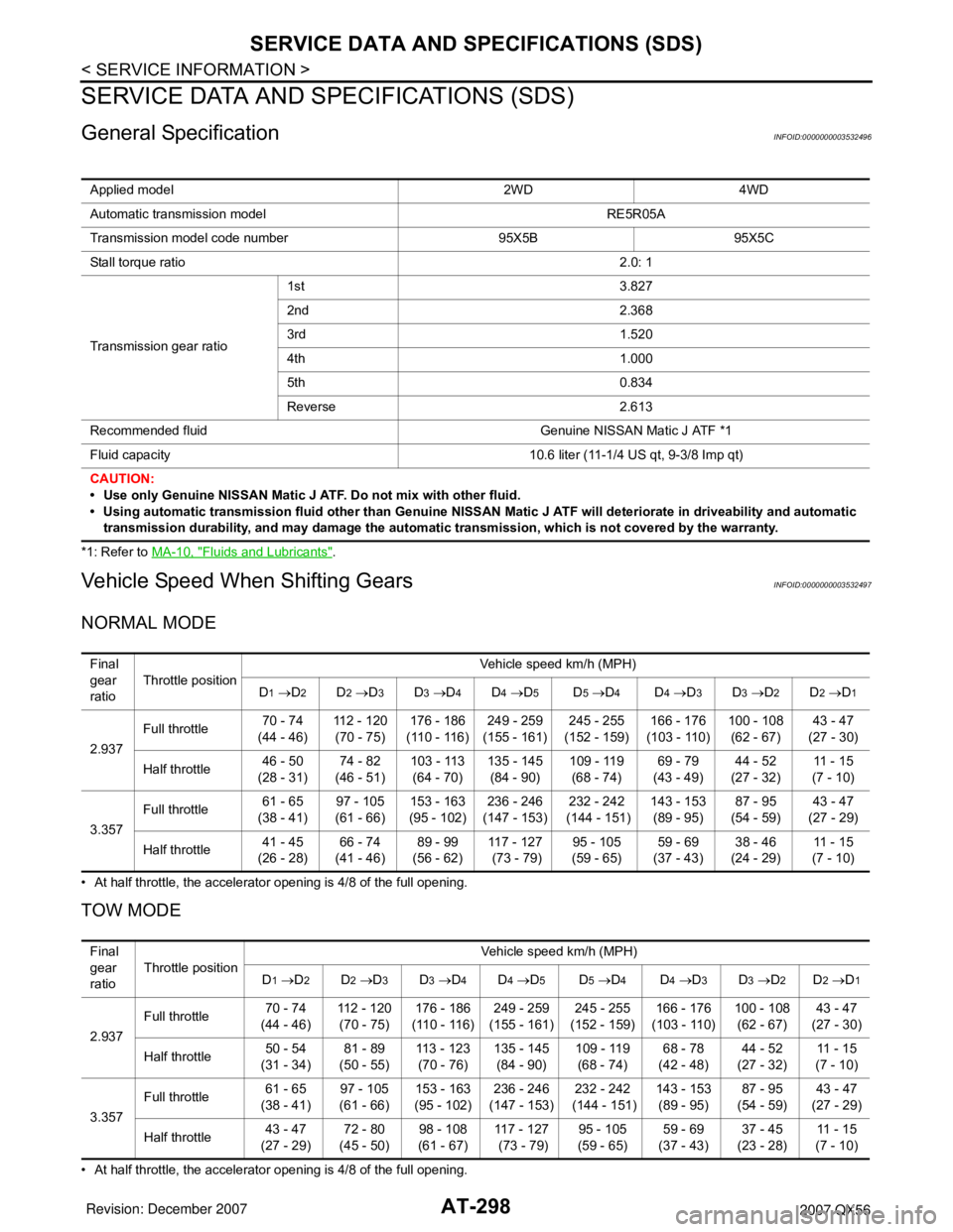
General SpecificationINFOID:0000000003532496
*1: Refer to MA-10, "Fluids and Lubricants".
Vehicle Speed When Shifting GearsINFOID:0000000003532497
NORMAL MODE
• At half throttle, the accelerator opening is 4/8 of the full opening.
TOW MODE
• At half throttle, the accelerator opening is 4/8 of the full opening.Applied model 2WD 4WD
Automatic transmission model RE5R05A
Transmission model code number 95X5B 95X5C
Stall torque ratio2.0: 1
Transmission gear ratio1st 3.827
2nd 2.368
3rd 1.520
4th 1.000
5th 0.834
Reverse 2.613
Recommended fluid Genuine NISSAN Matic J ATF *1
Fluid capacity 10.6 liter (11-1/4 US qt, 9-3/8 Imp qt)
CAUTION:
• Use only Genuine NISSAN Matic J ATF. Do not mix with other fluid.
• Using automatic transmission fluid other than Genuine NISSAN Matic J ATF will deteriorate in driveability and automatic
transmission durability, and may damage the automatic transmission, which is not covered by the warranty.
Final
gear
ratioThrottle positionVehicle speed km/h (MPH)
D
1 →D2D2 →D3D3 →D4D4 →D5D5 →D4D4 →D3D3 →D2D2 →D1
2.937Full throttle 70 - 74
(44 - 46)112 - 120
(70 - 75)176 - 186
(110 - 116)249 - 259
(155 - 161)245 - 255
(152 - 159)166 - 176
(103 - 110)100 - 108
(62 - 67)43 - 47
(27 - 30)
Half throttle 46 - 50
(28 - 31)74 - 82
(46 - 51)103 - 113
(64 - 70)135 - 145
(84 - 90)109 - 119
(68 - 74)69 - 79
(43 - 49)44 - 52
(27 - 32)11 - 1 5
(7 - 10)
3.357Full throttle 61 - 65
(38 - 41)97 - 105
(61 - 66)153 - 163
(95 - 102)236 - 246
(147 - 153)232 - 242
(144 - 151)143 - 153
(89 - 95)87 - 95
(54 - 59)43 - 47
(27 - 29)
Half throttle 41 - 45
(26 - 28)66 - 74
(41 - 46)89 - 99
(56 - 62)117 - 127
(73 - 79)95 - 105
(59 - 65)59 - 69
(37 - 43)38 - 46
(24 - 29)11 - 1 5
(7 - 10)
Final
gear
ratioThrottle positionVehicle speed km/h (MPH)
D
1 →D2D2 →D3D3 →D4D4 →D5D5 →D4D4 →D3D3 →D2D2 →D1
2.937Full throttle 70 - 74
(44 - 46)112 - 120
(70 - 75)176 - 186
(110 - 116)249 - 259
(155 - 161)245 - 255
(152 - 159)166 - 176
(103 - 110)100 - 108
(62 - 67)43 - 47
(27 - 30)
Half throttle 50 - 54
(31 - 34)81 - 89
(50 - 55)113 - 123
(70 - 76)135 - 145
(84 - 90)109 - 119
(68 - 74)68 - 78
(42 - 48)44 - 52
(27 - 32)11 - 1 5
(7 - 10)
3.357Full throttle 61 - 65
(38 - 41)97 - 105
(61 - 66)153 - 163
(95 - 102)236 - 246
(147 - 153)232 - 242
(144 - 151)143 - 153
(89 - 95)87 - 95
(54 - 59)43 - 47
(27 - 29)
Half throttle 43 - 47
(27 - 29)72 - 80
(45 - 50)98 - 108
(61 - 67)117 - 127
(73 - 79)95 - 105
(59 - 65)59 - 69
(37 - 43)37 - 45
(23 - 28)11 - 1 5
(7 - 10)
Page 900 of 3061

BR-2
< SERVICE INFORMATION >
PRECAUTIONS
SERVICE INFORMATION
PRECAUTIONS
Precaution for Supplemental Restraint System (SRS) "AIR BAG" and "SEAT BELT
PRE-TENSIONER"
INFOID:0000000003532717
The Supplemental Restraint System such as “AIR BAG” and “SEAT BELT PRE-TENSIONER”, used along
with a front seat belt, helps to reduce the risk or severity of injury to the driver and front passenger for certain
types of collision. This system includes seat belt switch inputs and dual stage front air bag modules. The SRS
system uses the seat belt switches to determine the front air bag deployment, and may only deploy one front
air bag, depending on the severity of a collision and whether the front occupants are belted or unbelted.
Information necessary to service the system safely is included in the SRS and SB section of this Service Man-
ual.
WARNING:
• To avoid rendering the SRS inoperative, which could increase the risk of personal injury or death in
the event of a collision which would result in air bag inflation, all maintenance must be performed by
an authorized NISSAN/INFINITI dealer.
• Improper maintenance, including incorrect removal and installation of the SRS, can lead to personal
injury caused by unintentional activation of the system. For removal of Spiral Cable and Air Bag
Module, see the SRS section.
• Do not use electrical test equipment on any circuit related to the SRS unless instructed to in this
Service Manual. SRS wiring harnesses can be identified by yellow and/or orange harnesses or har-
ness connectors.
Precaution for Brake SystemINFOID:0000000003532718
• Always use recommended brake fluid. Refer to MA-10 .
• Do not reuse drained brake fluid.
• Be careful not to splash brake fluid on painted areas.
• To clean or wash all parts of master cylinder, disc brake caliper and wheel cylinder, use clean brake fluid.
• Do not use mineral oils such as gasoline or kerosene. They will ruin rubber parts of the hydraulic system.
• Use flare nut wrench when removing and installing brake tube.
• Always check tightening torque when installing brake lines.
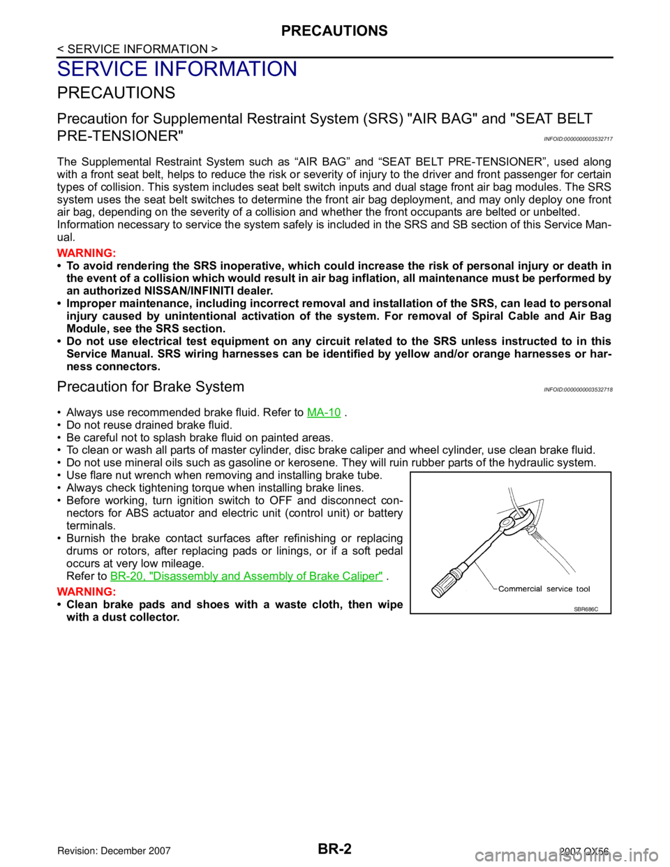
• Before working, turn ignition switch to OFF and disconnect con-
nectors for ABS actuator and electric unit (control unit) or battery
terminals.
• Burnish the brake contact surfaces after refinishing or replacing
drums or rotors, after replacing pads or linings, or if a soft pedal
occurs at very low mileage.
Refer to BR-20, "
Disassembly and Assembly of Brake Caliper" .
WARNING:
• Clean brake pads and shoes with a waste cloth, then wipe
with a dust collector.
SBR686C
Page 906 of 3061

BR-8
< SERVICE INFORMATION >
BRAKE FLUID
BRAKE FLUID
On Board InspectionINFOID:0000000003532724
LEVEL CHECK
• Make sure the fluid level in reservoir tank is within the standard
(between MAX and MIN lines).
• Visually check around reservoir tank for fluid leaks.
• If fluid level is excessively low, check brake system for leaks.
• If brake warning lamp remains illuminated after parking lever is
released, check brake system for fluid leakage.
Drain and RefillINFOID:0000000003532725
CAUTION:
• Refill with new brake fluid. Refer to MA-10
.
• Do not reuse drained brake fluid.
• Do not let brake fluid splash on the painted surfaces of the body. This might damage the paint, so
when splashing it, immediately wipe off the area and wash away with water.
• Before servicing, disconnect actuator connector or battery negative cable.
1. Connect a vinyl tube to each bleed valve.
2. Depress brake pedal, loosen each bleed valve, and gradually
remove brake fluid.
3. Make sure there is no foreign material in reservoir tank, and refill
with new brake fluid.
4. Rest foot on brake pedal. Loosen bleed valve. Slowly depress
pedal until it stops. Tighten bleed valve. Release brake pedal.
Repeat this process a few times, then pause to add new brake
fluid to master cylinder. Continue until new brake fluid flows out.
Bleed air from brake system. Refer to BR-8, "
Bleeding Brake
System" .
Bleeding Brake SystemINFOID:0000000003532726
CAUTION:
While bleeding, pay attention to master cylinder fluid level.
1. Turn ignition switch OFF and disconnect ABS actuator and electric unit (control unit) connector or battery
negative cable.
2. Connect a vinyl tube to the rear right bleed valve.
3. Fully depress brake pedal 4 to 5 times.
LFIA0225E
SBR419C
SBR995
Page 908 of 3061

BR-10
< SERVICE INFORMATION >
BRAKE PIPING AND HOSE
BRAKE PIPING AND HOSE
Hydraulic CircuitINFOID:0000000003532727
CAUTION:
• All hoses and tubes must be free from excessive bending, twisting and pulling.
• Make sure there is no interference with other parts when turning steering both clockwise and coun-
terclockwise.
• The brake piping is an important safety part. If a brake fluid leak is detected, always disassemble the
parts. Replace applicable part with a new one, if necessary.
• Be careful not to splash brake fluid on painted areas; it way cause paint damage. If brake fluid is
splashed on painted areas, wash it away with water immediately.
• Do not bend or twist brake hose sharply, or strongly pull it.
• When removing components, cover connections so that no dirt, dust, or other foreign matter gets in.
• Refill with new brake fluid. Refer to MA-10
.
• Do not reuse drained brake fluid.
Removal and Installation of Front Brake HoseINFOID:0000000003532728
REMOVAL
1. Drain brake fluid. Refer to BR-8, "Drain and Refill" .
2. Using a flare nut wrench, remove brake tube from brake hose.
3. Remove lock plate and brake hose from bracket.
4. Remove union bolt and then remove brake hose from cylinder body.
INSTALLATION
1. Actuator 2. Master cylinder 3. Brake booster
4. Connector
WFIA0278E
Page 912 of 3061

BR-14
< SERVICE INFORMATION >
BRAKE MASTER CYLINDER
• Refill brake fluid and bleed air. Refer to BR-8, "Bleeding Brake System".
CAUTION:
• Refill with new brake fluid. Refer to MA-10
.
• Do not reuse drained brake fluid.
• Adjust brake pedal. Refer to BR-5, "
Inspection and Adjustment" .
Disassembly and AssemblyINFOID:0000000003532733
DISASSEMBLY
CAUTION:
• Master cylinder cannot be disassembled.
• Remove reservoir tank only when absolutely necessary.
Pull reservoir tank off master cylinder sub-assembly, then remove grommets from master cylinder sub-assem-
bly body.
ASSEMBLY
CAUTION:
• Never use mineral oil such as kerosene, gasoline during the cleaning and assembly process.
• Do not drop parts. If a part is dropped, do not use it.
1. Apply brake fluid or rubber grease to new grommets, then insert into master cylinder sub-assembly. Refer
to GI-45
.
CAUTION:
Do not reuse grommet.
2. Install reservoir tank onto master cylinder sub-assembly.
Page 918 of 3061

BR-20
< SERVICE INFORMATION >
FRONT DISC BRAKE
4. Remove disc rotor.
INSTALLATION
CAUTION:
• Refill with new brake fluid. Refer to MA-10
.
• Do not reuse drained brake fluid.
1. Install disc rotor.
2. Install sliding pin bolts and torque member to caliper, if removed. Refer to BR-18, "
Component" .
3. Install caliper assembly to the vehicle, then tighten the torque
member bolts to the specified torque. Refer to BR-18, "
Compo-
nent" .
CAUTION:
• When attaching caliper assembly to the vehicle, wipe any
oil off knuckle spindle, washers and caliper assembly
attachment surfaces.
• Do not reuse caliper torque member bolts.
4. Install brake hose to cylinder body, then tighten union bolt to
specification, as necessary. Refer to BR-18, "
Component" .
CAUTION:
• Do not reuse copper washer.
• Install brake hose to caliper assembly together with union
bolt and washers.
5. Refill with new brake fluid and bleed air. Refer to BR-8, "
Bleeding Brake System" .
6. Install tires to the vehicle. Refer to WT-7, "
Rotation" .
Disassembly and Assembly of Brake CaliperINFOID:0000000003532742
DISASSEMBLY
1. Remove sliding pin bolt, and then remove the pad, shim, shim cover, and pad retainer from the torque
member.
2. Remove sliding pins and sliding pin boots from torque member.
3. Place a wooden block as shown, and blow air from union bolt
mounting hole to remove pistons and piston boots.
CAUTION:
Keep hands away from piston.
LFIA0209E
LFIA0214E
BRB0032D
Page 923 of 3061

REAR DISC BRAKE
BR-25
< SERVICE INFORMATION >
C
D
E
G
H
I
J
K
L
MA
B
BR
N
O
P
WARNING:
Clean dust on caliper and brake pad with a vacuum dust collector to minimize the hazard of airborne
particles or other materials.
CAUTION:
• While removing cylinder body, never depress brake pedal because piston will pop out.
• It is not necessary to remove bolts on torque member and brake hose except for disassembly or
replacement of cylinder body. In this case, hang cylinder body with a wire so as not to stretch brake
hose.
• Do not damage piston boot.
• Burnish brake contact surface after refinishing or replacing rotors, after replacing pads, or it a soft
pedal occurs at very low mileage. Refer to BR-26, "
Brake Caliper" .
Removal and Installation of Brake PadINFOID:0000000003532745
REMOVAL
1. Remove tires from vehicle with power tool.
2. Remove the top bolt from the cylinder body.
3. Swing cylinder body open, and remove pads.
INSTALLATION
1. Push piston in so that pad is firmly attached and install cylinder body to torque member.
NOTE:
Using a disc brake piston tool (commercial service tool), makes it easier to push in the piston.
CAUTION:
By pushing in piston, brake fluid returns to master cylinder reservoir tank. Watch the level of the
surface of reservoir tank.
2. Apply Molykote M-77 grease to knuckle slide where brake pad contacts.
CAUTION:
Do not get grease on the brake rotor friction surface.
3. Install pads to cylinder body.
4. Install cylinder body top bolt and tighten to specification.
5. Check brake for drag.
6. Install tires to the vehicle. Refer to WT-7, "
Rotation" .
Removal and Installation of Brake Caliper and Disc RotorINFOID:0000000003532746
REMOVAL
1. Remove tires from vehicle with power tool.
2. Drain brake fluid as necessary. Refer to BR-8, "
Drain and Refill" .
NOTE:
Do not remove union bolt unless removing cylinder body from vehicle.
3. Remove mounting bolts and cylinder body.
NOTE:
Position cylinder body aside using suitable wire, as necessary.
4. Remove disc rotor.
INSTALLATION
CAUTION:
• Refill with new brake fluid. Refer to MA-10
.
• Do not reuse drained brake fluid.
1. Install disc rotor.
LFIA0211E
Page 924 of 3061

BR-26
< SERVICE INFORMATION >
REAR DISC BRAKE
2. Install cylinder body and tighten bolts to specification. Refer to BR-24, "Exploded View" .
CAUTION:
Before installing cylinder body to the vehicle, wipe off mating surface of cylinder body.
3. Install brake hose to cylinder body and tighten union bolt to specification as necessary. Refer to BR-24,
"Exploded View".
CAUTION:
• Do not reuse copper washers.
• Securely attach brake hose to protrusion on cylinder body.
4. Refill new brake fluid and bleed air as necessary. Refer to BR-8, "
Bleeding Brake System" .
5. Install tires to the vehicle. Refer to WT-7, "
Rotation" .
Brake CaliperINFOID:0000000003532747
DISASSEMBLY
1. Remove pads from cylinder body.
2. Remove sliding sleeve and boot from cylinder body.
3. Place a wooden block as shown, and blow air into union bolt
hole to remove piston and piston boot.
CAUTION:
Do not get your fingers caught in piston.
4. Using a suitable tool, remove piston seal from cylinder body as
shown.
CAUTION:
Be careful not to damage cylinder body inner wall.
CALIPER INSPECTION
Cylinder Body
CAUTION:
• Use new brake fluid to clean. Do not use mineral oils such as gasoline or kerosene. Refer to MA-10
.
• Check inside surface of cylinder body for score, rust wear, damage or foreign materials. If any of the
above conditions are observed, replace cylinder body.
• Minor damage from rust or foreign materials may be eliminated by polishing surface with a fine
emery paper. Replace cylinder body if necessary.
Torque Member
Check for wear, cracks, and damage. If damage or deformation is present, replace the affected part.
Piston
CAUTION:
• Piston sliding surface is plated, do not polish with emery paper even if rust of foreign materials are
stuck to sliding surface.
• Check piston for score, rust, wear, damage or presence of foreign materials. Replace if any of the
above conditions are observed.
Sliding Pin Bolts and Sliding Pin Boots
BRD0041D
PFIA0269E