MA-10 INFINITI QX56 2007 Factory Owner's Manual
[x] Cancel search | Manufacturer: INFINITI, Model Year: 2007, Model line: QX56, Model: INFINITI QX56 2007Pages: 3061, PDF Size: 64.56 MB
Page 1897 of 3061
DRIVE SHAFT
FAX-11
< SERVICE INFORMATION >
C
E
F
G
H
I
J
K
L
MA
B
FA X
N
O
P
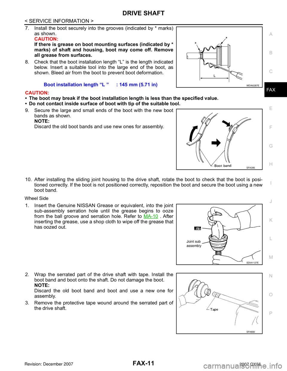
7. Install the boot securely into the grooves (indicated by * marks)
as shown.
CAUTION:
If there is grease on boot mounting surfaces (indicated by *
marks) of shaft and housing, boot may come off. Remove
all grease from surfaces.
8. Check that the boot installation length “L” is the length indicated
below. Insert a suitable tool into the large end of the boot, as
shown. Bleed air from the boot to prevent boot deformation.
CAUTION:
• The boot may break if the boot installation length is less than the specified value.
• Do not contact inside surface of boot with tip of the suitable tool.
9. Secure the large and small ends of the boot with the new boot
bands as shown.
NOTE:
Discard the old boot bands and use new ones for assembly.
10. After installing the sliding joint housing to the drive shaft, rotate the boot to check that the boot is posi-
tioned correctly. If the boot is not positioned correctly, reposition the boot and secure the boot using a new
boot band.
Wheel Side
1. Insert the Genuine NISSAN Grease or equivalent, into the joint
sub-assembly serration hole until the grease begins to ooze
from the ball groove and serration hole. Refer to MA-10
. After
inserting the grease, use a shop cloth to wipe off the grease that
has oozed out.
2. Wrap the serrated part of the drive shaft with tape. Install the
boot band and boot onto the shaft. Do not damage the boot.
NOTE:
Discard the old boot band and boot and use a new one for
assembly.
3. Remove the protective tape wound around the serrated part of
the drive shaft.Boot installation length “L ” : 145 mm (5.71 in)
WDIA0287E
SFA395
SDIA1127E
SFA800
Page 1898 of 3061
FAX-12
< SERVICE INFORMATION >
DRIVE SHAFT
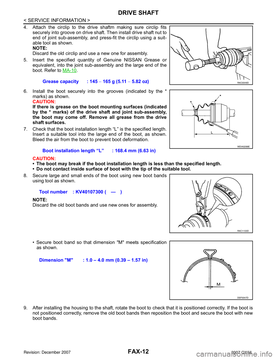
4. Attach the circlip to the drive shaftm making sure circlip fits
securely into groove on drive shaft. Then install drive shaft nut to
end of joint sub-assembly, and press-fit the circlip using a suit-
able tool as shown.
NOTE:
Discard the old circlip and use a new one for assembly.
5. Insert the specified quantity of Genuine NISSAN Grease or
equivalent, into the joint sub-assembly and the large end of the
boot. Refer to MA-10
.
6. Install the boot securely into the grooves (indicated by the *
marks) as shown.
CAUTION:
If there is grease on the boot mounting surfaces (indicated
by the * marks) of the drive shaft and joint sub-assembly,
the boot may come off. Remove all grease from the drive
shaft surfaces.
7. Check that the boot installation length “L” is the specified length.
Insert a suitable tool into the large end of the boot, as shown.
Bleed the air from the boot to prevent boot deformation.
CAUTION:
• The boot may break if the boot installation length is less than the specified length.
• Do not contact inside surface of boot with the tip of the suitable tool.
8. Secure large and small ends of the boot using new boot bands
using tool as shown.
NOTE:
Discard the old boot bands and use new ones for assembly.
• Secure boot band so that dimension "M" meets specification
as shown.
9. After installing the housing to the shaft, rotate the boot to check that it is positioned correctly. If the boot is
not positioned correctly, remove the old boot bands then reposition the boot and secure the boot with new
boot bands.Grease capacity : 145 − 165 g (5.11 − 5.82 oz)
RAC0049D
Boot installation length “L” : 168.4 mm (6.63 in)
Tool number : KV40107300 ( — )
WDIA0288E
RAC1133D
Dimension "M" : 1.0 – 4.0 mm (0.39 – 1.57 in)
DSF0047D
Page 1906 of 3061
DIFFERENTIAL GEAR OIL
FFD-7
< SERVICE INFORMATION >
C
E
F
G
H
I
J
K
L
MA
B
FFD
N
O
P
DIFFERENTIAL GEAR OIL
Changing Differential Gear OilINFOID:0000000003532588
DRAINING
1. Stop the engine.
2. Remove the drain plug from the front final drive assembly to drain the differential gear oil.
3. Install the drain plug with sealant applied on the threads to the front final drive assembly. Tighten to the
specified torque. Refer to FFD-13, "
Disassembly and Assembly".
• Use High Performance Thread Sealant or equivalent. Refer to GI-45, "
Recommended Chemical Product
and Sealant".
FILLING
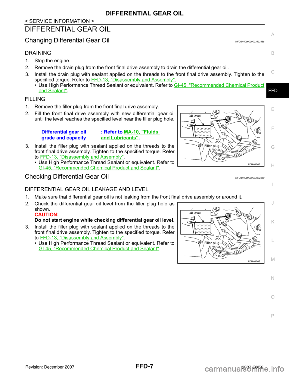
1. Remove the filler plug from the front final drive assembly.
2. Fill the front final drive assembly with new differential gear oil
until the level reaches the specified level near the filler plug hole.
3. Install the filler plug with sealant applied on the threads to the
front final drive assembly. Tighten to the specified torque. Refer
to FFD-13, "
Disassembly and Assembly".
• Use High Performance Thread Sealant or equivalent. Refer to
GI-45, "
Recommended Chemical Product and Sealant".
Checking Differential Gear OilINFOID:0000000003532589
DIFFERENTIAL GEAR OIL LEAKAGE AND LEVEL
1. Make sure that differential gear oil is not leaking from the front final drive assembly or around it.
2. Check the differential gear oil level from the filler plug hole as
shown.
CAUTION:
Do not start engine while checking differential gear oil level.
3. Install the filler plug with sealant applied on the threads to the
front final drive assembly. Tighten to the specified torque. Refer
to FFD-13, "
Disassembly and Assembly".
• Use High Performance Thread Sealant or equivalent. Refer to
GI-45, "
Recommended Chemical Product and Sealant". Differential gear oil
grade and capacity: Refer to MA-10, "
Fluids
and Lubricants".
LDIA0176E
LDIA0176E
Page 2107 of 3061
IDX-3
A
C
D
E
F
G
H
I
J
K
L B
IDX
ALPHABETICAL INDEX
Brake fluid level ................................................. MA-28
Brake hydraulic line ........................................... BR-12
Brake inspection ................................................ MA-28
Brake lines and cables inspection ..................... MA-28
Brake master cylinder ....................................... BR-15
Brake switch ...................................... EC-572, EC-584
BRK/SW - Wiring diagram ............................... EC-585
Bulb specifications ........................................... LT-148
Bumper, front ...................................................... EI-13
Bumper, rear ....................................................... EI-15
C
Cabin air filter .................................................... MA-21
Camshaft ........................................................... EM-46
Camshaft inspection .......................................... EM-49
Camshaft position sensor (PHASE) ................ EC-369
CAN - Wiring diagram .............. EC-157, AT-93, AT-94
CAN communication EC-32, EC-156, EC-159, TF-112,
RSU-6
Canister-See EVAP canister ............................. EC-36
Center case (Transfer) ....................... TF-154, TF-167
CHARGE - Wiring diagram ............................... SC-19
Charging system ............................................... SC-17
Chassis and body maintenance ........................ MA-21
Chassis and body maintenanceSchedule 1 ........ MA-8
Chassis and body maintenanceSchedule 2 ...... MA-10
CHIME - Wiring diagram ..................................... DI-41
Circuit breaker ................................................... PG-17
Clock ................................................................... DI-61
CLOCK - Wiring diagram .................................... DI-61
Closed loop control ............................. EC-26, EC-501
Closed loop control (Bank 1) ........................... EC-501
Closed loop control (Bank 2) ........................... EC-501
Clutch drum (Transfer) ....................... TF-154, TF-167
Clutch pressure switch (Transfer) ...... TF-154, TF-167
Coil spring (front) ............................................. FSU-10
Collision diagnosis .......................................... SRS-53
Combination lamp, front, removal and installation . LT-
25
Combination lamp, rear, removal and installation .. LT-
101
Combination meter ................................................ DI-5
Combination switch ............................................ LT-79
COMBSW - Wiring diagram ............................... LT-79
COMM - Wiring diagram ................................... AV-94
COMPAS - Wiring diagram ................................. DI-24
Compass ............................................................. DI-23
Component Location (auto A/C) ...................... ATC-38
Compressor clutch removal and installation . ATC-180
Compressor mounting ................................... ATC-179
Compressor precaution ................................... ATC-11
Compressor special service tool ..................... ATC-14
Condenser ..................................................... ATC-184
Connecting rod .................................................. EM-96
Connecting rod bearing clearance .................... EM-96
Connecting rod bushing clearance .................... EM-96
Console box - See Instrument panel ................... IP-10
CONSULT for VDC ......................................... BRC-27
CONSULT general information ........................... GI-37
CONSULT-II for engine ................................... EC-118
Control units (terminal arrangement) ................. PG-71
Control valve (A/T) ............................................. AT-36
Control valve (Transfer) ...................... TF-154, TF-167
Converter housing installation ............ AT-240, AT-244
COOL/F - Wiring diagram ................................ EC-507
Coolant mixture ratio ......................................... MA-12
Coolant replacement ............................ CO-10, MA-13
Cooling circuit (engine) ........................................ CO-8
Cooling fan ........................................................ CO-17
Cooling fan control ........................................... EC-504
Cooling fan motor ............................................ EC-513
Cooling unit (A/C evaporator) ....... ATC-157, ATC-186
Corrosion protection ......................................... BL-157
Crankcase ventilation system - See Positive crankcase
ventilation .......................................................... EC-46
Crankshaft ......................................................... EM-79
Crankshaft position sensor (POS) ................... EC-362
Crash zone sensor .......................................... SRS-48
CUR/SE - Wiring diagram ... EC-522, EC-529, EC-536,
EC-543
Cylinder block .................................................... EM-78
Cylinder block boring ......................................... EM-99
D
D/LOCK - Wiring diagram ................................... BL-19
Data link connector for Consult ......... EC-120, EC-132
Daytime light system .......................................... LT-27
Daytime running light - See Daytime light system .. LT-
27
DEF - Wiring diagram ....................................... GW-74
Diagnosis sensor unit ...................................... SRS-51
Diagnostic trouble code (DTC) for OBD system . EC-9,
EC-54
Diagnostic trouble code (DTC) inspection priority chart
EC-91
Differential carrier assembly ............................ RFD-15
Differential gear oil replacement ........................ MA-26
Dimensions ......................................................... GI-51
Direct clutch solenoid valve ................ AT-143, AT-145
Display and amp.assembly .............................. ATC-59
Display Control Unit ........................................... AV-83
Display Unit ....................................................... AV-83
Dome light - See Interior lamp .......................... LT-110
Door glass .......................................... GW-62, GW-65
Door lock .......................................................... BL-121
Door mirror lamp ............................................... LT-110
Door trim .............................................................. EI-32
Door, front ........................................... BL-117, GW-62
Door, rear ........................................... BL-117, GW-65
Drive belt ........................................................... EM-13
Drive chain (Transfer) ......................... TF-149, TF-176
Drive pinion diff. inspection .............................. RFD-18
Drive shaft (rear) ................................................ RAX-7
Driver air bag ................................................... SRS-39
DTC work support ............................................ EC-128
DTRL - Wiring diagram ....................................... LT-31
Page 2354 of 3061
ENGINE OIL
LU-9
< SERVICE INFORMATION >
C
D
E
F
G
H
I
J
K
L
MA
LU
N
P O
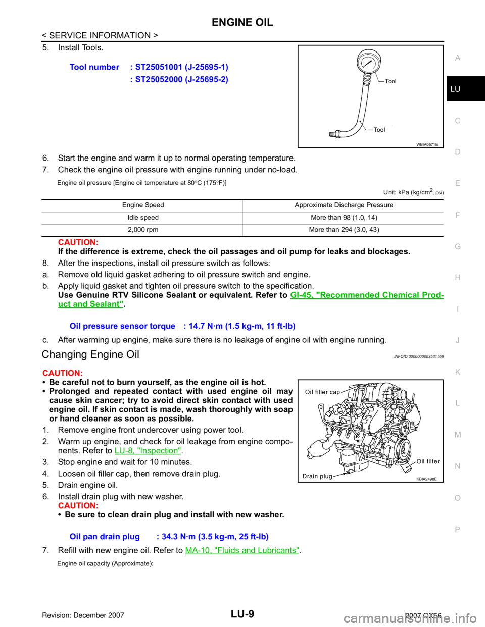
5. Install Tools.
6. Start the engine and warm it up to normal operating temperature.
7. Check the engine oil pressure with engine running under no-load.
Engine oil pressure [Engine oil temperature at 80°C (175°F)]
Unit: kPa (kg/cm2
, psi)
CAUTION:
If the difference is extreme, check the oil passages and oil pump for leaks and blockages.
8. After the inspections, install oil pressure switch as follows:
a. Remove old liquid gasket adhering to oil pressure switch and engine.
b. Apply liquid gasket and tighten oil pressure switch to the specification.
Use Genuine RTV Silicone Sealant or equivalent. Refer to GI-45, "
Recommended Chemical Prod-
uct and Sealant".
c. After warming up engine, make sure there is no leakage of engine oil with engine running.
Changing Engine OilINFOID:0000000003531556
CAUTION:
• Be careful not to burn yourself, as the engine oil is hot.
• Prolonged and repeated contact with used engine oil may
cause skin cancer; try to avoid direct skin contact with used
engine oil. If skin contact is made, wash thoroughly with soap
or hand cleaner as soon as possible.
1. Remove engine front undercover using power tool.
2. Warm up engine, and check for oil leakage from engine compo-
nents. Refer to LU-8, "
Inspection".
3. Stop engine and wait for 10 minutes.
4. Loosen oil filler cap, then remove drain plug.
5. Drain engine oil.
6. Install drain plug with new washer.
CAUTION:
• Be sure to clean drain plug and install with new washer.
7. Refill with new engine oil. Refer to MA-10, "
Fluids and Lubricants".
Engine oil capacity (Approximate):
Tool number : ST25051001 (J-25695-1)
: ST25052000 (J-25695-2)
WBIA0571E
Engine Speed Approximate Discharge Pressure
Idle speed More than 98 (1.0, 14)
2,000 rpm More than 294 (3.0, 43)
Oil pressure sensor torque : 14.7 N·m (1.5 kg-m, 11 ft-lb)
Oil pan drain plug : 34.3 N·m (3.5 kg-m, 25 ft-lb)
KBIA2498E
Page 2372 of 3061
MA-10
< SERVICE INFORMATION >
RECOMMENDED FLUIDS AND LUBRICANTS
RECOMMENDED FLUIDS AND LUBRICANTS
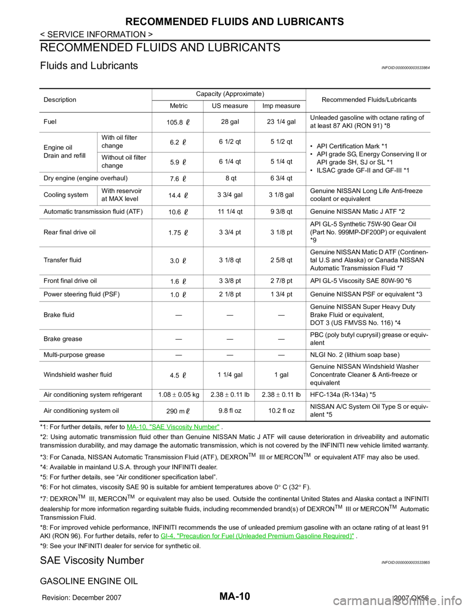
Fluids and LubricantsINFOID:0000000003533864
*1: For further details, refer to MA-10, "SAE Viscosity Number" .
*2: Using automatic transmission fluid other than Genuine NISSAN Matic J ATF will cause deterioration in driveability and automatic
transmission durability, and may damage the automatic transmission, which is not covered by the INFINITI new vehicle limited warranty.
*3: For Canada, NISSAN Automatic Transmission Fluid (ATF), DEXRON
TM III or MERCONTM or equivalent ATF may also be used.
*4: Available in mainland U.S.A. through your INFINITI dealer.
*5: For further details, see “Air conditioner specification label”.
*6: For hot climates, viscosity SAE 90 is suitable for ambient temperatures above 0° C (32° F).
*7: DEXRON
TM III, MERCONTM or equivalent may also be used. Outside the continental United States and Alaska contact a INFINITI
dealership for more information regarding suitable fluids, including recommended brand(s) of DEXRONTM III or MERCONTM Automatic
Transmission Fluid.
*8: For improved vehicle performance, INFINITI recommends the use of unleaded premium gasoline with an octane rating of at least 91
AKI (RON 96). For further details, refer to GI-4, "
Precaution for Fuel (Unleaded Premium Gasoline Required)" .
*9: See your INFINITI dealer for service for synthetic oil.
SAE Viscosity NumberINFOID:0000000003533865
GASOLINE ENGINE OIL
DescriptionCapacity (Approximate)
Recommended Fluids/Lubricants
Metric US measure Imp measure
Fuel
105.8 28 gal 23 1/4 galUnleaded gasoline with octane rating of
at least 87 AKI (RON 91) *8
Engine oil
Drain and refillWith oil filter
change6.2 6 1/2 qt 5 1/2 qt
• API Certification Mark *1
• API grade SG, Energy Conserving II or
API grade SH, SJ or SL *1
• ILSAC grade GF-II and GF-III *1 Without oil filter
change5.9 6 1/4 qt 5 1/4 qt
Dry engine (engine overhaul)
7.6 8 qt 6 3/4 qt
Cooling systemWith reservoir
at MAX level14.4 3 3/4 gal 3 1/8 galGenuine NISSAN Long Life Anti-freeze
coolant or equivalent
Automatic transmission fluid (ATF)
10.6 11 1/4 qt 9 3/8 qt Genuine NISSAN Matic J ATF *2
Rear final drive oil
1.75 3 3/4 pt 3 1/8 ptAPI GL-5 Synthetic 75W-90 Gear Oil
(Part No. 999MP-DF200P) or equivalent
*9
Transfer fluid
3.0 3 1/8 qt 2 5/8 qtGenuine NISSAN Matic D ATF (Continen-
tal U.S and Alaska) or Canada NISSAN
Automatic Transmission Fluid *7
Front final drive oil
1.6 3 3/8 pt 2 7/8 pt API GL-5 Viscosity SAE 80W-90 *6
Power steering fluid (PSF)
1.0 2 1/8 pt 1 3/4 pt Genuine NISSAN PSF or equivalent *3
Brake fluid — — —Genuine NISSAN Super Heavy Duty
Brake Fluid or equivalent,
DOT 3 (US FMVSS No. 116) *4
Brake grease — — —PBC (poly butyl cuprysil) grease or equiv-
alent
Multi-purpose grease — — — NLGI No. 2 (lithium soap base)
Windshield washer fluid
4.5 1 1/4 gal 1 galGenuine NISSAN Windshield Washer
Concentrate Cleaner & Anti-freeze or
equivalent
Air conditioning system refrigerant 1.08 ± 0.05 kg 2.38 ± 0.11 lb 2.38 ± 0.11 lb HFC-134a (R-134a) *5
Air conditioning system oil
290 m9.8 fl oz 10.2 fl ozNISSAN A/C System Oil Type S or equiv-
alent *5
Page 2376 of 3061
MA-14
< SERVICE INFORMATION >
ENGINE MAINTENANCE
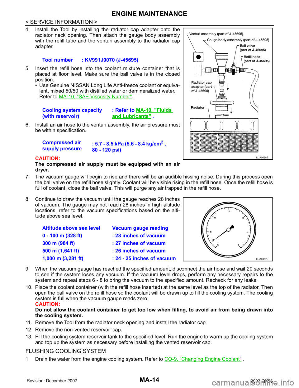
4. Install the Tool by installing the radiator cap adapter onto the
radiator neck opening. Then attach the gauge body assembly
with the refill tube and the venturi assembly to the radiator cap
adapter.
5. Insert the refill hose into the coolant mixture container that is
placed at floor level. Make sure the ball valve is in the closed
position.
• Use Genuine NISSAN Long Life Anti-freeze coolant or equiva-
lent, mixed 50/50 with distilled water or demineralized water.
Refer to MA-10, "
SAE Viscosity Number" .
6. Install an air hose to the venturi assembly, the air pressure must
be within specification.
CAUTION:
The compressed air supply must be equipped with an air
dryer.
7. The vacuum gauge will begin to rise and there will be an audible hissing noise. During this process open
the ball valve on the refill hose slightly. Coolant will be visible rising in the refill hose. Once the refill hose is
full of coolant, close the ball valve. This will purge any air trapped in the refill hose.
8. Continue to draw the vacuum until the gauge reaches 28 inches
of vacuum. The gauge may not reach 28 inches in high altitude
locations, refer to the vacuum specifications based on the alti-
tude above sea level.
9. When the vacuum gauge has reached the specified amount, disconnect the air hose and wait 20 seconds
to see if the system loses any vacuum. If the vacuum level drops, perform any necessary repairs to the
system and repeat steps 6 - 8 to bring the vacuum to the specified amount. Recheck for any leaks.
10. Place the coolant container (with the refill hose inserted) at the same level as the top of the radiator. Then
open the ball valve on the refill hose so the coolant will be drawn up to fill the cooling system. The cooling
system is full when the vacuum gauge reads zero.
CAUTION:
Do not allow the coolant container to get too low when filling, to avoid air from being drawn into
the cooling system.
11. Remove the Tool from the radiator neck opening and install the radiator cap.
12. Remove the non-vented reservoir cap.
13. Fill the cooling system reservoir tank to the specified level. Run the engine to warm up the cooling system
and top up the system as necessary before installing the vented reservoir cap.
FLUSHING COOLING SYSTEM
1. Drain the water from the engine cooling system. Refer to CO-9, "Changing Engine Coolant" . Tool number : KV991J0070 (J-45695)
Cooling system capacity
(with reservoir): Refer to MA-10, "
Fluids
and Lubricants" .
Compressed air
supply pressure: 5.7 - 8.5 kPa (5.6 - 8.4 kg/cm
2 ,
80 - 120 psi)
LLIA0058E
Altitude above sea level Vacuum gauge reading
0 - 100 m (328 ft) : 28 inches of vacuum
300 m (984 ft) : 27 inches of vacuum
500 m (1,641 ft) : 26 inches of vacuum
1,000 m (3,281 ft) : 24 - 25 inches of vacuum
LLIA0057E
Page 2378 of 3061
MA-16
< SERVICE INFORMATION >
ENGINE MAINTENANCE
2. Disconnect the harness connector, then remove the air cleaner case (upper).
3. Remove the air cleaner filter from the air cleaner case (lower).
4. Install the new air cleaner filter in the air cleaner case (lower).
5. Install the air cleaner case (upper) and connect the harness connector.
6. Install the air duct and resonator assembly.
Changing Engine OilINFOID:0000000003533871
WARNING:
• Be careful not to burn yourself, as the engine and engine oil are hot.
• Prolonged and repeated contact with used engine oil may cause skin cancer; try to avoid direct skin
contact with used oil. If skin contact is made, wash thoroughly with soap or hand cleaner as soon as
possible.
1. Warm up the engine, and check for any oil leaks.
2. Stop the engine and wait for at least 10 minutes.
3. Remove the oil drain plug and oil filler cap to drain the old oil.
4. Install a new washer on the oil drain plug, then install the oil drain plug in the oil pan.
CAUTION:
Clean the drain plug and install with a new washer.
5. Refill the engine with new specified engine oil.
CAUTION:
The refill capacity depends on the oil temperature and drain time. Use the “Refill oil capacity” val-
ues as a reference and check the oil level using the dipstick when filling the engine with oil.
6. Warm up the engine and check the area around the drain plug and oil filter for any oil leaks.
7. Stop the engine and wait for more than 10 minutes.
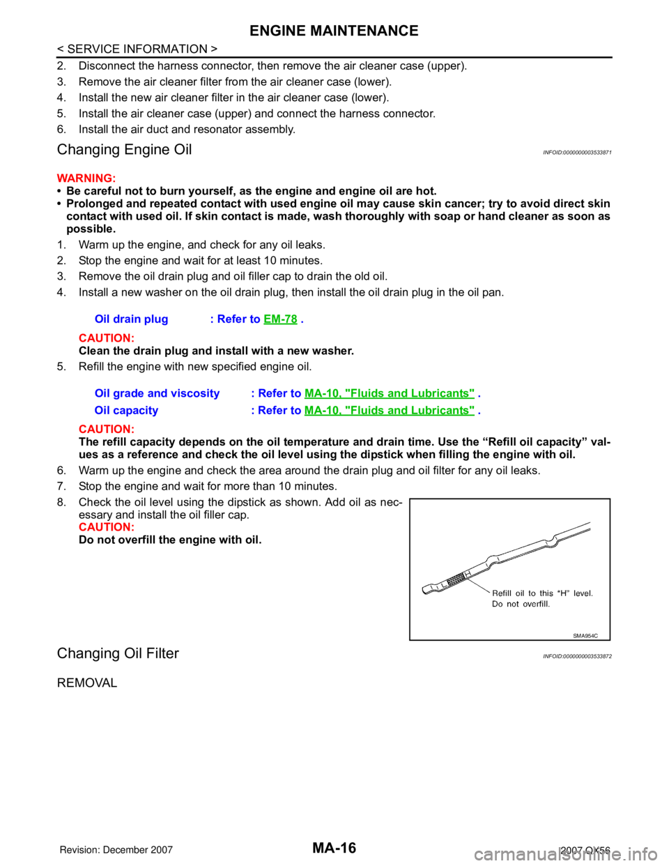
8. Check the oil level using the dipstick as shown. Add oil as nec-
essary and install the oil filler cap.
CAUTION:
Do not overfill the engine with oil.
Changing Oil FilterINFOID:0000000003533872
REMOVAL
Oil drain plug : Refer to EM-78 .
Oil grade and viscosity : Refer to MA-10, "
Fluids and Lubricants" .
Oil capacity : Refer to MA-10, "
Fluids and Lubricants" .
SMA954C
Page 2385 of 3061
CHASSIS AND BODY MAINTENANCE
MA-23
< SERVICE INFORMATION >
C
D
E
F
G
H
I
J
K
MA
B
MA
N
O
P
10. Tighten the level gauge bolt to specification.
Changing Automatic Transmission Fluid (ATF)INFOID:0000000003533878
1. Drive the vehicle to warm up the ATF to 80° C (176° F).
2. Stop the engine.
3. Remove the ATF level gauge bolt.
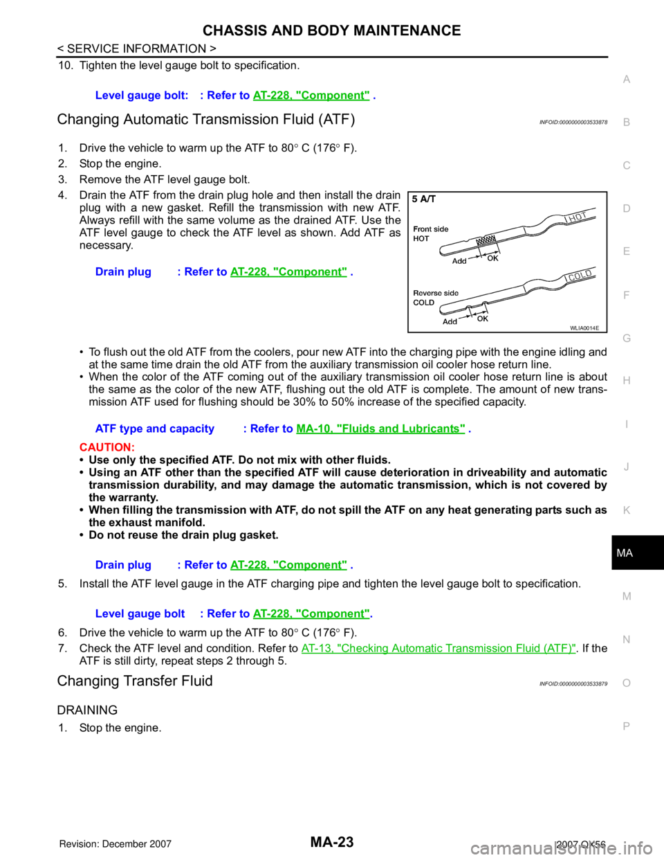
4. Drain the ATF from the drain plug hole and then install the drain
plug with a new gasket. Refill the transmission with new ATF.
Always refill with the same volume as the drained ATF. Use the
ATF level gauge to check the ATF level as shown. Add ATF as
necessary.
• To flush out the old ATF from the coolers, pour new ATF into the charging pipe with the engine idling and
at the same time drain the old ATF from the auxiliary transmission oil cooler hose return line.
• When the color of the ATF coming out of the auxiliary transmission oil cooler hose return line is about
the same as the color of the new ATF, flushing out the old ATF is complete. The amount of new trans-
mission ATF used for flushing should be 30% to 50% increase of the specified capacity.
CAUTION:
• Use only the specified ATF. Do not mix with other fluids.
• Using an ATF other than the specified ATF will cause deterioration in driveability and automatic
transmission durability, and may damage the automatic transmission, which is not covered by
the warranty.
• When filling the transmission with ATF, do not spill the ATF on any heat generating parts such as
the exhaust manifold.
• Do not reuse the drain plug gasket.
5. Install the ATF level gauge in the ATF charging pipe and tighten the level gauge bolt to specification.
6. Drive the vehicle to warm up the ATF to 80° C (176° F).
7. Check the ATF level and condition. Refer to AT-13, "
Checking Automatic Transmission Fluid (ATF)". If the
ATF is still dirty, repeat steps 2 through 5.
Changing Transfer FluidINFOID:0000000003533879
DRAINING
1. Stop the engine.Level gauge bolt: : Refer to AT-228, "
Component" .
Drain plug : Refer to AT-228, "
Component" .
WLIA0014E
ATF type and capacity : Refer to MA-10, "Fluids and Lubricants" .
Drain plug : Refer to AT-228, "
Component" .
Level gauge bolt : Refer to AT-228, "
Component".
Page 2386 of 3061
MA-24
< SERVICE INFORMATION >
CHASSIS AND BODY MAINTENANCE
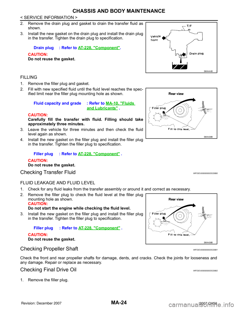
2. Remove the drain plug and gasket to drain the transfer fluid as
shown.
3. Install the new gasket on the drain plug and install the drain plug
in the transfer. Tighten the drain plug to specification.
CAUTION:
Do not reuse the gasket.
FILLING
1. Remove the filler plug and gasket.
2. Fill with new specified fluid until the fluid level reaches the spec-
ified limit near the filler plug mounting hole as shown.
CAUTION:
Carefully fill the transfer with fluid. Filling should take
approximately three minutes.
3. Leave the vehicle for three minutes and then check the fluid
level again as shown.
4. Install the new gasket on the filler plug and install the filler plug
in the transfer. Tighten the filler plug to specification.
CAUTION:
Do not reuse the gasket.
Checking Transfer FluidINFOID:0000000003533880
FLUID LEAKAGE AND FLUID LEVEL
1. Check for any fluid leaks from the transfer assembly or around it and correct as necessary.
2. Remove the filler plug to check the fluid level at the filler plug
mounting hole as shown.
CAUTION:
Do not start the engine while checking the fluid level.
3. Install the new gasket on the filler plug and install the filler plug
in the transfer. Tighten the filler plug to specification.
CAUTION:
Do not reuse the gasket.
Checking Propeller ShaftINFOID:0000000003533881
Check the front and rear propeller shafts for damage, dents, and cracks. Check the joints for looseness and
any damage. Repair or replace as necessary.
Checking Final Drive OilINFOID:0000000003533882
1. Remove the filler plug.Drain plug : Refer to AT-228, "
Component".
SMA444B
Fluid capacity and grade : Refer to MA-10, "Fluids
and Lubricants" .
Filler plug : Refer to AT-228, "
Component" .
SMA439B
Filler plug : Refer to AT-228, "Component" .
SMA439B