set clock INFINITI QX56 2007 Factory User Guide
[x] Cancel search | Manufacturer: INFINITI, Model Year: 2007, Model line: QX56, Model: INFINITI QX56 2007Pages: 3061, PDF Size: 64.56 MB
Page 1500 of 3061

DTC P0456 EVAP CONTROL SYSTEM
EC-417
< SERVICE INFORMATION >
C
D
E
F
G
H
I
J
K
L
MA
EC
N
P O
1. Attach the EVAP service port adapter securely to the EVAP ser-
vice port.
2. Set the pressure pump and a hose.
3. Also set a vacuum gauge via 3-way connector and a hose.
4. Turn ignition switch ON.
5. Connect GST and select Service $08.
6. Using Service $08, control the EVAP canister vent control valve
(close).
7. Apply pressure and make sure the following conditions are sat-
isfied.
Pressure to be applied: 2.7 kPa (20 mmHg, 0.79 inHg)
Time to be waited after the pressure drawn in to the EVAP
system and the pressure to be dropped: 60 seconds and
the pressure should not be dropped more than 0.4 kPa (3
mmHg, 0.12 inHg).
If NG, go to EC-417, "
Diagnosis Procedure" .
If OK, go to next step.
8. Disconnect GST.
9. Start engine and warm it up to normal operating temperature.
10. Turn ignition switch OFF and wait at least 10 seconds.
11. Restart engine and let it idle for 90 seconds.
12. Keep engine speed at 2,000 rpm for 30 seconds.
13. Turn ignition switch OFF.
NOTE:
For more information, refer to GST Instruction Manual.
Diagnosis ProcedureINFOID:0000000003531915
1.CHECK FUEL FILLER CAP DESIGN
1. Turn ignition switch OFF.
2. Check for genuine NISSAN fuel filler cap design.
OK or NG
OK >> GO TO 2.
NG >> Replace with genuine NISSAN fuel filler cap.
2.CHECK FUEL FILLER CAP INSTALLATION
Check that the cap is tightened properly by rotating the cap clockwise.
OK or NG
OK >> GO TO 3.
NG >> 1. Open fuel filler cap, then clean cap and fuel filler neck threads using air blower.
2. Retighten until ratcheting sound is heard.
BBIA0366E
SEF462UI
SEF915U
Page 1809 of 3061

TIMING CHAINEM-39
< SERVICE INFORMATION >
C
DE
F
G H
I
J
K L
M A
EM
NP
O
4. Obtain compression TDC of No. 1 cylinder as follows:
a. Turn the crankshaft pulley clockwise to align the TDC identifica-
tion notch (without paint mark) with the timing indicator on the
front cover.
b. At this time, make sure both intake and exhaust cam lobes of No. 1 cylinder (top front on LH bank) point outside.
• If they do not point outside, turn crankshaft pulley once more.
5. Remove the crankshaft pulley.
a. Loosen the crankshaft pulley bolts using a hammer handle to secure the crankshaft.
b. Remove the crankshaft pulley from the crankshaft using tool. • Remove the crankshaft pulley using suitable tool. Set the boltsin the two bolt holes [M6 x 1.0 mm (0.04 in)] on the front sur-
face.
NOTE:
The dimension between the centers of the two bolt holes is 61
mm (2.40 in).
6. Remove the front cover.
a. Loosen and remove the bolts in the reverse of order shown.
b. Cut the liquid gasket and remove the covers using Tool. CAUTION:
Do not damage mating surfaces.
7. Remove the front oil seal using suitable tool. CAUTION:
Do not damage front cover.
KBIA2476E
KBIA0400J
PBIC0053E
KBIA2477E
Tool number : KV10111100 (J-37228)
KBIA2478E
Page 2262 of 3061

FRONT FOG LAMP
LT-55
< SERVICE INFORMATION >
C
D
E
F
G
H
I
J
L
MA
B
LT
N
O
P
Aiming AdjustmentINFOID:0000000003533400
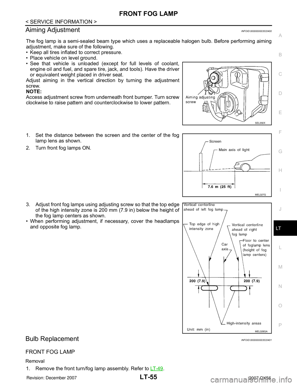
The fog lamp is a semi-sealed beam type which uses a replaceable halogen bulb. Before performing aiming
adjustment, make sure of the following.
• Keep all tires inflated to correct pressure.
• Place vehicle on level ground.
• See that vehicle is unloaded (except for full levels of coolant,
engine oil and fuel, and spare tire, jack, and tools). Have the driver
or equivalent weight placed in driver seat.
Adjust aiming in the vertical direction by turning the adjustment
screw.
NOTE:
Access adjustment screw from underneath front bumper. Turn screw
clockwise to raise pattern and counterclockwise to lower pattern.
1. Set the distance between the screen and the center of the fog
lamp lens as shown.
2. Turn front fog lamps ON.
3. Adjust front fog lamps using adjusting screw so that the top edge
of the high intensity zone is 200 mm (7.9 in) below the height of
the fog lamp centers as shown.
• When performing adjustment, if necessary, cover the headlamps
and opposite fog lamp.
Bulb ReplacementINFOID:0000000003533401
FRONT FOG LAMP
Removal
1. Remove the front turn/fog lamp assembly. Refer to LT- 4 9.
SEL350X
MEL327G
MEL328GA
Page 2329 of 3061

LT-122
< SERVICE INFORMATION >
ILLUMINATION
• to front heated seat switch LH and RH terminal 6
• to VDC OFF switch terminal 4
• to tow mode switch terminal 4
• to headlamp aiming switch terminal 4
• to clock terminal 4 and
• to combination meter terminal 18.
Ground is supplied
• to illumination control switch terminal 3
• to glove box lamp terminal 2
• to door mirror remote control switch terminal 15
• to display control unit terminal 3
• to rear heated seat switches terminal 6
• to electric brake (pre-wiring) terminal 1 (with trailer tow)
• to combination meter terminal 17
• through grounds M57, M61 and M79, and
• to NAVI control unit terminal 1
• to rear air control terminal 3
• to rear audio remote control unit terminal 15
• through grounds B117 and B132.
With power and ground supplied, illumination lamps illuminate.
EXTERIOR LAMP BATTERY SAVER CONTROL
When the combination switch (lighting switch) is in the 1ST or 2ND position (or if auto light system is acti-
vated), and the ignition switch is turned from ON or ACC to OFF, the battery saver control function is activated.
Under this condition, the illumination lamps remain illuminated for 5 minutes, then the illumination lamps are
turned off.
When the lighting switch is turned from OFF to 1ST or 2ND position (or if auto light system is activated) after
illumination lamps are turned off by the battery saver control, the illumination lamps illuminate again.
Exterior lamp battery saver control mode can be changed by the function setting of CONSULT-II.
CAN Communication System DescriptionINFOID:0000000003533470
Refer to LAN-4, "CAN Communication System" .
Page 2499 of 3061

PS-8
< SERVICE INFORMATION >
STEERING WHEEL
CHECKING FRONT WHEEL TURNING ANGLE
When checking front wheel turning angle, refer to FSU-6, "Front Wheel Alignment" .
Removal and InstallationINFOID:0000000003532825
REMOVAL
1. Set the front wheels in the straight-ahead position.
2. Remove the driver air bag module. Refer to SRS-35, "
Removal and Installation".
3. Disconnect steering wheel switches.
4. Remove the steering wheel center nut.
5. Remove the steering wheel using Tools.
CAUTION:
Place a piece of tape across the spiral cable so it will not be
rotated out of position.
6. Inspect the steering wheel near the puller holes for damage. If
damaged, replace the steering wheel.
• Remove steering wheel rear cover and steering wheel
switches, if required.
INSTALLATION
Installation is in the reverse order of removal.
• Align spiral cable correctly when installing steering wheel. Make
sure that the spiral cable is in the neutral position. The neutral
position is detected by turning left 2.5 revolutions from the right
end position and ending with the knob at the top.
• If equipped with VDC, refer to BRC-54, "
Adjustment of Steering
Angle Sensor Neutral Position" for steering angle sensor adjust-
ment.
• After the work is completed, perform self-diagnosis to make sure
no malfunction is detected. Refer to SRS-20, "
SRS Operation
Check".
• Tighten steering wheel center nut to specification. Refer to PS-10,
"Removal and Installation".
CAUTION:
• The spiral cable may snap due to steering operation if the
cable is not installed in the correct position.
• With the steering linkage disconnected, the cable may snap
by turning the steering wheel beyond the limited number of
turns. The spiral cable can be turned counterclockwise about
2.5 turns from the neutral position.Tool number A: J-1859-A
B: J-42578
WHIA0124E
WGIA0038E
PHIA0275E