INFINITI QX56 2007 Factory Service Manual
QX56 2007
INFINITI
INFINITI
https://www.carmanualsonline.info/img/42/57029/w960_57029-0.png
INFINITI QX56 2007 Factory Service Manual
Trending: wheel, service schedule, fuse, spark plugs, compression ratio, load capacity, CD player
Page 2041 of 3061
GW-22
< SERVICE INFORMATION >
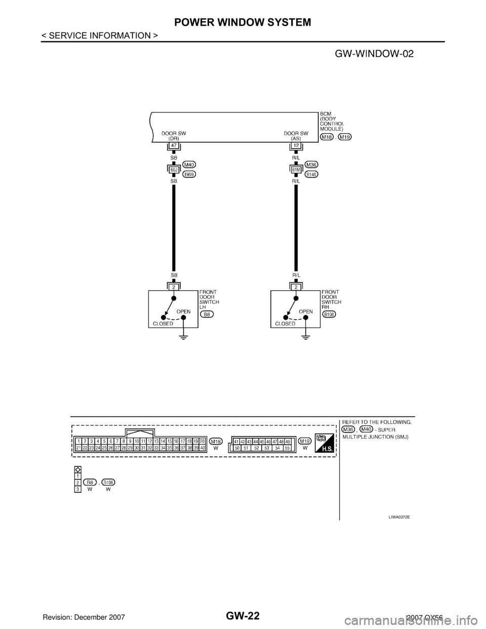
POWER WINDOW SYSTEM
LIWA0372E
Page 2042 of 3061
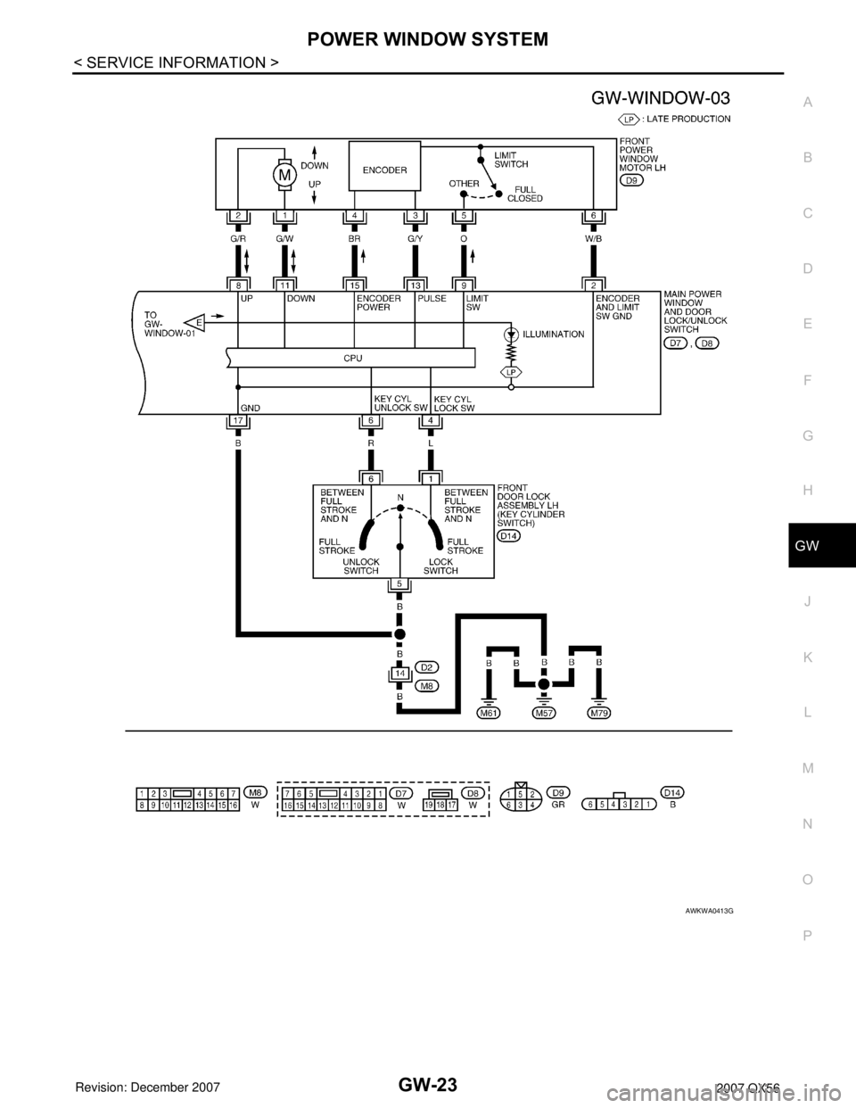
POWER WINDOW SYSTEM
GW-23
< SERVICE INFORMATION >
C
D
E
F
G
H
J
K
L
MA
B
GW
N
O
P
AWKWA0413G
Page 2043 of 3061
GW-24
< SERVICE INFORMATION >
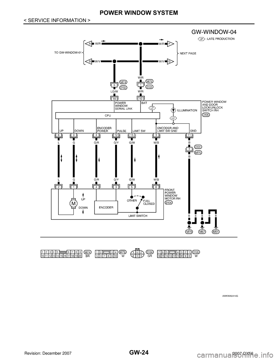
POWER WINDOW SYSTEM
AWKWA0414G
Page 2044 of 3061
POWER WINDOW SYSTEM
GW-25
< SERVICE INFORMATION >
C
D
E
F
G
H
J
K
L
MA
B
GW
N
O
P
AWKWA0477G
Page 2045 of 3061
GW-26
< SERVICE INFORMATION >
POWER WINDOW SYSTEM
AWKWA0478G
Page 2046 of 3061
POWER WINDOW SYSTEM
GW-27
< SERVICE INFORMATION >
C
D
E
F
G
H
J
K
L
MA
B
GW
N
O
P
AWKWA0479G
Page 2047 of 3061
GW-28
< SERVICE INFORMATION >
POWER WINDOW SYSTEM
Main Power Window and Door Lock/Unlock Switch Harness Connector Terminal Lay-
AWKWA0480G
Page 2048 of 3061

POWER WINDOW SYSTEM
GW-29
< SERVICE INFORMATION >
C
D
E
F
G
H
J
K
L
MA
B
GW
N
O
P
outINFOID:0000000003533029
Terminal and Reference Value for Main Power Window and Door Lock/Unlock Switch
INFOID:0000000003533030
LIIA2455E
Terminal Wire Color Item ConditionVoltage (V)
(Approx.)
2 W/B Limit switch and encoder ground — 0
4LFront door key cylinder switch LH
lock signalKey position
(Neutral → Unlocked)5 → 0
6RFront door key cylinder LH switch
unlock signalKey position
(Neutral → Locked)5 → 0
8G/RFront power window motor LH UP
signalWhen power window motor is op-
erated UP Battery voltage
9 O Limit switch signalFront power window LH is be-
tween fully-open and just before
fully-closed position (ON)0
Front power window LH is be-
tween just before fully-closed po-
sition and fully-closed position
(OFF)5
10 W/L RAP signalWhen ignition switch ON Battery voltage
Within 45 seconds after ignition
switch is turned to OFFBattery voltage
More than 45 seconds after igni-
tion switch is turned to OFF0
When front door LH or RH open
or power window timer operates0
11 G / WFront power window motor LH
DOWN signalWhen power window motor is op-
erated DOWN Battery voltage
13 G/Y Encoder pulse signalWhen power window motor oper-
ates
14 LG/W Power window serial linkWhen ignition switch ON or power
window timer operates
OCC3383D
PIIA2344J
Page 2049 of 3061
GW-30
< SERVICE INFORMATION >
POWER WINDOW SYSTEM
Power Window and Door Lock/Unlock Switch RH Harness Connector Terminal Layout
INFOID:0000000003533031
Terminal and Reference Value for Power Window and Door Lock/Unlock Switch RH
INFOID:0000000003533032
15 BR Encoder power supplyWhen ignition switch ON or power
window timer operates10
17 B Ground — 0
19 W/R Battery power supply — Battery voltage Terminal Wire Color Item ConditionVoltage (V)
(Approx.)
LIIA2454E
Terminal Wire Color Item ConditionVoltage (V)
(Approx.)
3 W/B Limit switch and encoder ground — 0
4 G/R Encoder power supplyWhen ignition switch ON or power
window timer operates10
8LFront power window motor RH UP
signalWhen power window motor is op-
erated UP Battery voltage
9GFront power window motor RH
DOWN signalWhen power window motor is op-
erated DOWN Battery voltage
10 W/R Battery power supply — Battery voltage
11 B G r o u n d — 0
12 G/Y Encoder pulse signalWhen power window motor oper-
ates
OCC3383D
Page 2050 of 3061

POWER WINDOW SYSTEM
GW-31
< SERVICE INFORMATION >
C
D
E
F
G
H
J
K
L
MA
B
GW
N
O
P
Terminal and Reference Value for BCMINFOID:0000000003533033
Refer to BCS-11, "Terminal and Reference Value for BCM".
Work FlowINFOID:0000000003533034
1. Check the symptom and customer's requests.
2. Understand the outline of system. Refer to GW-15, "
System Description".
3. According to the trouble diagnosis chart, repair or replace the cause of the malfunction.
Refer to GW-32, "
Trouble Diagnosis Symptom Chart".
4. Does power window system operate normally? Yes, GO TO 5, If No, GO TO 3.
5. Inspection End.
CONSULT-II Function (BCM)INFOID:0000000003533035
CONSULT-II can display each diagnostic item using the diagnostic test modes shown following.
CONSULT-II START PROCEDURE
Refer to GI-36, "CONSULT-II Start Procedure".
ACTIVE TEST
15 G/W Limit switch signalRear power window RH is be-
tween fully-open and just before
fully-closed position (ON)0
Rear power window RH is be-
tween just before fully-closed po-
sition and fully-closed position
(OFF)5
16 LG/W Power window serial linkWhen ignition switch is ON or
power window timer operating Terminal Wire Color Item ConditionVoltage (V)
(Approx.)
PIIA2344J
BCM diagnostic
test itemDiagnostic mode Content
Inspection by partWORK SUPPORTSupports inspections and adjustments. Commands are transmitted to the BCM for
setting the status suitable for required operation, input/output signals are received
from the BCM and received data is displayed.
DATA MONITOR Displays BCM input/output data in real time.
ACTIVE TEST Operation of electrical loads can be checked by sending drive signal to them.
SELF-DIAG RESULTS Displays BCM self-diagnosis results.
CAN DIAG SUPPORT MNTR The results of transmit/receive diagnosis of CAN communication can be read.
ECU PART NUMBER BCM part number can be read.
CONFIGURATION Performs BCM configuration read/write functions.
Trending: wiper blades, service interval, radio, weight, brake sensor, warning, fuel pump


