fuel pump INFINITI QX56 2007 Factory Service Manual
[x] Cancel search | Manufacturer: INFINITI, Model Year: 2007, Model line: QX56, Model: INFINITI QX56 2007Pages: 3061, PDF Size: 64.56 MB
Page 107 of 3061

A/T CONTROL SYSTEM
AT-37
< SERVICE INFORMATION >
D
E
F
G
H
I
J
K
L
MA
B
AT
N
O
P
When shifting from the lock-up released state to the lock-up applied state, the current output to the torque con-
verter clutch solenoid is controlled with the TCM. In this way, when shifting to the lock-up applied state, the
torque converter clutch is temporarily set to the half-clutched state to reduce the shock.
Half-clutched State
• The current output from the TCM to the torque converter clutch solenoid is varied to gradually increase the
torque converter clutch solenoid pressure.
In this way, the lock-up apply pressure gradually rises and while the torque converter clutch piston is put into
half-clutched status, the torque converter clutch piston operating pressure is increased and the coupling is
completed smoothly.
Slip Lock-up Control
• In the slip region, the torque converter clutch solenoid current is controlled with the TCM to put it into the
half-clutched state. This absorbs the engine torque fluctuation and lock-up operates from low speed.
This raises the fuel efficiency for 4th and 5th gears at both low speed and when the accelerator has a low
degree of opening.
Engine Brake ControlINFOID:0000000003532236
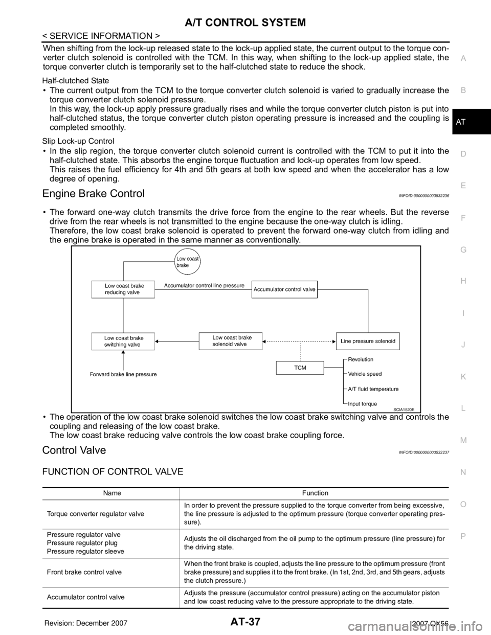
• The forward one-way clutch transmits the drive force from the engine to the rear wheels. But the reverse
drive from the rear wheels is not transmitted to the engine because the one-way clutch is idling.
Therefore, the low coast brake solenoid is operated to prevent the forward one-way clutch from idling and
the engine brake is operated in the same manner as conventionally.
• The operation of the low coast brake solenoid switches the low coast brake switching valve and controls the
coupling and releasing of the low coast brake.
The low coast brake reducing valve controls the low coast brake coupling force.
Control ValveINFOID:0000000003532237
FUNCTION OF CONTROL VALVE
SCIA1520E
Name Function
Torque converter regulator valveIn order to prevent the pressure supplied to the torque converter from being excessive,
the line pressure is adjusted to the optimum pressure (torque converter operating pres-
sure).
Pressure regulator valve
Pressure regulator plug
Pressure regulator sleeveAdjusts the oil discharged from the oil pump to the optimum pressure (line pressure) for
the driving state.
Front brake control valveWhen the front brake is coupled, adjusts the line pressure to the optimum pressure (front
brake pressure) and supplies it to the front brake. (In 1st, 2nd, 3rd, and 5th gears, adjusts
the clutch pressure.)
Accumulator control valveAdjusts the pressure (accumulator control pressure) acting on the accumulator piston
and low coast reducing valve to the pressure appropriate to the driving state.
Page 571 of 3061

AUDIO
AV-31
< SERVICE INFORMATION >
C
D
E
F
G
H
I
J
L
MA
B
AV
N
O
P
• Loss of power to the satellite radio tuner (factory installed)
• Open or short in the REQ1, TXD, or RXD circuits.
If the satellite antenna is disconnected or inoperative, the display unit will display ANTENNA.
Noise InspectionINFOID:0000000003533674
The vehicle itself can be a source of noise if noise prevention parts or electrical equipment is malfunctioning.
Check if noise is caused and/or changed by engine speed, ignition switch turned to each position, and opera-
tion of each piece of electrical equipment, and determine the cause.
NOTE:
The source of the noise can be found easily by listening to the noise while removing the fuses of electrical
components, one by one.
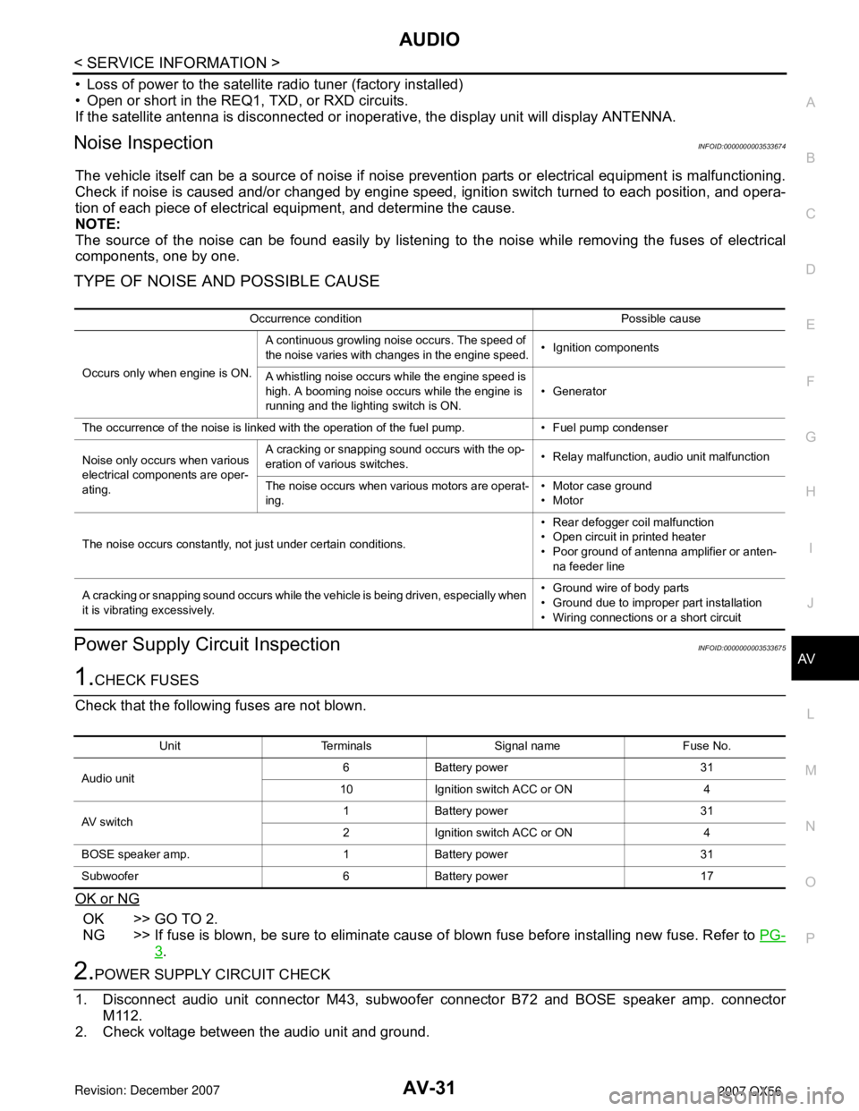
TYPE OF NOISE AND POSSIBLE CAUSE
Power Supply Circuit InspectionINFOID:0000000003533675
1.CHECK FUSES
Check that the following fuses are not blown.
OK or NG
OK >> GO TO 2.
NG >> If fuse is blown, be sure to eliminate cause of blown fuse before installing new fuse. Refer to PG-
3.
2.POWER SUPPLY CIRCUIT CHECK
1. Disconnect audio unit connector M43, subwoofer connector B72 and BOSE speaker amp. connector
M112.
2. Check voltage between the audio unit and ground.
Occurrence condition Possible cause
Occurs only when engine is ON.A continuous growling noise occurs. The speed of
the noise varies with changes in the engine speed.• Ignition components
A whistling noise occurs while the engine speed is
high. A booming noise occurs while the engine is
running and the lighting switch is ON.• Generator
The occurrence of the noise is linked with the operation of the fuel pump. • Fuel pump condenser
Noise only occurs when various
electrical components are oper-
ating.A cracking or snapping sound occurs with the op-
eration of various switches.• Relay malfunction, audio unit malfunction
The noise occurs when various motors are operat-
ing.• Motor case ground
•Motor
The noise occurs constantly, not just under certain conditions.• Rear defogger coil malfunction
• Open circuit in printed heater
• Poor ground of antenna amplifier or anten-
na feeder line
A cracking or snapping sound occurs while the vehicle is being driven, especially when
it is vibrating excessively.• Ground wire of body parts
• Ground due to improper part installation
• Wiring connections or a short circuit
Unit Terminals Signal name Fuse No.
Audio unit6 Battery power 31
10 Ignition switch ACC or ON 4
AV switch1 Battery power 31
2 Ignition switch ACC or ON 4
BOSE speaker amp. 1 Battery power 31
Subwoofer 6 Battery power 17
Page 1016 of 3061

COMBINATION METERSDI-5
< SERVICE INFORMATION >
C
DE
F
G H
I
J
L
M A
B
DI
N
O P
COMBINATION METERS
Component Parts and Har ness Connector LocationINFOID:0000000003533479
System DescriptionINFOID:0000000003533480
UNIFIED METER CONTROL UNIT
• Speedometer, odometer, tachometer, fuel gauge, oil pressure gauge, voltage gauge, A/T oil temperature
gauge, and water temperature gauge are controlled by the unified meter control unit, which is built into the
combination meter.
• Warning indicators are controlled by signals drawn fr om the CAN communication system, BCM (body control
module), and components connected directly to the combination meter.
• Digital meter is adopted for odometer/trip meters*, as well as the A/T position indicator display. *The record of the odometer is kept ev en if the battery cable is disconnected.
• Odometer/trip meters and A/T indicator segments can be checked in diagnosis mode.
• Meters/gauges can be checked in diagnosis mode.
Illumination control
The unified meter control unit outputs the speedometer, odometer/trip meters, tachometer, oil pressure gauge,
voltage meter, A/T indicator, A/T temperature gauge, fuel and temperature gauge lighting when the ignition
switch is turned on. When the lighting switch is turned on, the illumination control switch can be used to adjust
the brightness of the combination meter illuminati on and the odometer/trip meters and meter illumination.
When the ignition switch is turned from the OFF to the ON position, the combination meter dial lighting will
remain off for 0.7 seconds. For additional combination meter illumination control information, refer to LT-120,
"System Description".
1. IPDM E/R E122 2. Combination meter M24 3. Fuel level sensor unit and fuel pump
C5 (view with inspection hole cover
removed)
4. ECM E16 (view with battery re- moved) 5. ABS actuator and electric unit (con-
trol unit) E125 6. Oil pressure switch F4
A. Oil pan (upper)
7. A/T assembly F9
WKIA5718E
Page 1017 of 3061
![INFINITI QX56 2007 Factory Service Manual
DI-6
< SERVICE INFORMATION >
COMBINATION METERS
POWER SUPPLY AND GROUND CIRCUIT
Power is supplied at all times
• through 10A fuse [No.19, located in the fuse block (J/B)]
• to combination meter t INFINITI QX56 2007 Factory Service Manual
DI-6
< SERVICE INFORMATION >
COMBINATION METERS
POWER SUPPLY AND GROUND CIRCUIT
Power is supplied at all times
• through 10A fuse [No.19, located in the fuse block (J/B)]
• to combination meter t](/img/42/57029/w960_57029-1016.png)
DI-6
< SERVICE INFORMATION >
COMBINATION METERS
POWER SUPPLY AND GROUND CIRCUIT
Power is supplied at all times
• through 10A fuse [No.19, located in the fuse block (J/B)]
• to combination meter terminal 8.
With the ignition switch in the ON or START position, power is supplied
• through 10A fuse [No.14, located in the fuse block (J/B)]
• to combination meter terminal 24.
Ground is supplied
• to combination meter terminal 17
• through body grounds M57, M61 and M79.
WATER TEMPERATURE GAUGE
The water temperature gauge indicates the engine coolant temperature.
ECM provides an engine coolant temperature signal to combination meter via CAN communication lines.
ENGINE OIL PRESSURE GAUGE
The engine oil pressure gauge indicates whether the engine oil pressure is low or normal.
The oil pressure gauge is controlled by the IPDM E/R (intelligent power distribution module engine room). Low
oil pressure causes oil pressure switch terminal 1 to provide ground to IPDM E/R terminal 42. The IPDM E/R
then signals the combination meter (unified meter control unit) via CAN communication lines and a low oil
pressure indication is displayed by the oil pressure gauge.
A/T OIL TEMPERATURE GAUGE
The A/T oil temperature gauge indicates the A/T fluid temperature.
TCM (transmission control module) provides an A/T flui d temperature signal to combination meter via CAN
communication lines.
VOLTAGE GAUGE
The voltage gauge indicates the battery/charging system voltage.
The voltage gauge is regulated by the unified meter control unit.
TA C H O M E T E R
The tachometer indicates engine speed in revolutions per minute (rpm).
ECM provides an engine speed signal to combination meter via CAN communication lines.
FUEL GAUGE
The fuel gauge indicates the approximate fuel level in the fuel tank.
The fuel gauge is regulated by the unified meter control unit and a variable resistor signal supplied
• to combination meter terminal 15.
• through fuel level sensor unit and fuel pump terminal 2
• through fuel level sensor unit and fuel pump terminal 5
• from combination meter terminal 16
SPEEDOMETER
ABS actuator and electric unit (contro l unit) provides a vehicle speed signal to the combination meter via CAN
communication lines.
ODO/TRIP METER
The vehicle speed signal and the memory signals from the meter memory circuit are processed by the combi-
nation meter and the mileage is displayed.
How to Change the Display
Refer to Owner's Manual for odo/tr ip meter operating instructions.
CAN COMMUNICATION SYSTEM DESCRIPTION
Refer to LAN-4.
Page 1030 of 3061

COMBINATION METERSDI-19
< SERVICE INFORMATION >
C
DE
F
G H
I
J
L
M A
B
DI
N
O P
• Depending on vehicle position or driving circumstance, the fuel in the tank shifts and the indication may fluc-
tuate.
• If the vehicle is fueled with the ignition switch ON, the indication will update slowly.
• If the vehicle is tilted when the ignition switch is turned ON, fuel in the tank may flow to one direction result-
ing in a change of reading.
LOW-FUEL WARNING LAMP
Depending on vehicle posture or driving circumstances, the fuel level in the tank varies, and the warning lamp
ON timing may be changed.
1.CHECK SELF-DIAGNOSIS
Perform the combination meter self-diagnosis. Refer to DI-12, "
Self-Diagnosis Mode of Combination Meter".
OK or NG
OK >> GO TO 2.
NG >> Replace the combination meter. Refer to IP-10, "
Removal and Installation".
2.CHECK HARNESS CONNECTOR
1. Turn the ignition switch OFF.
2. Check combination meter and fuel level sensor unit and fuel pump terminals (meter-side, and harness-
side) for poor connection.
OK or NG
OK >> GO TO 3.
NG >> Repair or replace terminals or connectors.
3.CHECK HARNESS CONNECTOR OUTPUT SIGNAL
1. Disconnect fuel level sensor unit and fuel pump connector.
2. Turn ignition switch ON.
3. Check voltage between combination meter harness connector M24 terminal 15 and ground.
OK or NG
OK >> GO TO 4.
NG >> Replace the combination meter. Refer to IP-10,
"Removal and Installation".
4.CHECK HARNESS FOR OPEN OR SHORT CIRCUIT
1. Turn the ignition switch OFF.
2. Disconnect combination meter connector M24.
3. Check continuity between combination meter harness connector M24 (B) terminal 15 and fuel level sensor unit and fuel pump
harness connector C5 (A) terminal 2.
4. Check continuity between fuel level sensor unit and fuel pump harness connector C5 (A) terminal 2 and ground.
OK or NG
OK >> GO TO 5.
NG >> Repair harness or connector.
5.CHECK FUEL LEVEL SENSOR CIRCUIT Battery voltage should exist.
WKIA1816E
Continuity should exist.
Continuity should not exist.
WKIA4617E
Page 1031 of 3061

DI-20
< SERVICE INFORMATION >
COMBINATION METERS
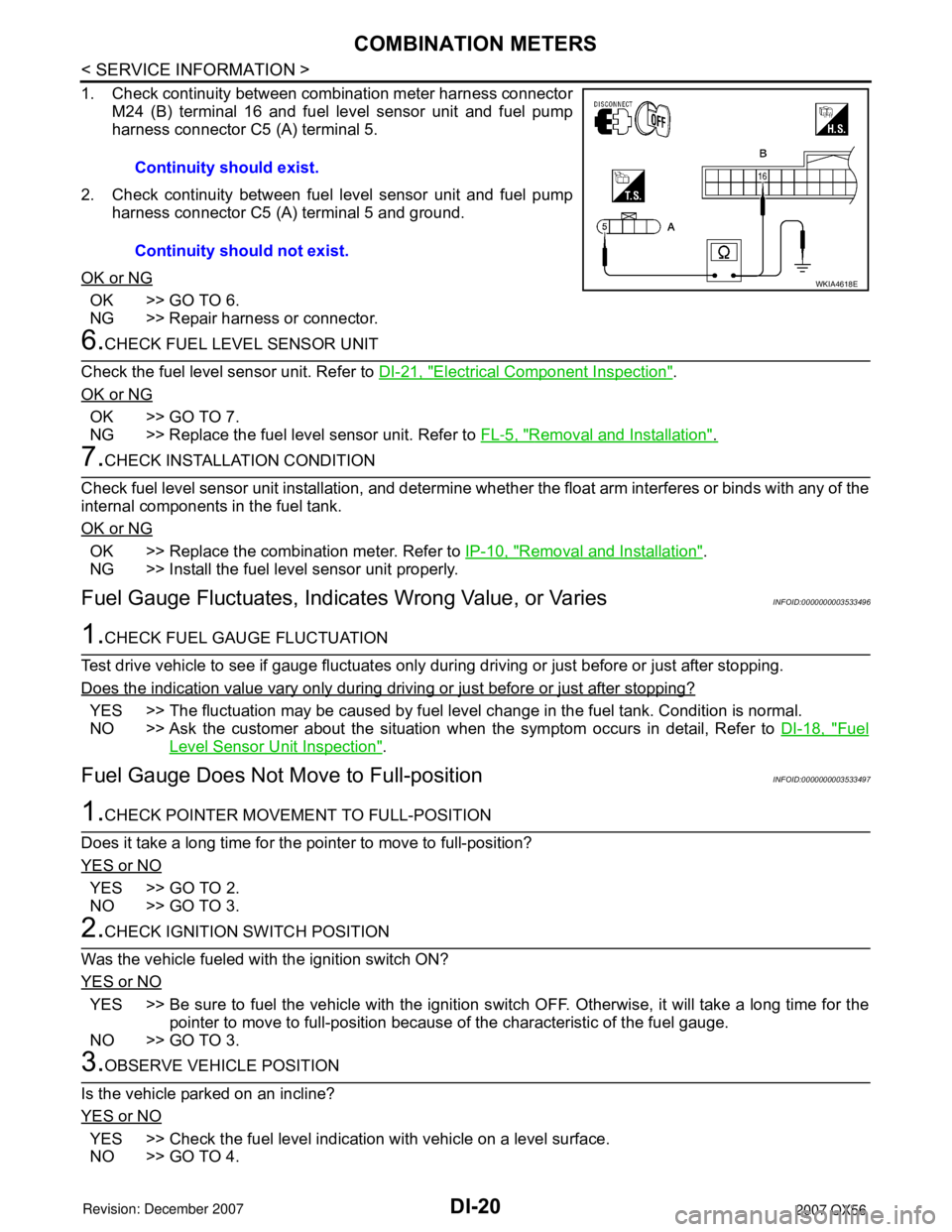
1. Check continuity between combination meter harness connectorM24 (B) terminal 16 and fuel level sensor unit and fuel pump
harness connector C5 (A) terminal 5.
2. Check continuity between fuel level sensor unit and fuel pump harness connector C5 (A) terminal 5 and ground.
OK or NG
OK >> GO TO 6.
NG >> Repair harness or connector.
6.CHECK FUEL LEVEL SENSOR UNIT
Check the fuel level sensor unit. Refer to DI-21, "
Electrical Component Inspection".
OK or NG
OK >> GO TO 7.
NG >> Replace the fuel level sensor unit. Refer to FL-5, "
Removal and Installation".
7.CHECK INSTALLATION CONDITION
Check fuel level sensor unit installation, and determine whet her the float arm interferes or binds with any of the
internal components in the fuel tank.
OK or NG
OK >> Replace the combination meter. Refer to IP-10, "Removal and Installation".
NG >> Install the fuel level sensor unit properly.
Fuel Gauge Fluctuat es, Indicates Wrong Value, or VariesINFOID:0000000003533496
1.CHECK FUEL GAUGE FLUCTUATION
Test drive vehicle to see if gauge fluctuates only during driving or just before or just after stopping.
Does the indication value vary only during driving or just before or just after stopping?
YES >> The fluctuation may be caused by fuel leve l change in the fuel tank. Condition is normal.
NO >> Ask the customer about the situation when the symptom occurs in detail, Refer to DI-18, "
Fuel
Level Sensor Unit Inspection".
Fuel Gauge Does Not Move to Full-positionINFOID:0000000003533497
1.CHECK POINTER MOVEME NT TO FULL-POSITION
Does it take a long time for the pointer to move to full-position?
YES or NO
YES >> GO TO 2.
NO >> GO TO 3.
2.CHECK IGNITION SWITCH POSITION
Was the vehicle fueled with the ignition switch ON?
YES or NO
YES >> Be sure to fuel the vehicle with the ignition s witch OFF. Otherwise, it will take a long time for the
pointer to move to full-position because of the characteristic of the fuel gauge.
NO >> GO TO 3.
3.OBSERVE VEHICLE POSITION
Is the vehicle parked on an incline?
YES or NO
YES >> Check the fuel level indication with vehicle on a level surface.
NO >> GO TO 4. Continuity should exist.
Continuity should not exist.
WKIA4618E
Page 1032 of 3061

COMBINATION METERS
DI-21
< SERVICE INFORMATION >
C
D
E
F
G
H
I
J
L
MA
B
DI
N
O
P
4.CHECK POINTER MOVEMENT TO EMPTY-POSITION
During driving, does the fuel gauge move gradually toward empty-position?
YES or NO
YES >> Check the fuel level sensor unit. Refer to DI-21, "Electrical Component Inspection".
NO >> Check fuel level sensor unit installation, and determine whether the float arm interferes or binds
with any of the internal components in the fuel tank.
Electrical Component InspectionINFOID:0000000003533498
FUEL LEVEL SENSOR UNIT CHECK
For removal, refer to FL-5, "Removal and Installation".
Check Fuel Level Sensor Unit and Fuel Pump
Check resistance between fuel level sensor unit and fuel pump con-
nector terminals 2 and 5.
*1 and *2: When float rod is in contact with stopper.
OIL PRESSURE SWITCH CHECK
Check continuity between the oil pressure switch and body ground.
Removal and Installation of Combination MeterINFOID:0000000003533499
Refer to "Removal and Installation of Combination Meter" for removal and installation procedures.
Terminals Float position mm (in)Resistance
value Ω
(Approx.)
25*1 Empty 25.86 (1.02) 81.66
*2 Full 254.6 (10.02) 6.98
LKIA0402E
ConditionOil pressure
kPa (kg/cm2, psi)Continuity
Engine stopped Less than 29 (0.3, 4) Yes
Engine running More than 29 (0.3, 4) No
ELF0044D
Page 1091 of 3061

EC-8
DTC Confirmation Procedure ................................567
Wiring Diagram ......................................................569
Diagnosis Procedure .............................................570
Component Inspection ...........................................572
Removal and Installation .......................................573
DTC P2135 TP SENSOR .................................574
Component Description .........................................574
CONSULT-II Reference Value in Data Monitor
Mode ......................................................................
574
On Board Diagnosis Logic .....................................574
DTC Confirmation Procedure ................................574
Wiring Diagram ......................................................576
Diagnosis Procedure .............................................577
Component Inspection ...........................................579
Removal and Installation .......................................580
DTC P2138 APP SENSOR ..............................581
Component Description .........................................581
CONSULT-II Reference Value in Data Monitor
Mode ......................................................................
581
On Board Diagnosis Logic .....................................581
DTC Confirmation Procedure ................................582
Wiring Diagram ......................................................583
Diagnosis Procedure .............................................584
Component Inspection ...........................................587
Removal and Installation .......................................587
DTC P2A00, P2A03 A/F SENSOR 1 ...............588
Component Description .........................................588
CONSULT-II Reference Value in Data Monitor
Mode ......................................................................
588
On Board Diagnosis Logic .....................................588
DTC Confirmation Procedure ................................588
Wiring Diagram ......................................................590
Diagnosis Procedure .............................................593
Removal and Installation .......................................596
ASCD BRAKE SWITCH ..................................597
Component Description .........................................597
CONSULT-II Reference Value in Data Monitor
Mode ......................................................................
597
Wiring Diagram ......................................................598
Diagnosis Procedure .............................................599
Component Inspection ...........................................602
ASCD INDICATOR ..........................................603
Component Description .........................................603
CONSULT-II Reference Value in Data Monitor
Mode ......................................................................
603
Wiring Diagram ......................................................604
Diagnosis Procedure .............................................604
ELECTRICAL LOAD SIGNAL .........................606
Description .............................................................606
CONSULT-II Reference Value in Data Monitor
Mode ......................................................................
606
Diagnosis Procedure .............................................606
FUEL INJECTOR ..............................................608
Component Description ........................................608
CONSULT-II Reference Value in Data Monitor
Mode .....................................................................
608
Wiring Diagram .....................................................609
Diagnosis Procedure .............................................610
Component Inspection ..........................................612
Removal and Installation .......................................612
FUEL PUMP .....................................................613
Description ............................................................613
CONSULT-II Reference Value in Data Monitor
Mode .....................................................................
613
Wiring Diagram .....................................................614
Diagnosis Procedure .............................................615
Component Inspection ..........................................617
Removal and Installation .......................................618
ICC BRAKE SWITCH .......................................619
Component Description ........................................619
CONSULT-II Reference Value in Data Monitor
Mode .....................................................................
619
Wiring Diagram .....................................................620
Diagnosis Procedure .............................................621
Component Inspection ..........................................624
IGNITION SIGNAL ............................................626
Component Description ........................................626
Wiring Diagram .....................................................627
Diagnosis Procedure .............................................632
Component Inspection ..........................................635
Removal and Installation .......................................637
REFRIGERANT PRESSURE SENSOR ...........638
Component Description ........................................638
Wiring Diagram .....................................................639
Diagnosis Procedure .............................................640
Removal and Installation .......................................642
MIL AND DATA LINK CONNECTOR ...............643
Wiring Diagram .....................................................643
SERVICE DATA AND SPECIFICATIONS
(SDS) ................................................................
645
Fuel Pressure ........................................................645
Idle Speed and Ignition Timing .............................645
Calculated Load Value ..........................................645
Mass Air Flow Sensor ...........................................645
Intake Air Temperature Sensor .............................645
Engine Coolant Temperature Sensor ...................645
A/F Sensor 1 Heater .............................................645
Heated Oxygen sensor 2 Heater ..........................645
Crankshaft Position Sensor (POS) .......................646
Camshaft Position Sensor (PHASE) .....................646
Throttle Control Motor ...........................................646
Fuel Injector ..........................................................646
Fuel Pump .............................................................646
Page 1103 of 3061

EC-20
< SERVICE INFORMATION >
PRECAUTIONS
•Do not operate fuel pump when there is no fuel in lines.
•Tighten fuel hose clamps to the specified torque.
•Do not depress accelerator pedal when starting.
•Immediately after starting, do not rev up engine unnecessar-
ily.
•Do not rev up engine just prior to shutdown.
•When installing C.B. ham radio or a mobile phone, be sure to
observe the following as it may adversely affect electronic
control systems depending on installation location.
-Keep the antenna as far as possible from the electronic con-
trol units.
-Keep the antenna feeder line more than 20 cm (8 in) away
from the harness of electronic controls.
Do not let them run parallel for a long distance.
-Adjust the antenna and feeder line so that the standing-wave
radio can be kept smaller.
-Be sure to ground the radio to vehicle body.
BBIA0402E
SEF709Y
SEF708Y
Page 1120 of 3061

EVAPORATIVE EMISSION SYSTEM
EC-37
< SERVICE INFORMATION >
C
D
E
F
G
H
I
J
K
L
MA
EC
N
P O
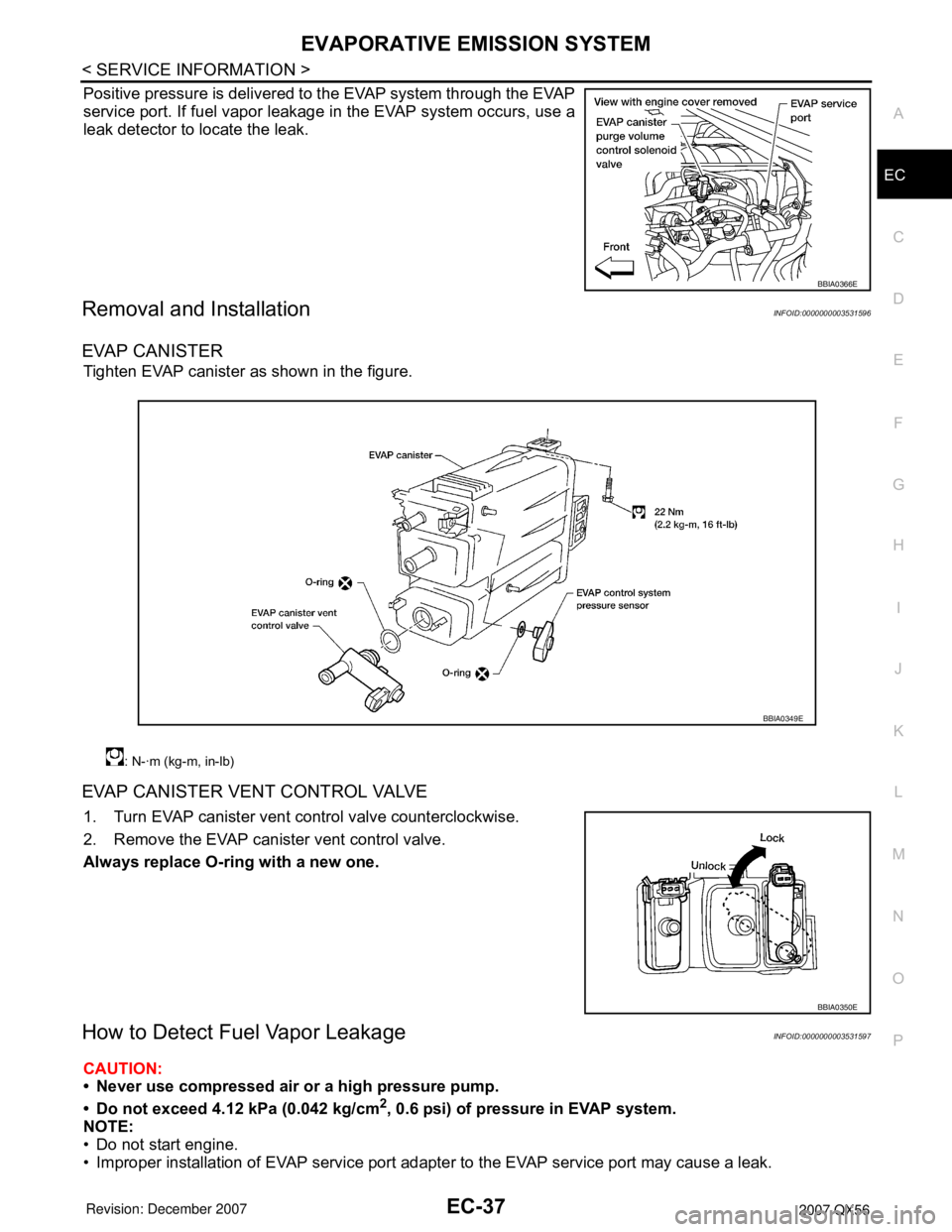
Positive pressure is delivered to the EVAP system through the EVAP
service port. If fuel vapor leakage in the EVAP system occurs, use a
leak detector to locate the leak.
Removal and InstallationINFOID:0000000003531596
EVAP CANISTER
Tighten EVAP canister as shown in the figure.
EVAP CANISTER VENT CONTROL VALVE
1. Turn EVAP canister vent control valve counterclockwise.
2. Remove the EVAP canister vent control valve.
Always replace O-ring with a new one.
How to Detect Fuel Vapor LeakageINFOID:0000000003531597
CAUTION:
• Never use compressed air or a high pressure pump.
• Do not exceed 4.12 kPa (0.042 kg/cm
2, 0.6 psi) of pressure in EVAP system.
NOTE:
• Do not start engine.
• Improper installation of EVAP service port adapter to the EVAP service port may cause a leak.
BBIA0366E
: N-·m (kg-m, in-lb)
BBIA0349E
BBIA0350E