ECU INFINITI QX56 2007 Factory Service Manual
[x] Cancel search | Manufacturer: INFINITI, Model Year: 2007, Model line: QX56, Model: INFINITI QX56 2007Pages: 3061, PDF Size: 64.56 MB
Page 2776 of 3061
SRS-6
< SERVICE INFORMATION >
SUPPLEMENTAL RESTRAINT SYSTEM (SRS)
Front Seat Belt Pre-tensioner with Load Limiter
INFOID:0000000003532858
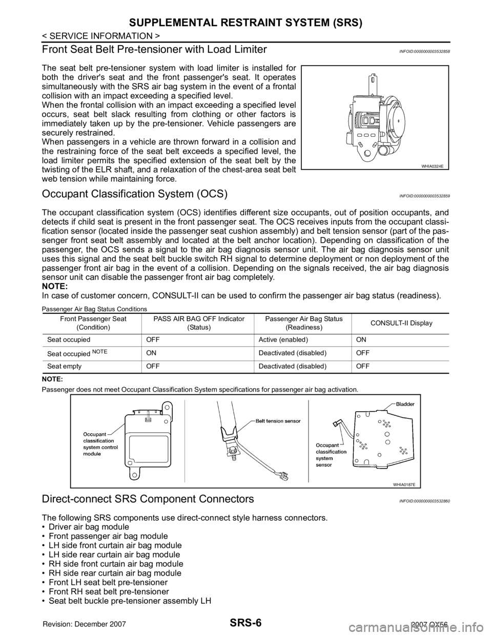
The seat belt pre-tensioner system with load limiter is installed for
both the driver's seat and the front passenger's seat. It operates
simultaneously with the SRS air bag system in the event of a frontal
collision with an impact exceeding a specified level.
When the frontal collision with an impact exceeding a specified level
occurs, seat belt slack resulting from clothing or other factors is
immediately taken up by the pre-tensioner. Vehicle passengers are
securely restrained.
When passengers in a vehicle are thrown forward in a collision and
the restraining force of the seat belt exceeds a specified level, the
load limiter permits the specified extension of the seat belt by the
twisting of the ELR shaft, and a relaxation of the chest-area seat belt
web tension while maintaining force.
Occupant Classification System (OCS)INFOID:0000000003532859
The occupant classification system (OCS) identifies different size occupants, out of position occupants, and
detects if child seat is present in the front passenger seat. The OCS receives inputs from the occupant classi-
fication sensor (located inside the passenger seat cushion assembly) and belt tension sensor (part of the pas-
senger front seat belt assembly and located at the belt anchor location). Depending on classification of the
passenger, the OCS sends a signal to the air bag diagnosis sensor unit. The air bag diagnosis sensor unit
uses this signal and the seat belt buckle switch RH signal to determine deployment or non deployment of the
passenger front air bag in the event of a collision. Depending on the signals received, the air bag diagnosis
sensor unit can disable the passenger front air bag completely.
NOTE:
In case of customer concern, CONSULT-II can be used to confirm the passenger air bag status (readiness).
Passenger Air Bag Status Conditions
NOTE:
Passenger does not meet Occupant Classification System specifications for passenger air bag activation.
Direct-connect SRS Component ConnectorsINFOID:0000000003532860
The following SRS components use direct-connect style harness connectors.
• Driver air bag module
• Front passenger air bag module
• LH side front curtain air bag module
• LH side rear curtain air bag module
• RH side front curtain air bag module
• RH side rear curtain air bag module
• Front LH seat belt pre-tensioner
• Front RH seat belt pre-tensioner
• Seat belt buckle pre-tensioner assembly LH
WHIA0324E
Front Passenger Seat
(Condition)PASS AIR BAG OFF Indicator
(Status)Passenger Air Bag Status
(Readiness)CONSULT-II Display
Seat occupied OFF Active (enabled) ON
Seat occupied
NOTEON Deactivated (disabled) OFF
Seat empty OFF Deactivated (disabled) OFF
WHIA0187E
Page 2788 of 3061
SRS-18
< SERVICE INFORMATION >
TROUBLE DIAGNOSIS
CONSULT-II Function
INFOID:0000000003532866
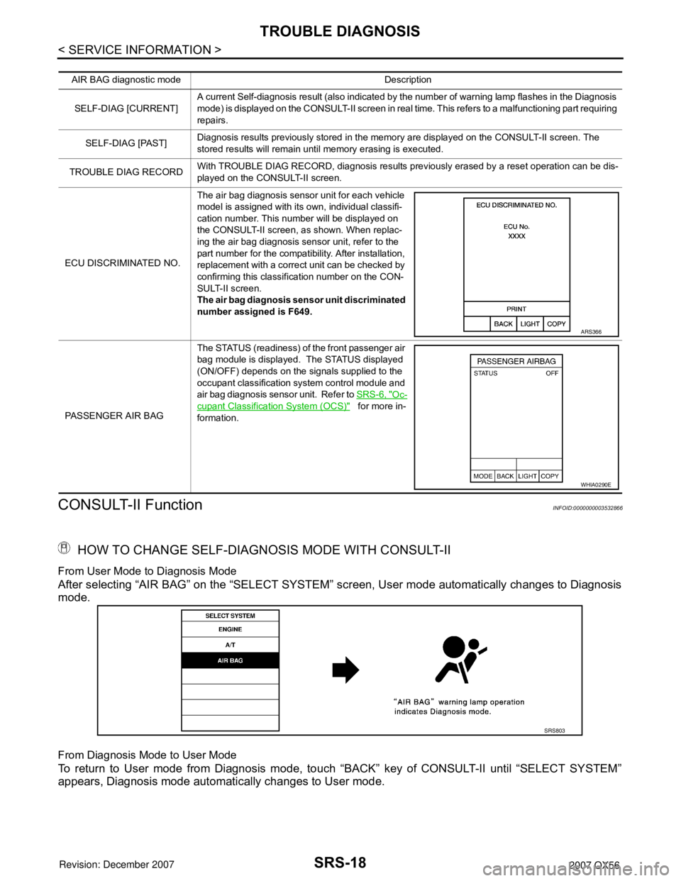
HOW TO CHANGE SELF-DIAGNOSIS MODE WITH CONSULT-II
From User Mode to Diagnosis Mode
After selecting “AIR BAG” on the “SELECT SYSTEM” screen, User mode automatically changes to Diagnosis
mode.
From Diagnosis Mode to User Mode
To return to User mode from Diagnosis mode, touch “BACK” key of CONSULT-II until “SELECT SYSTEM”
appears, Diagnosis mode automatically changes to User mode.
AIR BAG diagnostic mode Description
SELF-DIAG [CURRENT]A current Self-diagnosis result (also indicated by the number of warning lamp flashes in the Diagnosis
mode) is displayed on the CONSULT-II screen in real time. This refers to a malfunctioning part requiring
repairs.
SELF-DIAG [PAST]Diagnosis results previously stored in the memory are displayed on the CONSULT-II screen. The
stored results will remain until memory erasing is executed.
TROUBLE DIAG RECORDWith TROUBLE DIAG RECORD, diagnosis results previously erased by a reset operation can be dis-
played on the CONSULT-II screen.
ECU DISCRIMINATED NO.The air bag diagnosis sensor unit for each vehicle
model is assigned with its own, individual classifi-
cation number. This number will be displayed on
the CONSULT-II screen, as shown. When replac-
ing the air bag diagnosis sensor unit, refer to the
part number for the compatibility. After installation,
replacement with a correct unit can be checked by
confirming this classification number on the CON-
SULT-II screen.
The air bag diagnosis sensor unit discriminated
number assigned is F649.
PASSENGER AIR BAGThe STATUS (readiness) of the front passenger air
bag module is displayed. The STATUS displayed
(ON/OFF) depends on the signals supplied to the
occupant classification system control module and
air bag diagnosis sensor unit. Refer to SRS-6, "
Oc-
cupant Classification System (OCS)" for more in-
formation.
ARS366
WHIA0290E
SRS803
Page 2811 of 3061
FRONT PASSENGER AIR BAG MODULE
SRS-41
< SERVICE INFORMATION >
C
D
E
F
G
I
J
K
L
MA
B
SRS
N
O
P
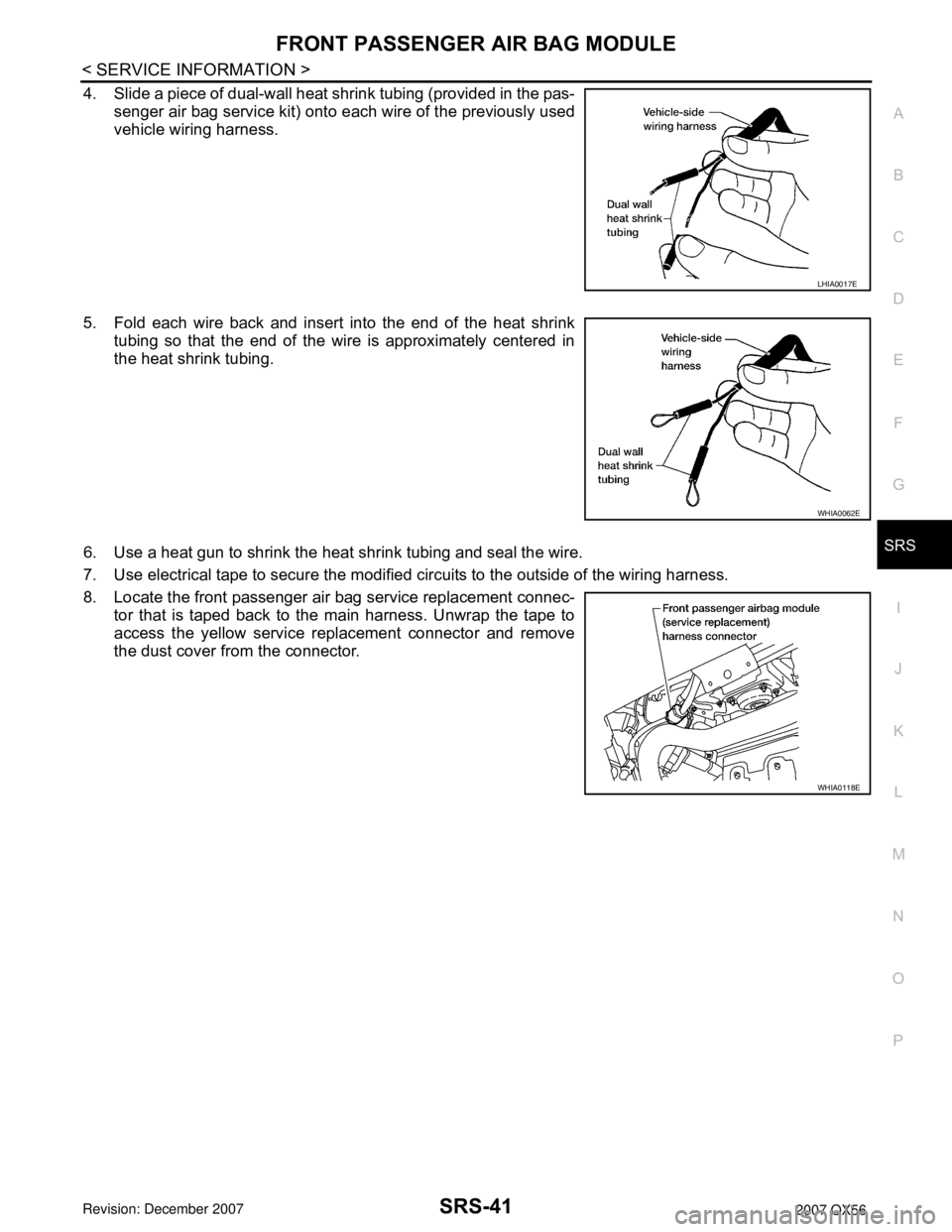
4. Slide a piece of dual-wall heat shrink tubing (provided in the pas-
senger air bag service kit) onto each wire of the previously used
vehicle wiring harness.
5. Fold each wire back and insert into the end of the heat shrink
tubing so that the end of the wire is approximately centered in
the heat shrink tubing.
6. Use a heat gun to shrink the heat shrink tubing and seal the wire.
7. Use electrical tape to secure the modified circuits to the outside of the wiring harness.
8. Locate the front passenger air bag service replacement connec-
tor that is taped back to the main harness. Unwrap the tape to
access the yellow service replacement connector and remove
the dust cover from the connector.
LHIA0017E
WHIA0062E
WHIA0118E
Page 2817 of 3061
DIAGNOSIS SENSOR UNIT
SRS-47
< SERVICE INFORMATION >
C
D
E
F
G
I
J
K
L
MA
B
SRS
N
O
P
DIAGNOSIS SENSOR UNIT
Removal and InstallationINFOID:0000000003532880
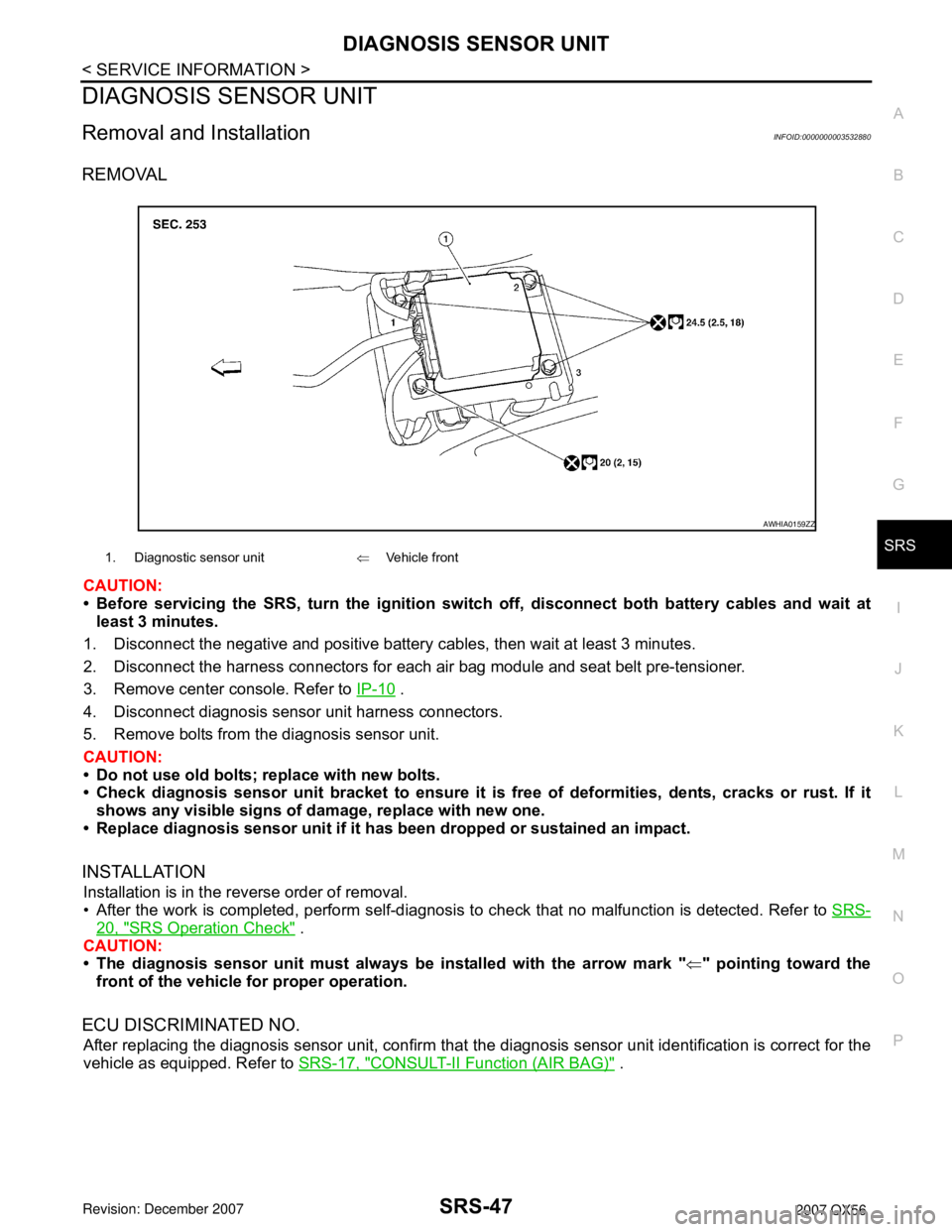
REMOVAL
CAUTION:
• Before servicing the SRS, turn the ignition switch off, disconnect both battery cables and wait at
least 3 minutes.
1. Disconnect the negative and positive battery cables, then wait at least 3 minutes.
2. Disconnect the harness connectors for each air bag module and seat belt pre-tensioner.
3. Remove center console. Refer to IP-10
.
4. Disconnect diagnosis sensor unit harness connectors.
5. Remove bolts from the diagnosis sensor unit.
CAUTION:
• Do not use old bolts; replace with new bolts.
• Check diagnosis sensor unit bracket to ensure it is free of deformities, dents, cracks or rust. If it
shows any visible signs of damage, replace with new one.
• Replace diagnosis sensor unit if it has been dropped or sustained an impact.
INSTALLATION
Installation is in the reverse order of removal.
• After the work is completed, perform self-diagnosis to check that no malfunction is detected. Refer to SRS-
20, "SRS Operation Check" .
CAUTION:
• The diagnosis sensor unit must always be installed with the arrow mark "⇐" pointing toward the
front of the vehicle for proper operation.
ECU DISCRIMINATED NO.
After replacing the diagnosis sensor unit, confirm that the diagnosis sensor unit identification is correct for the
vehicle as equipped. Refer to SRS-17, "
CONSULT-II Function (AIR BAG)" .
1. Diagnostic sensor unit⇐Vehicle front
AWHIA0159ZZ
Page 2864 of 3061

TF-42
< SERVICE INFORMATION >
TROUBLE DIAGNOSIS
CAUTION:
When using a circuit tester to measure voltage for inspection, be sure not to extend forcibly any connector terminals.
CONSULT-II Function (ALL MODE AWD/4WD)INFOID:0000000003532527
FUNCTION
CONSULT-II can display each diagnostic item using the diagnostic test modes shown following.
41 RTransfer motor relay moni-
tor• Accelerator pedal
depressed
• Vehicle stopped
• Engine running
• Brake pedal de-
pressed4WD shift switch: 2WD 0V
4WD shift switch: AUTO or 4LO (A/T selec-
tor lever “P” or “N” position)0V
(Battery volt-
age for approx.
2 sec. after
shifting to “P”
and “N”.)
4WD shift switch: AUTO or 4LO (Except for
A/T selector lever “P” or “N” position)Battery voltage
4WD shift switch: 4H (A/T selector lever
“P” position)0V
(Battery volt-
age for approx.
2 sec. after
shifting to “P”.)
4WD shift switch: 4H (Except for A/T selec-
tor lever “P” position)Battery voltage
42 P/GTransfer shift low relay
monitor• Vehicle stopped
• Engine running
• A/T selector lever
“N” position
• Brake pedal de-
pressed4WD shift switch: 4LO to 4H (“Wait” func-
tion is operating.)Battery voltage
Except the above 0V
43 G/Y Wait detection switch• Vehicle stopped
• Engine running
• A/T selector lever
“N” position
• Brake pedal de-
pressed4WD shift switch: 2WD, AUTO or 4H Battery voltage
4WD shift switch: 4H to 4LO (While actua-
tor motor is operating.)Battery voltage
→ 0V
4WD shift switch: 4LO to 4H (While actua-
tor motor is operating.)0V → Battery
voltage
4WD shift switch: 4LO 0V
44 LG/BActuator position switch 1
(Low)• Vehicle stopped
• Engine running
• A/T selector lever
“N” position
• Brake pedal de-
pressed4WD shift switch: 4LO 0V
4WD shift switch: 2WD, AUTO or 4H Battery voltage
45 B Ground Always 0V
47 WPower supply
(Memory back-up)Ignition switch: ON Battery voltage
Ignition switch: OFF Battery voltage Te r m i n a lWire
colorItem Condition Data (Approx.)
ALL MODE AWD/4WD diag-
nostic modeDescription
SELF-DIAG RESULTS Displays transfer control unit self-diagnosis results.
DATA MONITOR Displays transfer control unit input/output data in real time.
WORK SUPPORTSupports inspections and adjustments. Commands are transmitted to the transfer control unit for set-
ting the status suitable for required operation, input/output signals are received from the transfer control
unit and received data is displayed.
CAN DIAG SUPPORT MNTR The results of transmit/receive diagnosis of CAN communication can be read.
ECU PART NUMBER Transfer control unit part number can be read.
Page 2867 of 3061

TROUBLE DIAGNOSIS
TF-45
< SERVICE INFORMATION >
C
E
F
G
H
I
J
K
L
MA
B
TF
N
O
P
2. Start engine and select “SELF-DIAG RESULTS” mode for “ALL MODE AWD/4WD” with CONSULT-II.
3. Touch “ERASE” on CONSULT-II screen to erase DTC memory.
CAUTION:
If memory cannot be erased, perform applicable diagnosis.
DATA MONITOR MODE
Operation Procedure
Refer to GI-36, "CONSULT-II Start Procedure".
Display Item List
×: Standard –: Not applicable
Monitored item (Unit)Monitor item selection
Remarks
ECU INPUT
SIGNALSMAIN
SIGNALSSELEC-
TION FROM
MENU
VHCL/S SEN·FR [km/h] or [mph]×–×Wheel speed calculated by ABS actuator and
electric unit (control unit).
Signal input with CAN communication line.
VHCL/S SEN·RR [km/h] or [mph]×–×Wheel speed calculated by TCM.
Signal input with CAN communication line.
ENGINE SPEED [rpm]×–×Engine speed calculated by ECM.
Signal input with CAN communication line.
THRTL POS SEN [V]×–×Accelerator pedal position (APP) sensor sig-
nal voltage is displayed.
Signal input with CAN communication line.
FLUID TEMP SE [V]×–×Transfer fluid temperature sensor signal volt-
age is displayed.
BATTERY VOLT [V]×–×Power supply voltage for transfer control unit.
2WD SWITCH [ON/OFF]×–×4WD shift switch status is displayed.
AUTO SWITCH [ON/OFF]×–×4WD shift switch status is displayed.
LOCK SWITCH [ON/OFF]×–×4WD shift switch status is displayed.
(LOCK means 4H of 4WD shift switch.)
4L SW [ON/OFF]×–×4WD shift switch status is displayed.
(4L means 4LO of 4WD shift switch.)
N POSI SW TF [ON/OFF]×–×Neutral-4LO switch signal status is displayed.
ATP SWITCH [ON/OFF]×–×ATP switch signal status is displayed.
WAIT DETCT SW [ON/OFF]×–×Wait detection switch status is displayed.
LINE PRES SW [ON/OFF]×–×Line pressure switch status is displayed.
CL PRES SW [ON / OFF]×–×Clutch pressure switch status is displayed.
N POSI SW AT [ON/OFF]זדN” position signal of A/T PNP switch status is
displayed.
Signal input with CAN communication line.
R POSI SW AT [ON/OFF]זדR” position signal of A/T PNP switch status is
displayed.
Signal input with CAN communication line.
P POSI SW AT [ON/OFF]זדP” position signal of A/T PNP switch status is
displayed.
Signal input with CAN communication line.
ABS OPER SW [ON/OFF]×–×ABS operation signal status is displayed.
Signal input with CAN communication line.
VDC OPER SW [ON/OFF]×–×VDC operation signal status is displayed.
Signal input with CAN communication line.
TCS OPER SW [ON/OFF]×–×TCS operation signal status is displayed.
Signal input with CAN communication line.
Page 2868 of 3061
![INFINITI QX56 2007 Factory Service Manual TF-46
< SERVICE INFORMATION >
TROUBLE DIAGNOSIS
THROTTLE POSI [0.0/8] –××Thottle position status is displayed.
Signal input with CAN communication line.
4WD MODE [AUTO/LOCK/2WD/4L] –××Contro INFINITI QX56 2007 Factory Service Manual TF-46
< SERVICE INFORMATION >
TROUBLE DIAGNOSIS
THROTTLE POSI [0.0/8] –××Thottle position status is displayed.
Signal input with CAN communication line.
4WD MODE [AUTO/LOCK/2WD/4L] –××Contro](/img/42/57029/w960_57029-2867.png)
TF-46
< SERVICE INFORMATION >
TROUBLE DIAGNOSIS
THROTTLE POSI [0.0/8] –××Thottle position status is displayed.
Signal input with CAN communication line.
4WD MODE [AUTO/LOCK/2WD/4L] –××Control status of 4WD recognized by transfer
control unit. (AUTO, 4H, 2WD or 4LO)
VHCL/S COMP [km/h] or [mph] –××Vehicle speed recognized by transfer control
unit.
COMP CL TORQ [kgm] –××Calculated torque recognized by transfer con-
trol unit.
DUTY SOLENOID [%] –××Control value of clutch pressure solenoid.
2-4WD SOL [ON/OFF] –××Output condition to 2-4WD solenoid.
2-4WD SOL MON [ON/OFF] – –×Check signal for transfer control unit signal
output.
MOTOR RELAY [ON/OFF] –××Transfer motor relay signal status is dis-
played.
MOTOR RELAY MON [ON/OFF] – –×Check signal for transfer control unit signal
output.
4WD FAIL LAMP [ON/OFF] –××Control status of 4WD warning lamp is dis-
played.
2WD IND [ON/OFF] – –×Control status of 4WD shift indicator lamp
(2WD indicator lamp) is displayed.
AUTO IND [ON/OFF] – –×Control status of 4WD shift indicator lamp
(2WD and AUTO indicator lamp) is displayed.
LOCK IND [ON/OFF] – –×Control status of 4WD shift indicator lamp
(2WD, AUTO and Lock indicator) is displayed.
4L IND [ON/OFF] – –×Control status of 4LO indicator lamp is dis-
played.
ATP IND [ON/OFF] – –×Control status of ATP warning lamp is dis-
played.
SHIFT POS SW1 [ON/OFF]×–×Actuator position switch 1 (Low) signal status
is displayed.
SHIFT POS SW2 [ON/OFF]×–×Actuator position switch 2 (high) signal status
is displayed.
SHIFT ACT1 [ON/OFF] –××Output condition to actuator motor (clockwise)
SHIFT AC MON1 [ON/OFF]×–×Check signal for transfer control unit signal
output
SHIFT ACT2 [ON/OFF] –××Output condition to actuator motor (counter-
clockwise)
SHIFT AC MON2 [ON/OFF]×–×Check signal for transfer control unit signal
output
T/F F SPEED [km/h] or [mph]×–×Displayed, but do not use.
A/T R SPEED [km/h] or [mph]×–×Output shaft revolution signal (Revolution
sensor) calculated by TCM.
Signal input with CAN communication line.
AT GEAR POSI [1/2/3/4/5]
×–×A/T actual gear position is displayed.
Voltage [V] – –×The value measured by the voltage probe is
displayed. Monitored item (Unit)Monitor item selection
Remarks
ECU INPUT
SIGNALSMAIN
SIGNALSSELEC-
TION FROM
MENU
Page 2869 of 3061
TROUBLE DIAGNOSIS
TF-47
< SERVICE INFORMATION >
C
E
F
G
H
I
J
K
L
MA
B
TF
N
O
PWORK SUPPORT
When there is no problem with transfer and 4WD system, following symptom in “AUTO” mode may be claimed
by a customer.
• Vibration when accelerating on a low µ road (snow-covered or icy road)
It is possible to deal with these symptoms by changing “CLUTCH FORCE RELEASE LIMIT VALUE”. How-
ever, be careful when changing the values because it may adversely affect driving performance.
NOTE:
A slight shock is felt at a few hertz as if it were being pushed lightly from behind.
Operation Procedure
1. Refer to GI-36, "CONSULT-II Start Procedure".
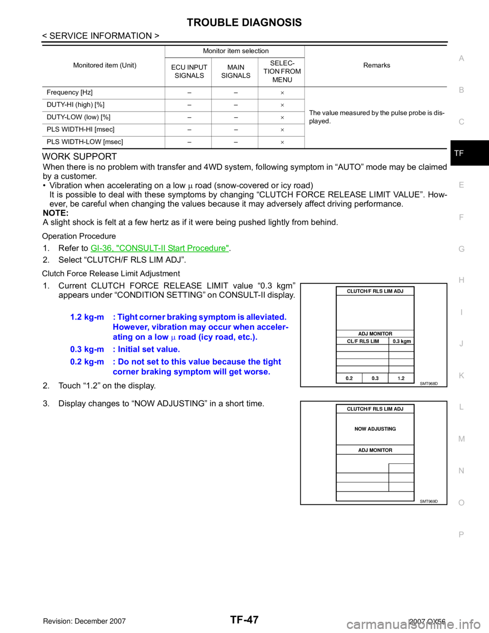
2. Select “CLUTCH/F RLS LIM ADJ”.
Clutch Force Release Limit Adjustment
1. Current CLUTCH FORCE RELEASE LIMIT value “0.3 kgm”
appears under “CONDITION SETTING” on CONSULT-II display.
2. Touch “1.2” on the display.
3. Display changes to “NOW ADJUSTING” in a short time.
Frequency [Hz] – –×
The value measured by the pulse probe is dis-
played. DUTY-HI (high) [%] – –×
DUTY-LOW (low) [%] – –×
PLS WIDTH-HI [msec] – –×
PLS WIDTH-LOW [msec] – –× Monitored item (Unit)Monitor item selection
Remarks
ECU INPUT
SIGNALSMAIN
SIGNALSSELEC-
TION FROM
MENU
1.2 kg-m : Tight corner braking symptom is alleviated.
However, vibration may occur when acceler-
ating on a low µ road (icy road, etc.).
0.3 kg-m : Initial set value.
0.2 kg-m : Do not set to this value because the tight
corner braking symptom will get worse.
SMT968D
SMT969D
Page 2966 of 3061
TF-144
< SERVICE INFORMATION >
TRANSFER ASSEMBLY
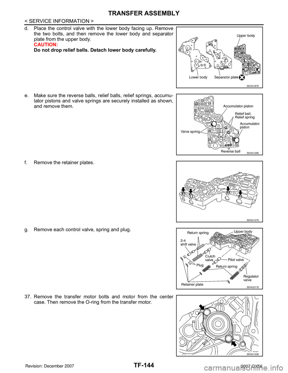
d. Place the control valve with the lower body facing up. Remove
the two bolts, and then remove the lower body and separator
plate from the upper body.
CAUTION:
Do not drop relief balls. Detach lower body carefully.
e. Make sure the reverse balls, relief balls, relief springs, accumu-
lator pistons and valve springs are securely installed as shown,
and remove them.
f. Remove the retainer plates.
g. Remove each control valve, spring and plug.
37. Remove the transfer motor bolts and motor from the center
case. Then remove the O-ring from the transfer motor.
SDIA3187E
SDIA2126E
SDIA2127E
SDIA3317E
SDIA2133E
Page 2974 of 3061
TF-152
< SERVICE INFORMATION >
TRANSFER ASSEMBLY
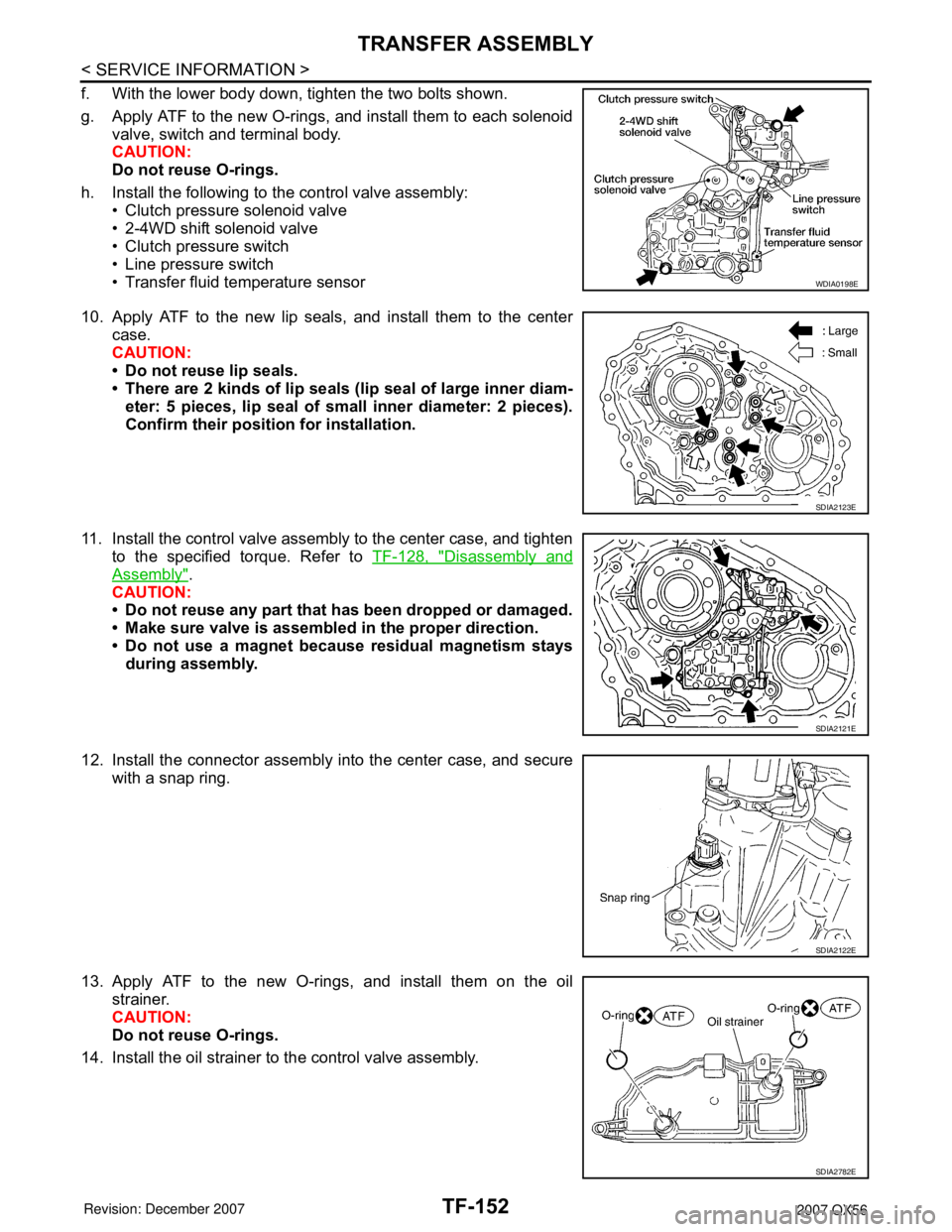
f. With the lower body down, tighten the two bolts shown.
g. Apply ATF to the new O-rings, and install them to each solenoid
valve, switch and terminal body.
CAUTION:
Do not reuse O-rings.
h. Install the following to the control valve assembly:
• Clutch pressure solenoid valve
• 2-4WD shift solenoid valve
• Clutch pressure switch
• Line pressure switch
• Transfer fluid temperature sensor
10. Apply ATF to the new lip seals, and install them to the center
case.
CAUTION:
• Do not reuse lip seals.
• There are 2 kinds of lip seals (lip seal of large inner diam-
eter: 5 pieces, lip seal of small inner diameter: 2 pieces).
Confirm their position for installation.
11. Install the control valve assembly to the center case, and tighten
to the specified torque. Refer to TF-128, "
Disassembly and
Assembly".
CAUTION:
• Do not reuse any part that has been dropped or damaged.
• Make sure valve is assembled in the proper direction.
• Do not use a magnet because residual magnetism stays
during assembly.
12. Install the connector assembly into the center case, and secure
with a snap ring.
13. Apply ATF to the new O-rings, and install them on the oil
strainer.
CAUTION:
Do not reuse O-rings.
14. Install the oil strainer to the control valve assembly.
WDIA0198E
SDIA2123E
SDIA2121E
SDIA2122E
SDIA2782E