tire pressure INFINITI QX56 2007 Factory Service Manual
[x] Cancel search | Manufacturer: INFINITI, Model Year: 2007, Model line: QX56, Model: INFINITI QX56 2007Pages: 3061, PDF Size: 64.56 MB
Page 25 of 3061
![INFINITI QX56 2007 Factory Service Manual ACS-12
< SERVICE INFORMATION >[ICC]
LASER BEAM AIMING ADJUSTMENT
LASER BEAM AIMING ADJUSTMENT
Outline of Laser Beam Aiming Adjustment ProcedureINFOID:0000000003533782
CAUTION:
• The laser beam aimin INFINITI QX56 2007 Factory Service Manual ACS-12
< SERVICE INFORMATION >[ICC]
LASER BEAM AIMING ADJUSTMENT
LASER BEAM AIMING ADJUSTMENT
Outline of Laser Beam Aiming Adjustment ProcedureINFOID:0000000003533782
CAUTION:
• The laser beam aimin](/img/42/57029/w960_57029-24.png)
ACS-12
< SERVICE INFORMATION >[ICC]
LASER BEAM AIMING ADJUSTMENT
LASER BEAM AIMING ADJUSTMENT
Outline of Laser Beam Aiming Adjustment ProcedureINFOID:0000000003533782
CAUTION:
• The laser beam aiming adjustment cannot be performed without CONSULT-II.
• The laser beam aiming adjustment must be performed every time the ICC sensor is removed,
installed or has been moved as a result of a collision.
1. Prepare the vehicle and the work area.
2. Set up the ICC target board. For details, refer to Technical Service Bulletin.
3. Adjust the sensor following the procedure on CONSULT-II.
4. Check system operation after the adjustment.
PreparationINFOID:0000000003533783
• Place the vehicle on level ground. Shift the transmission into "P" position and release the parking brake.
• Adjust the tire pressure to the specified value.
• See that there is no load in the vehicle. Coolant, engine oil and fuel should be filled to correct level.
• Check that the vehicle suspension has been adjusted to the standard height by the load leveling rear air sus-
pension system. Refer to RSU-10, "
Basic Inspection" .
• Clean the sensor with a soft cloth.
Setting up the ICC Target BoardINFOID:0000000003533784
CAUTION:
Accuracy in setting up the ICC target board is essential for the laser beam aiming adjustment. For
details, refer to Technical Service Bulletin.
ADJUSTING HEIGHT OF THE TARGET
1. Attach a triangle scale as shown.Tool number : KV99110100 (J-45718)
LKIA0632E
WKIA1849E
Page 124 of 3061

AT-54
< SERVICE INFORMATION >
TROUBLE DIAGNOSIS
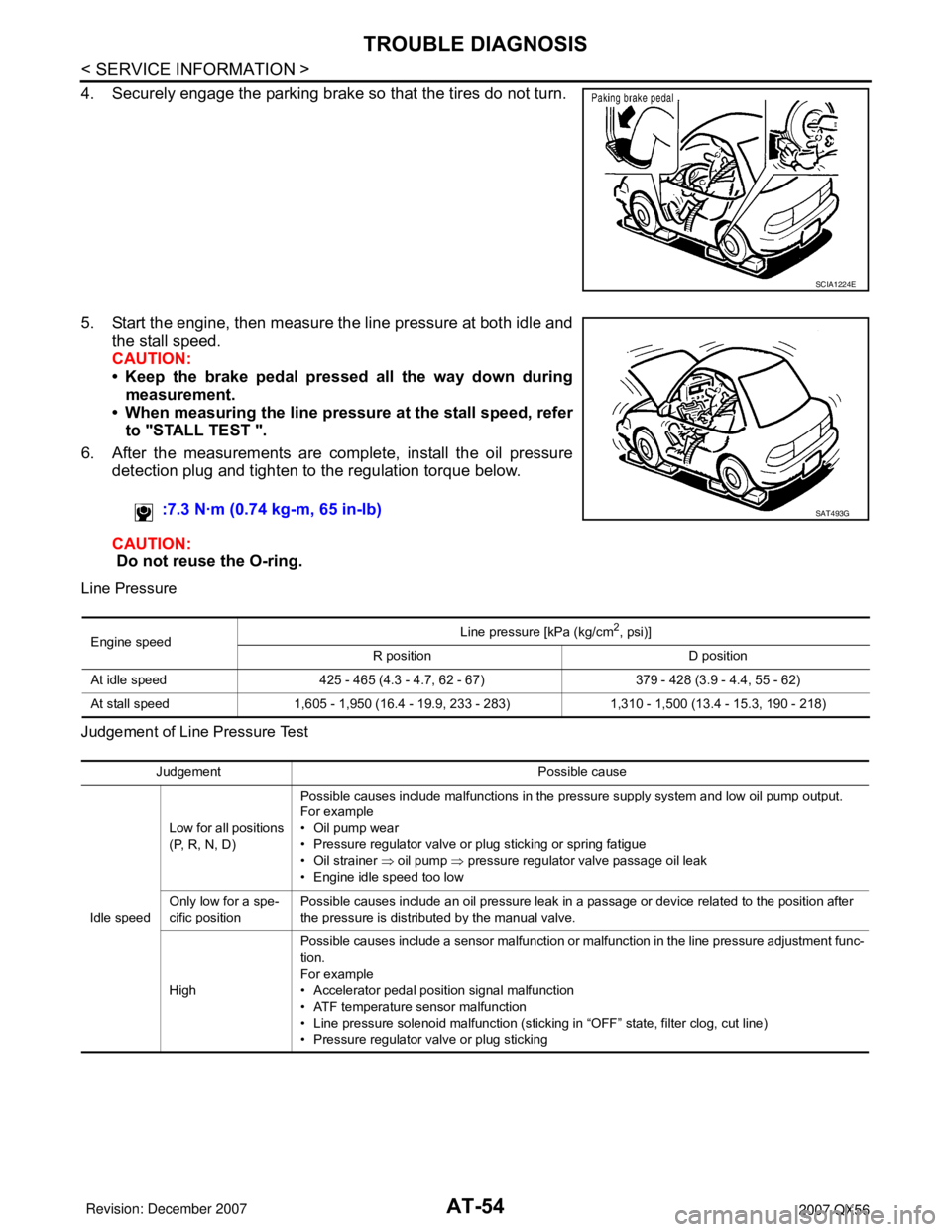
4. Securely engage the parking brake so that the tires do not turn.
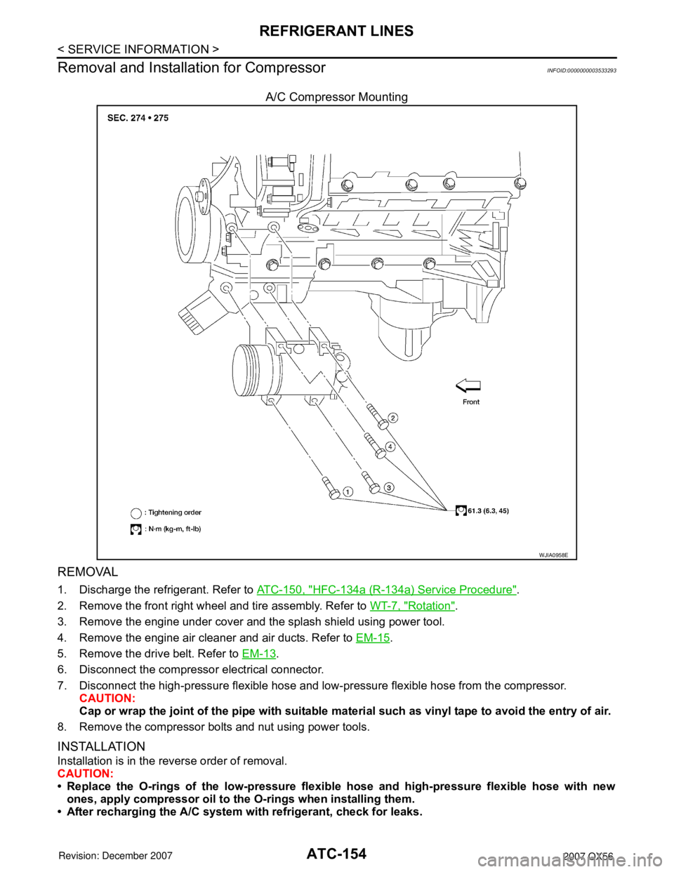
5. Start the engine, then measure the line pressure at both idle and
the stall speed.
CAUTION:
• Keep the brake pedal pressed all the way down during
measurement.
• When measuring the line pressure at the stall speed, refer
to "STALL TEST ".
6. After the measurements are complete, install the oil pressure
detection plug and tighten to the regulation torque below.
CAUTION:
Do not reuse the O-ring.
Line Pressure
Judgement of Line Pressure Test
SCIA1224E
:7.3 N·m (0.74 kg-m, 65 in-lb)SAT493G
Engine speedLine pressure [kPa (kg/cm
2, psi)]
R position D position
At idle speed 425 - 465 (4.3 - 4.7, 62 - 67) 379 - 428 (3.9 - 4.4, 55 - 62)
At stall speed 1,605 - 1,950 (16.4 - 19.9, 233 - 283) 1,310 - 1,500 (13.4 - 15.3, 190 - 218)
Judgement Possible cause
Idle speedLow for all positions
(P, R, N, D)Possible causes include malfunctions in the pressure supply system and low oil pump output.
For example
•Oil pump wear
• Pressure regulator valve or plug sticking or spring fatigue
• Oil strainer ⇒ oil pump ⇒ pressure regulator valve passage oil leak
• Engine idle speed too low
Only low for a spe-
cific positionPossible causes include an oil pressure leak in a passage or device related to the position after
the pressure is distributed by the manual valve.
HighPossible causes include a sensor malfunction or malfunction in the line pressure adjustment func-
tion.
For example
• Accelerator pedal position signal malfunction
• ATF temperature sensor malfunction
• Line pressure solenoid malfunction (sticking in “OFF” state, filter clog, cut line)
• Pressure regulator valve or plug sticking
Page 524 of 3061

ATC-154
< SERVICE INFORMATION >
REFRIGERANT LINES
Removal and Installation for Compressor
INFOID:0000000003533293
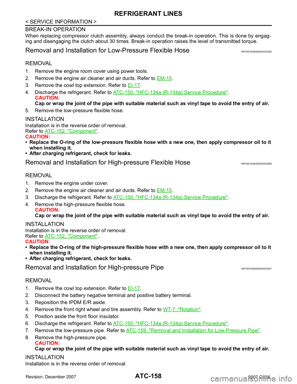
A/C Compressor Mounting
REMOVAL
1. Discharge the refrigerant. Refer to ATC-150, "HFC-134a (R-134a) Service Procedure".
2. Remove the front right wheel and tire assembly. Refer to WT-7, "
Rotation".
3. Remove the engine under cover and the splash shield using power tool.
4. Remove the engine air cleaner and air ducts. Refer to EM-15
.
5. Remove the drive belt. Refer to EM-13
.
6. Disconnect the compressor electrical connector.
7. Disconnect the high-pressure flexible hose and low- pressure flexible hose from the compressor.
CAUTION:
Cap or wrap the joint of the pipe with suitable mate rial such as vinyl tape to avoid the entry of air.
8. Remove the compressor bolts and nut using power tools.
INSTALLATION
Installation is in the reverse order of removal.
CAUTION:
• Replace the O-rings of the low-pressure flexibl e hose and high-pressure flexible hose with new
ones, apply compressor oil to the O-rings when installing them.
• After recharging the A/C system with refrigerant, check for leaks.
WJIA0958E
Page 528 of 3061

ATC-158
< SERVICE INFORMATION >
REFRIGERANT LINES
BREAK-IN OPERATION
When replacing compressor clutch assembly, always conduct the break-in operation. This is done by engag-
ing and disengaging the clutch about 30 times. Break-in operation raises the level of transmitted torque.
Removal and Installation for Low-Pressure Flexible HoseINFOID:0000000003533295
REMOVAL
1. Remove the engine room cover using power tools.
2. Remove the engine air cleaner and air ducts. Refer to EM-15
.
3. Remove the cowl top extension. Refer to EI-17
.
4. Discharge the refrigerant. Refer to ATC-150, "
HFC-134a (R-134a) Service Procedure".
CAUTION:
Cap or wrap the joint of the pipe with suitable mate rial such as vinyl tape to avoid the entry of air.
5. Remove the low-pressure flexible hose.
INSTALLATION
Installation is in the reverse order of removal.
Refer to ATC-152, "
Component".
CAUTION:
• Replace the O-ring of the low-pr essure flexible hose with a new one, then apply compressor oil to it
when installing it.
• After charging refrigerant, check for leaks.
Removal and Installation for High-pressure Flexible HoseINFOID:0000000003533296
REMOVAL
1. Remove the engine under cover.
2. Remove the engine air cleaner and air ducts. Refer to EM-15
.
3. Discharge the refrigerant. Refer to ATC-150, "
HFC-134a (R-134a) Service Procedure".
4. Remove the high-pressure flexible hose. CAUTION:
Cap or wrap the joint of the pipe with suitable mate rial such as vinyl tape to avoid the entry of air.
INSTALLATION
Installation is in the reverse order of removal.
Refer to ATC-152, "
Component".
CAUTION:
• Replace the O-ring of the high-pressure flexible hose with a new one, then apply compressor oil to it
when installing it.
• After charging refrigerant, check for leaks.
Removal and Installation for High-pressure PipeINFOID:0000000003533297
REMOVAL
1. Remove the cowl top extension. Refer to EI-17.
2. Disconnect the battery negative terminal and positive battery terminal.
3. Reposition the IPDM E/R aside.
4. Remove the front right wheel and tire assembly. Refer to WT-7, "
Rotation".
5. Position aside the front floor insulator.
6. Discharge the refrigerant. Refer to ATC-150, "
HFC-134a (R-134a) Service Procedure".
7. Remove the low-pressure pipe. Refer to ATC-159, "
Removal and Installation for Low-Pressure Pipe".
8. Remove the high-pressure pipe. CAUTION:
Cap or wrap the joint of the pipe with suitable mate rial such as vinyl tape to avoid the entry of air.
INSTALLATION
Installation is in the reverse order of removal.
Page 531 of 3061

REFRIGERANT LINESATC-161
< SERVICE INFORMATION >
C
DE
F
G H
I
K L
M A
B
AT C
N
O P
5. Remove the front and rear bumper fascia. Refer to EI-12 (front), EI-14 (rear).
6. Reposition the front fender protector out of the way. Refer to EI-22
.
7. Disconnect the chassis harness connector.
8. Remove the spare wheel and tire.
9. Remove the tailpipe and tailpipe hanger bracket. Refer to EX-3, "
Removal and Installation".
10. Remove the seatbelt latch anchor. Refer to RSU-21, "
Component".
11. Remove the front floor heat shield.
12. Disconnect each end of the underfloor rear high- and low-pressure A/C and heater core pipes. Refer to
ATC-152, "
Component".
CAUTION:
Cap or wrap the joint of the pipes with suitable material such as viny l tape to avoid the entry of air.
13. Set two suitable jacks at the RH body mount points to support the vehicle body when it is separated from the RH side of the frame.
14. Remove the RH body mount bolts. Refer to BL-135, "
Body Mounting".
15. Use the vehicle hoist to lower the RH side of the frame from the RH side of the body [approximately 305
mm (12 in)] until there is sufficient clearance to remove the underfloor rear high- and low-pressure A/C
and heater core pipes from between the body and the frame.
16. Remove the underfloor rear high- and low-pressure A/ C and heater core pipes from the back of the vehi-
cle.
INSTALLATION
Installation is in the reverse order of removal.
Refer to ATC-152, "
Component".
CAUTION:
• Replace the O-ring of the high/low-pressure pipe with a new one, then apply compressor oil to it
when installing it.
• After charging refrigerant, check for leaks.
Removal and Installation for Refrigerant Pressure SensorINFOID:0000000003533301
REMOVAL
1. Discharge the refrigerant. Refer to ATC-150, "HFC-134a (R-134a) Service Procedure".
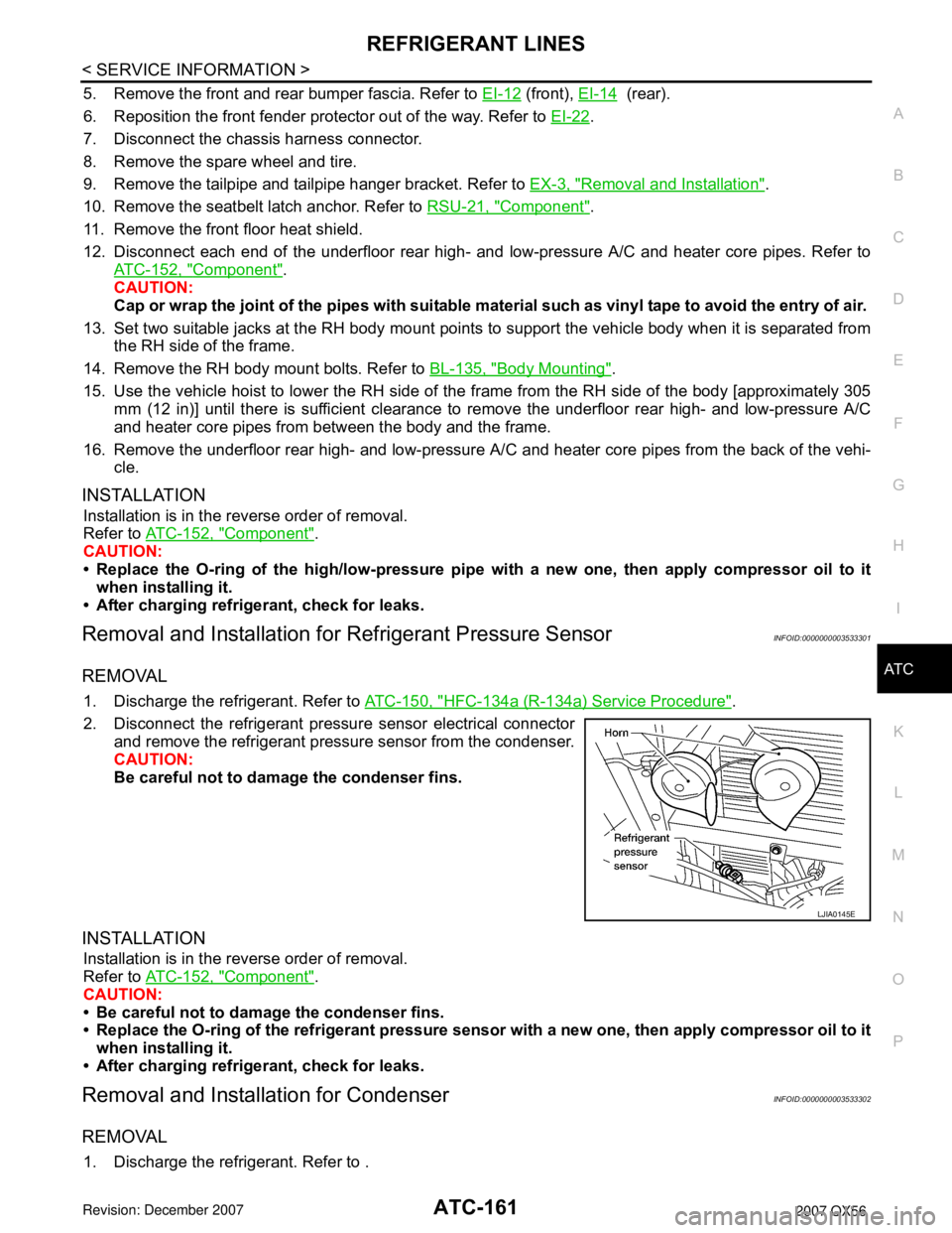
2. Disconnect the refrigerant pressu re sensor electrical connector
and remove the refrigerant pressure sensor from the condenser.
CAUTION:
Be careful not to damage the condenser fins.
INSTALLATION
Installation is in the reverse order of removal.
Refer to ATC-152, "
Component".
CAUTION:
• Be careful not to damage the condenser fins.
• Replace the O-ring of the refrig erant pressure sensor with a new one, then apply compressor oil to it
when installing it.
• After charging refrigerant, check for leaks.
Removal and Installation for CondenserINFOID:0000000003533302
REMOVAL
1. Discharge the refrigerant. Refer to .
LJIA0145E
Page 638 of 3061

AV-98
< SERVICE INFORMATION >
NAVIGATION SYSTEM
DIAGNOSIS ITEM
NOTE:
Make the status that is set by D/N function be shown.
Self-Diagnosis Mode (DCU)INFOID:0000000003533719
OPERATION PROCEDURE
1. Start the engine.
2. Turn the audio system off.
Mode Description
Self-diagnosis (DCU) Display control unit diagnosis.
Self-diagnosis (NAVI)• NAVI Control unit diagnosis (DVD-ROM drive) will not be diagnosed
when no map DVD-ROM is in it.
• Analyzes connection between the NAVI control unit and the GPS anten-
na and operation of each unit.
CONFIRMATION/
ADJUSTMENTDisplay diagnosisIn display control unit mode, color tone and shading of the screen can be
checked by the display of a color bar and a gray scale.
Vehicle signalsIn display control unit mode, analyzes the following vehicle signals: Vehicle
speed signal, light signal
NOTE, ignition switch signal, and reverse signal.
Auto Climate Control A/C self-diagnosis of A/C system.
NavigationDisplay diagnosisIn NAVI C/U mode, color tone and shading of the screen can be checked
by the display of a color bar and a gray scale.
Vehicle signalsIn NAVI C/U mode, analyzes the following vehicle signals: Vehicle speed
signal, light signal, ignition switch signal, and reverse signal.
History of ErrorsDiagnosis results previously stored in the memory (before turning ignition
switch ON) are displayed in this mode. Time and location when/where the
errors occurred are also displayed.
Naviga-
tionDisplay Lon-
gitude & Lat-
itudeDisplay the map. Use the joystick to adjust position. Longitude and latitude
will be displayed.
Speed Cali-
brationUnder ordinary conditions, the navigation system distance measuring func-
tion will automatically compensate for minute decreases in wheel and tire
diameter caused by tire wear or low-pressure. Speed calibration immedi-
ately restores system accuracy in cases such as when distance calibration
is needed because of the use of tire chains in inclement weather.
Angle ad-
justmentCorrects difference between actual turning angle of a vehicle and turning
angle of the car mark on the display.
Initialize Lo-
cationThis mode is for initializing the current location. Use when the vehicle is
transported a long distance on a trailer, etc.
CAN DIAG SUPPORT MONITOR Display status of CAN communication.
Page 649 of 3061

NAVIGATION SYSTEM
AV-109
< SERVICE INFORMATION >
C
D
E
F
G
H
I
J
L
MA
B
AV
N
O
P
• During normal driving, distance error caused by tire wear and tire
pressure change is automatically adjusted for by the automatic dis-
tance correction function. This function, on the other hand, is for
immediate adjustment, in cases such as driving with tire chain fit-
ted on tires.
CAN Diagnostic Support MonitorINFOID:0000000003533722
OPERATION PROCEDURE
1. Start the engine.
2. Turn the audio system off.
3. While pressing the “MEMORY 4” button, turn the volume control
dial clockwise or counterclockwise for 30 clicks or more. (When
the self-diagnosis mode is started, a short beep will be heard.)
• Shifting from current screen to previous screen is performed
by pressing “BACK” button.
4. The initial self-diagnosis screen will be shown, and items “Self-
Diagnosis (DCU)”, “Self-Diagnosis (NAVI)”, “Confirmation/
Adjustment” and “CAN DIAG SUPPORT MONITOR” will
become selective.
5. Select “CAN DIAG SUPPORT MONITOR”.
WKIA4315E
WKIA4439E
SKIA4207E
Page 694 of 3061

BCM (BODY CONTROL MODULE)
BCS-7
< SERVICE INFORMATION >
C
D
E
F
G
H
I
J
L
MA
B
BCS
N
O
P
CAN Communication System DescriptionINFOID:0000000003533597
Refer to LAN-4.
Headlamp Combination switch IPDM E/R
Tail lamp Combination switch IPDM E/R
Front fog lamp Combination switch IPDM E/R
Turn signal lamp Combination switch• Turn signal lamp
• Combination meter
Hazard lamp Hazard switch• Turn signal lamp
• Combination meter
Room lamp timer• Key switch
• Remote keyless entry receiver (keyfob)
• Main power window and door lock/unlock switch
• Front door lock assembly LH (key cylinder switch)
• All door switchesInterior room lamp
Key warning chime• Key switch
• Front door switch LHCombination meter (warning buzz-
er)
Light warning chime• Combination switch
• Key switch
• Front door switch LHCombination meter (warning buzz-
er)
Vehicle-speed-sensing intermittent wip-
er• Combination switch
• Combination meterIPDM E/R
Rear window defogger Rear window defogger switch IPDM E/R
Air conditioner switch signal Front air control ECM
Blower fan switch signal Front air control ECM
Low tire pressure warning system Remote keyless entry receiver• Combination meter
• Display control unit
Trailer tow (if equipped) Combination switch Trailer turn signal relays
Vehicle security system• Remote keyless entry receiver (keyfob)
• Main power window and door lock/unlock switch
• Power window and door lock/unlock switch RH
• Front door lock assembly LH (key cylinder switch)
• All door switches
• Back door latch (door ajar switch)• IPDM E/R
• Security indicator lamp System Input Output
Page 698 of 3061

BCM (BODY CONTROL MODULE)
BCS-11
< SERVICE INFORMATION >
C
D
E
F
G
H
I
J
L
MA
B
BCS
N
O
P
Terminal and Reference Value for BCMINFOID:0000000003533600
Te r m i n a lWire
colorSignal nameSignal
input/
outputMeasuring condition
Reference value or waveform
(Approx.) Ignition
switchOperation or condition
1BR/WIgnition keyhole illumi-
nationOutput OFFDoor is locked (SW OFF) Battery voltage
Door is unlocked (SW ON) 0V
2SBCombination switch
input 5Input ONLighting, turn, wiper OFF
Wiper dial position 4
3G/YCombination switch
input 4Input ONLighting, turn, wiper OFF
Wiper dial position 4
4YCombination switch
input 3Input ONLighting, turn, wiper OFF
Wiper dial position 4
5G/BCombination switch
input 2
Input ONLighting, turn, wiper OFF
Wiper dial position 4
6VCombination switch
input 1
9Y/BRear window defogger
switchInput ONRear window defogger switch
ON0V
Rear window defogger switch
OFF5V
10 G Hazard lamp flash Input OFFON (opening or closing) 0V
OFF (other than above) Battery voltage
11 OIgnition switch (ACC
or ON)InputACC or
ONIgnition switch ACC or ON Battery voltage
12 R/L Front door switch RH Input OFFON (open) 0V
OFF (closed) Battery voltage
13 GR Rear door switch RH Input OFFON (open) 0V
OFF (closed) Battery voltage
15 L/WTire pressure warning
check connectorInput OFF — 5V
SKIA5291E
SKIA5292E
SKIA5291E
SKIA5292E
Page 704 of 3061

BCM (BODY CONTROL MODULE)
BCS-17
< SERVICE INFORMATION >
C
D
E
F
G
H
I
J
L
MA
B
BCS
N
O
P
CONSULT-II START PROCEDURE
Refer to GI-36, "CONSULT-II Start Procedure".
ITEMS OF EACH PART
NOTE:
CONSULT-II will only display systems the vehicle possesses.
WORK SUPPORT
BCM diagnostic
test itemDiagnostic mode Content
Inspection by partWORK SUPPORTSupports inspections and adjustments. Commands are transmitted to the BCM for
setting the status suitable for required operation, input/output signals are received
from the BCM and received data is displayed.
DATA MONITOR Displays BCM input/output data in real time.
ACTIVE TEST Operation of electrical loads can be checked by sending drive signal to them.
SELF-DIAG RESULTS Displays BCM self-diagnosis results.
CAN DIAG SUPPORT
MNTRThe results of transmit/receive diagnosis of CAN communication can be read.
ECU PART NUMBER BCM part number can be read.
CONFIGURATION Performs BCM configuration read/write functions.
System and itemCONSULT-II
displayDiagnostic test mode (Inspection by part)
WORK
SUPPORTSELF−
DIAG RE-
SULTSCAN DIAG
SUPPORT
MNTRDATA
MONITORECU
PA R T
NUMBERAC-
TIVE
TESTCON-
FIGU-
RATION
BCM BCM×× × × ×
Power door lock system DOOR LOCK×××
Rear defoggerREAR
DEFOGGER××
Warning chime BUZZER××
Room lamp timer INT LAMP×××
Remote keyless entry
systemMULTI REMOTE
ENT×××
Headlamp HEAD LAMP×××
Wiper (front/rear) WIPER×××
Turn signal lamp
Hazard lampFLASHER××
Blower fan switch signal
Air conditioner switch
signalAIR
CONDITIONER×
Combination switch COMB SW×
IVIS (NATS) IMMU××
Interior lamp battery
saverBATTERY SAV-
ER×××
Back door TRUNK××
Theft alarm THEFT ALM×××
Retained accessory
power controlRETAINED PWR×××
Oil pressure switch SIGNAL BUFFER××
Low tire pressure moni-
tor systemAIR PRESSURE
MONITOR×× × ×
Panic alarm PANIC ALARM×