lock INFINITI QX56 2007 Factory Service Manual
[x] Cancel search | Manufacturer: INFINITI, Model Year: 2007, Model line: QX56, Model: INFINITI QX56 2007Pages: 3061, PDF Size: 64.56 MB
Page 1858 of 3061
EM-88
< SERVICE INFORMATION >
CYLINDER BLOCK
Unit: mm (in)
NOTE:
• The piston is available together with piston pin as an assembly.
• The piston pin (piston pin bore) grade is provided only for the parts installed at the plant. For service parts,
grades can be selected.
• Hone the cylinder to obtain specified clearance between the piston and cylinder bore.
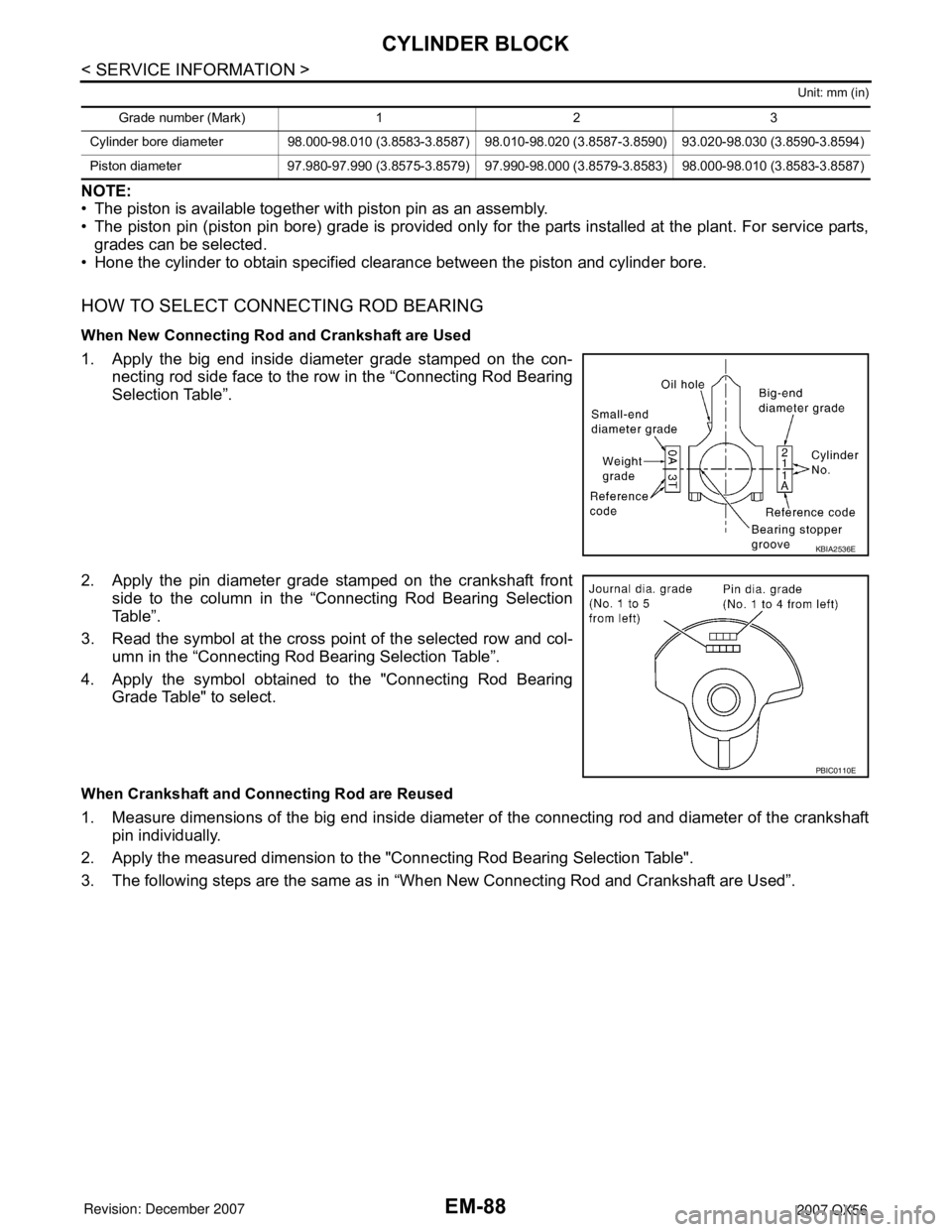
HOW TO SELECT CONNECTING ROD BEARING
When New Connecting Rod and Crankshaft are Used
1. Apply the big end inside diameter grade stamped on the con-
necting rod side face to the row in the “Connecting Rod Bearing
Selection Table”.
2. Apply the pin diameter grade stamped on the crankshaft front
side to the column in the “Connecting Rod Bearing Selection
Table”.
3. Read the symbol at the cross point of the selected row and col-
umn in the “Connecting Rod Bearing Selection Table”.
4. Apply the symbol obtained to the "Connecting Rod Bearing
Grade Table" to select.
When Crankshaft and Connecting Rod are Reused
1. Measure dimensions of the big end inside diameter of the connecting rod and diameter of the crankshaft
pin individually.
2. Apply the measured dimension to the "Connecting Rod Bearing Selection Table".
3. The following steps are the same as in “When New Connecting Rod and Crankshaft are Used”.
Grade number (Mark) 1 2 3
Cylinder bore diameter 98.000-98.010 (3.8583-3.8587) 98.010-98.020 (3.8587-3.8590) 93.020-98.030 (3.8590-3.8594)
Piston diameter 97.980-97.990 (3.8575-3.8579) 97.990-98.000 (3.8579-3.8583) 98.000-98.010 (3.8583-3.8587)
KBIA2536E
PBIC0110E
Page 1859 of 3061
CYLINDER BLOCK
EM-89
< SERVICE INFORMATION >
C
D
E
F
G
H
I
J
K
L
MA
EM
N
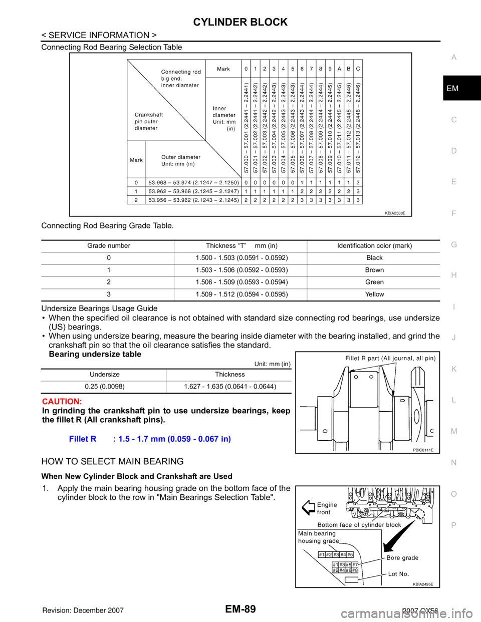
P O Connecting Rod Bearing Selection Table
Connecting Rod Bearing Grade Table.
Undersize Bearings Usage Guide
• When the specified oil clearance is not obtained with standard size connecting rod bearings, use undersize
(US) bearings.
• When using undersize bearing, measure the bearing inside diameter with the bearing installed, and grind the
crankshaft pin so that the oil clearance satisfies the standard.
Bearing undersize table
Unit: mm (in)
CAUTION:
In grinding the crankshaft pin to use undersize bearings, keep
the fillet R (All crankshaft pins).
HOW TO SELECT MAIN BEARING
When New Cylinder Block and Crankshaft are Used
1. Apply the main bearing housing grade on the bottom face of the
cylinder block to the row in "Main Bearings Selection Table".
KBIA2538E
Grade number Thickness “T” mm (in) Identification color (mark)
0 1.500 - 1.503 (0.0591 - 0.0592) Black
1 1.503 - 1.506 (0.0592 - 0.0593) Brown
2 1.506 - 1.509 (0.0593 - 0.0594) Green
3 1.509 - 1.512 (0.0594 - 0.0595) Yellow
Undersize Thickness
0.25 (0.0098) 1.627 - 1.635 (0.0641 - 0.0644)
Fillet R : 1.5 - 1.7 mm (0.059 - 0.067 in)
PBIC0111E
KBIA2495E
Page 1860 of 3061
EM-90
< SERVICE INFORMATION >
CYLINDER BLOCK
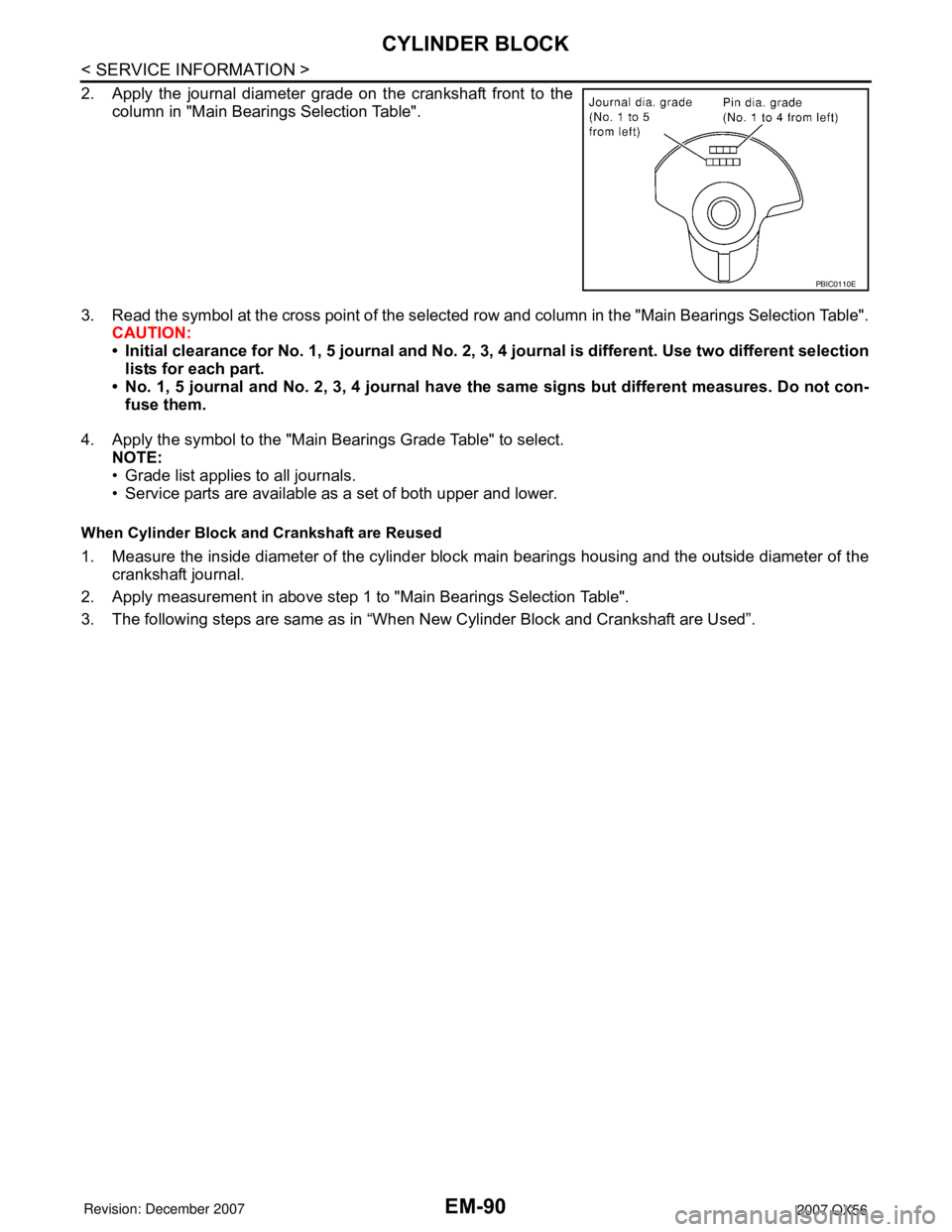
2. Apply the journal diameter grade on the crankshaft front to the
column in "Main Bearings Selection Table".
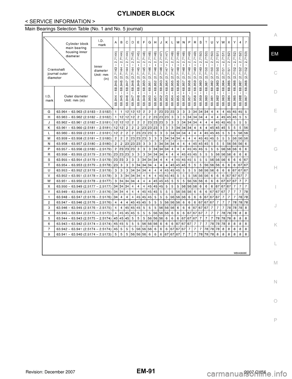
3. Read the symbol at the cross point of the selected row and column in the "Main Bearings Selection Table".
CAUTION:
• Initial clearance for No. 1, 5 journal and No. 2, 3, 4 journal is different. Use two different selection
lists for each part.
• No. 1, 5 journal and No. 2, 3, 4 journal have the same signs but different measures. Do not con-
fuse them.
4. Apply the symbol to the "Main Bearings Grade Table" to select.
NOTE:
• Grade list applies to all journals.
• Service parts are available as a set of both upper and lower.
When Cylinder Block and Crankshaft are Reused
1. Measure the inside diameter of the cylinder block main bearings housing and the outside diameter of the
crankshaft journal.
2. Apply measurement in above step 1 to "Main Bearings Selection Table".
3. The following steps are same as in “When New Cylinder Block and Crankshaft are Used”.
PBIC0110E
Page 1861 of 3061
CYLINDER BLOCK
EM-91
< SERVICE INFORMATION >
C
D
E
F
G
H
I
J
K
L
MA
EM
N
P O Main Bearings Selection Table (No. 1 and No. 5 journal)
WBIA0608E
Page 1862 of 3061
EM-92
< SERVICE INFORMATION >
CYLINDER BLOCK
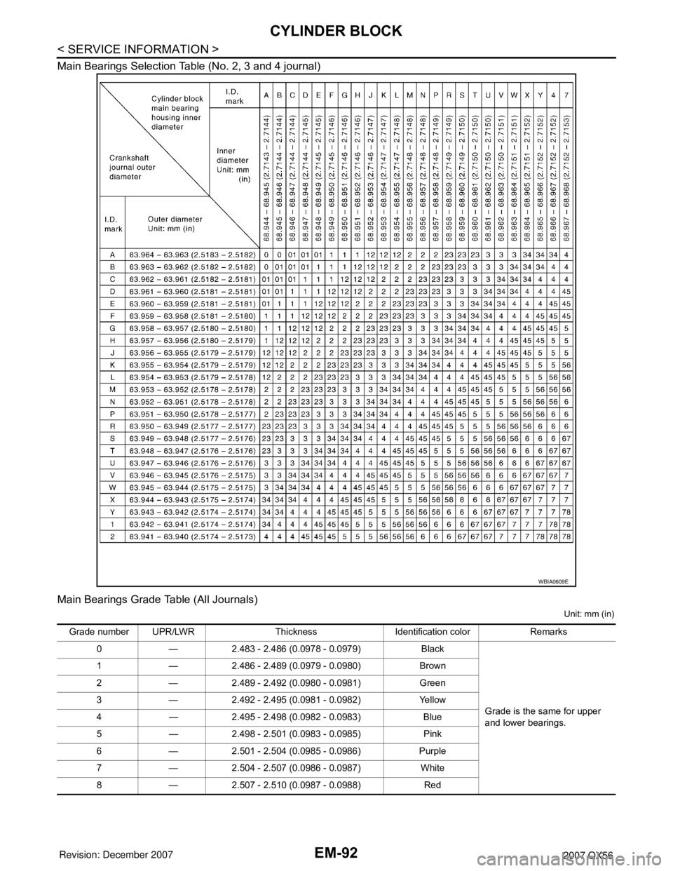
Main Bearings Selection Table (No. 2, 3 and 4 journal)
Main Bearings Grade Table (All Journals)
Unit: mm (in)
WBIA0609E
Grade number UPR/LWR Thickness Identification color Remarks
0 — 2.483 - 2.486 (0.0978 - 0.0979) Black
Grade is the same for upper
and lower bearings. 1 — 2.486 - 2.489 (0.0979 - 0.0980) Brown
2 — 2.489 - 2.492 (0.0980 - 0.0981) Green
3 — 2.492 - 2.495 (0.0981 - 0.0982) Yellow
4 — 2.495 - 2.498 (0.0982 - 0.0983) Blue
5 — 2.498 - 2.501 (0.0983 - 0.0985) Pink
6 — 2.501 - 2.504 (0.0985 - 0.0986) Purple
7 — 2.504 - 2.507 (0.0986 - 0.0987) White
8 — 2.507 - 2.510 (0.0987 - 0.0988) Red
Page 1863 of 3061
CYLINDER BLOCK
EM-93
< SERVICE INFORMATION >
C
D
E
F
G
H
I
J
K
L
MA
EM
N
P O Use Undersize Bearing Usage Guide
• Use undersize (US) bearing when the oil clearance with standard size main bearing is not within specifica-
tion.
• When using undersize (US) bearing, measure the inside diameter of the bearing installed and grind the jour-
nal until the oil clearance falls within specification.
Bearing undersize table
Unit: mm (in)
CAUTION:
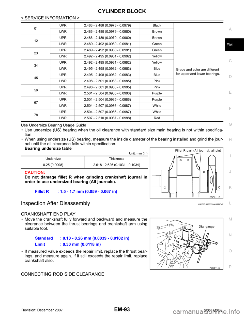
Do not damage fillet R when grinding crankshaft journal in
order to use undersized bearing (All journals).
Inspection After DisassemblyINFOID:0000000003531547
CRANKSHAFT END PLAY
• Move the crankshaft fully forward and backward and measure the
clearance between the thrust bearings and crankshaft arm using
suitable tool.
• If measured value exceeds the repair limit, replace the thrust bear-
ings, and measure again. If it still exceeds the repair limit, replace
crankshaft also.
CONNECTING ROD SIDE CLEARANCE
01UPR 2.483 - 2.486 (0.0978 - 0.0979) Black
Grade and color are different
for upper and lower bearings. LWR 2.486 - 2.489 (0.0979 - 0.0980) Brown
12UPR 2.486 - 2.489 (0.0979 - 0.0980) Brown
LWR 2.489 - 2.492 (0.0980 - 0.0981) Green
23UPR 2.489 - 2.492 (0.0980 - 0.0981) Green
LWR 2.492 - 2.495 (0.0981 - 0.0982) Yellow
34UPR 2.492 - 2.495 (0.0981 - 0.0982) Yellow
LWR 2.495 - 2.498 (0.0982 - 0.0983) Blue
45UPR 2.495 - 2.498 (0.0982 - 0.0983) Blue
LWR 2.498 - 2.501 (0.0983 - 0.0985) Pink
56UPR 2.498 - 2.501 (0.0983 - 0.0985) Pink
LWR 2.501 - 2.504 (0.0985 - 0.0986) Purple
67UPR 2.501 - 2.504 (0.0985 - 0.0986) Purple
LWR 2.504 - 2.507 (0.0986 - 0.0987) White
78UPR 2.504 - 2.507 (0.0986 - 0.0987) White
LWR 2.507 - 2.510 (0.0987 - 0.0988) Red
Undersize Thickness
0.25 (0.0098) 2.618 - 2.626 (0.1031 - 0.1034)
Fillet R : 1.5 - 1.7 mm (0.059 - 0.067 in)
PBIC0111E
Standard : 0.10 - 0.26 mm (0.0039 - 0.0102 in)
Limit : 0.30 mm (0.0118 in)
PBIC0114E
Page 1864 of 3061
EM-94
< SERVICE INFORMATION >
CYLINDER BLOCK
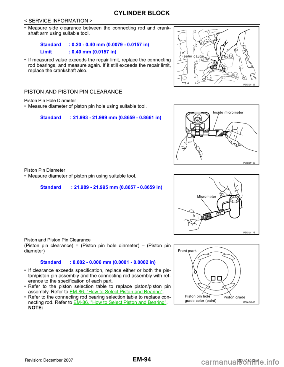
• Measure side clearance between the connecting rod and crank-
shaft arm using suitable tool.
• If measured value exceeds the repair limit, replace the connecting
rod bearings, and measure again. If it still exceeds the repair limit,
replace the crankshaft also.
PISTON AND PISTON PIN CLEARANCE
Piston Pin Hole Diameter
• Measure diameter of piston pin hole using suitable tool.
Piston Pin Diameter
• Measure diameter of piston pin using suitable tool.
Piston and Piston Pin Clearance
(Piston pin clearance) = (Piston pin hole diameter) – (Piston pin
diameter)
• If clearance exceeds specification, replace either or both the pis-
ton/piston pin assembly and the connecting rod assembly with ref-
erence to the specification of each part.
• Refer to the piston selection table to replace piston/piston pin
assembly. Refer to EM-86, "
How to Select Piston and Bearing".
• Refer to the connecting rod bearing selection table to replace con-
necting rod. Refer to EM-86, "
How to Select Piston and Bearing".
NOTE:Standard : 0.20 - 0.40 mm (0.0079 - 0.0157 in)
Limit : 0.40 mm (0.0157 in)
PBIC0115E
Standard : 21.993 - 21.999 mm (0.8659 - 0.8661 in)
PBIC0116E
Standard : 21.989 - 21.995 mm (0.8657 - 0.8659 in)
PBIC0117E
Standard : 0.002 - 0.006 mm (0.0001 - 0.0002 in)
KBIA2496E
Page 1865 of 3061
CYLINDER BLOCK
EM-95
< SERVICE INFORMATION >
C
D
E
F
G
H
I
J
K
L
MA
EM
N
P O
The connecting rod small end grade and piston pin hole (piston
pin) grade are provided only for the parts installed at the plant. For
service parts, no grades can be selected (only 0 grade is avail-
able).
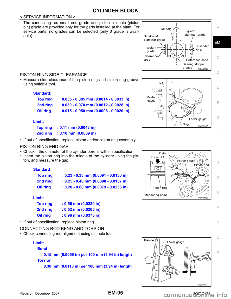
PISTON RING SIDE CLEARANCE
• Measure side clearance of the piston ring and piston ring groove
using suitable tool.
• If out of specification, replace piston and/or piston ring assembly.
PISTON RING END GAP
• Check if the diameter of the cylinder bore is within specification.
• Insert the piston ring into the middle of the cylinder using the pis-
ton, and measure the gap.
• If out of specification, replace piston ring.
CONNECTING ROD BEND AND TORSION
• Check connecting rod alignment using suitable tool.
KBIA2536E
Standard:
Top ring : 0.035 - 0.085 mm (0.0014 - 0.0033 in)
2nd ring : 0.030 - 0.070 mm (0.0012 - 0.0028 in)
Oil ring : 0.015 - 0.050 mm (0.0006 - 0.0020 in)
Limit:
Top ring : 0.11 mm (0.0043 in)
2nd ring : 0.10 mm (0.0039 in)
SEM024AA
Standard
Top ring : 0.23 - 0.33 mm (0.0091 - 0.0130 in)
2nd ring : 0.25 - 0.40 mm (0.0098 - 0.0157 in)
Oil ring : 0.20 - 0.60 mm (0.0079 - 0.0236 in)
Limit:
Top ring : 0.56 mm (0.0220 in)
2nd ring : 0.52 mm (0.0205 in)
Oil ring : 0.96 mm (0.0378 in)
PBIC0118E
Limit:
Bend
: 0.15 mm (0.0059 in) per 100 mm (3.94 in) length
To r s i o n
: 0.30 mm (0.0118 in) per 100 mm (3.94 in) length
SEM003F
Page 1866 of 3061

EM-96
< SERVICE INFORMATION >
CYLINDER BLOCK
• If measurement exceeds the limit, replace connecting rod assem-
bly.
CONNECTING ROD BEARING (BIG END)
• Install the connecting rod cap without the connecting rod bearing
installed. After tightening the connecting rod bolt to the specified
torque, measure the connecting rod large end inside diameter.
Refer to EM-78, "
Disassembly and Assembly".
• If measurement exceeds the standard, replace connecting rod.
CONNECTING ROD BUSHING OIL CLEARANCE (SMALL END)
Connecting Rod Inside Diameter (Small End)
• Measure inside diameter of bushing using suitable tool.
Piston Pin Diameter
• Measure diameter of piston pin using suitable tool.
Connecting Rod Bushing Oil Clearance (Small End)
SEM038F
Standard : 57.000 - 57.013 mm (2.2441 - 2.2446 in)
PBIC1641E
Standard : 22.000 - 22.006 mm (0.8661 - 0.8664 in)
PBIC0120E
Standard : 21.989 - 21.995 mm (0.8657 - 0.8659 in)
PBIC0117E
Page 1867 of 3061

CYLINDER BLOCK
EM-97
< SERVICE INFORMATION >
C
D
E
F
G
H
I
J
K
L
MA
EM
N
P O
(Connecting rod small end oil clearance) = (Inside diameter of con-
necting rod small end) – (Piston pin diameter)
• If measured value exceeds the standard, replace the connecting
rod assembly and/or piston and piston pin assembly.
• If replacing the piston and piston pin assembly, refer to the Table
for Selective Fitting for Piston to select the piston corresponding to
the applicable bore grade of the cylinder block to be used. Refer to
EM-86, "
How to Select Piston and Bearing".
Factory installed parts grading:
• Only grade 0 is available.
Unit: mm (in)
CYLINDER BLOCK DISTORTION
• Remove any oil, scale, gasket, sealant and carbon deposits from the cylinder block surface.
CAUTION:
Do not allow any debris to enter the oil or coolant passages.
• Measure block upper face for distortion in six directions as shown.
• If measurement exceeds the limit, replace cylinder block.
MAIN BEARING HOUSING INSIDE DIAMETER
• Install the main bearing caps with the main bearings removed, and
tighten the bolts to the specified torque. Refer to EM-78, "
Disas-
sembly and Assembly".
• Measure inside diameter of main bearing housing.
• If out of the standard, replace cylinder block and main bearing
caps as an assembly.
NOTE:
These components must be replaced as a single unit, because
they were processed together.
PISTON TO CYLINDER BORE CLEARANCE
Cylinder Bore Diameter
Standard : 0.005 - 0.017 mm (0.0002 - 0.0007 in)
KBIA2536E
Grade 0
Connecting rod bushing inside diameter22.000 - 22.006
(0.8661 - 0.8664)
Piston pin diameter21.989 - 21.995
(0.8657 - 0.8659)
Piston pin hole diameter21.993 - 21.999
(0.8659 - 0.8661)
KBIA2496E
Standard : 0.03 mm (0.0012 in)
Limit : 0.1 mm (0.004 in)
SEM123C
Standard : 68.944 - 68.968 mm (2.7143 - 2.7153 in)
PBIC1643E