brake rotor INFINITI QX56 2007 Factory Owner's Manual
[x] Cancel search | Manufacturer: INFINITI, Model Year: 2007, Model line: QX56, Model: INFINITI QX56 2007Pages: 3061, PDF Size: 64.56 MB
Page 2369 of 3061

PERIODIC MAINTENANCE
MA-7
< SERVICE INFORMATION >
C
D
E
F
G
H
I
J
K
MA
B
MA
N
O
P
(1) After 60,000 miles (96,000 km) or 48 months, inspect every 15,000 miles (24,000 km) or 12 months. Replace drive belts if damaged.
(2) If operating mainly in dusty conditions, more frequent maintenance may be required.
(3) Maintenance-free item. For service procedures, go to the FL section.
(4) After 60,000 miles (96,000 km) or 48 months, replace every 30,000 miles (48,000 km) or 24 months.
(5) If valve noise increases, inspect valve clearance.
* Maintenance items and intervals with “*” are recommended by NISSAN for reliable vehicle operation. The owner need not perform
such maintenance in order to maintain the emission warranty or manufacturer recall liability. Other maintenance items and intervals are
required.
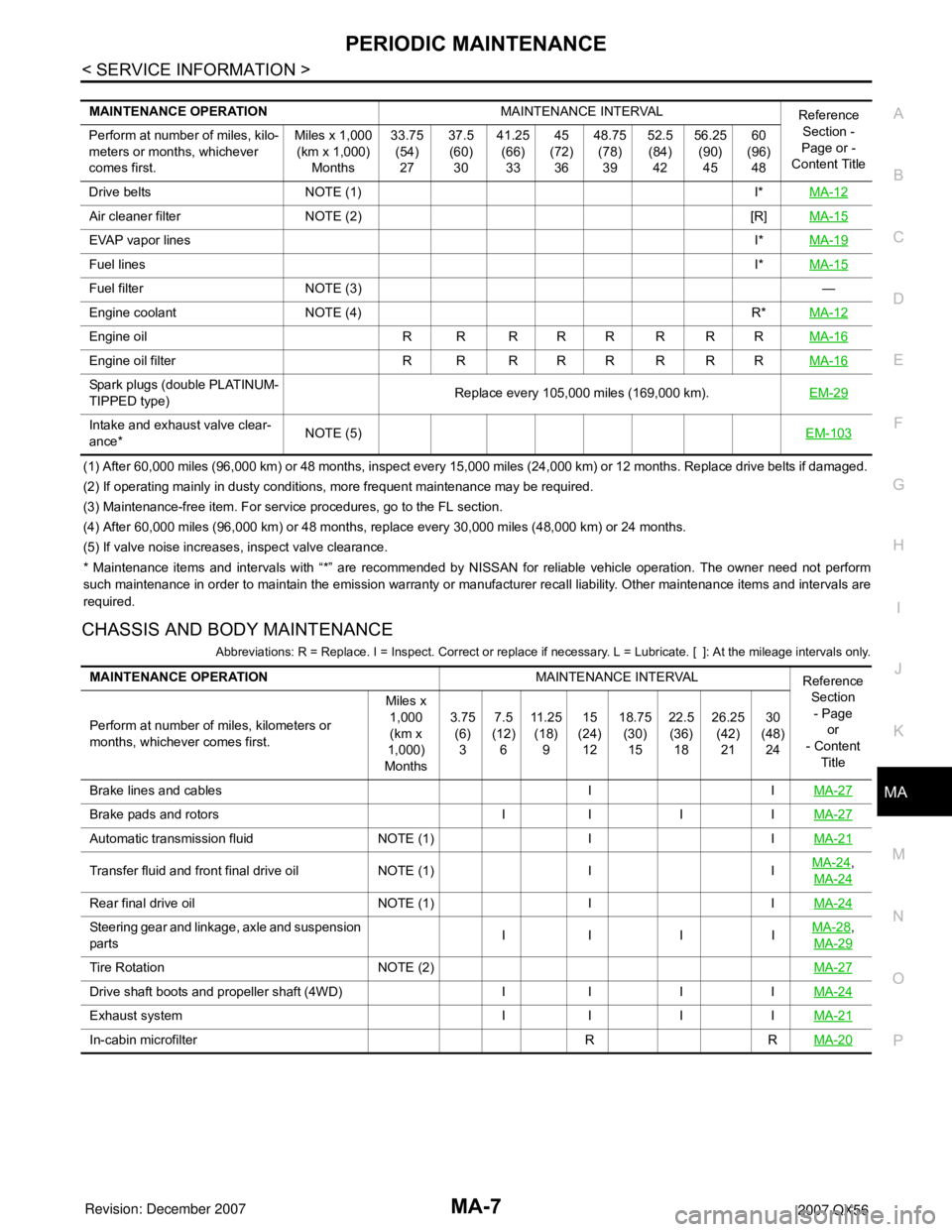
CHASSIS AND BODY MAINTENANCE
Abbreviations: R = Replace. I = Inspect. Correct or replace if necessary. L = Lubricate. [ ]: At the mileage intervals only.
MAINTENANCE OPERATIONMAINTENANCE INTERVAL
Reference
Section -
Page or -
Content Title Perform at number of miles, kilo-
meters or months, whichever
comes first.Miles x 1,000
(km x 1,000)
Months33.75
(54)
2737.5
(60)
3041.25
(66)
3345
(72)
3648.75
(78)
3952.5
(84)
4256.25
(90)
4560
(96)
48
Drive belts NOTE (1) I*MA-12
Air cleaner filter NOTE (2) [R]MA-15
EVAP vapor linesI*MA-19
Fuel linesI*MA-15
Fuel filter NOTE (3)—
Engine coolant NOTE (4) R*MA-12
Engine oil R R R R R R R RMA-16
Engine oil filter R R R R R R R RMA-16
Spark plugs (double PLATINUM-
TIPPED type)Replace every 105,000 miles (169,000 km).EM-29
Intake and exhaust valve clear-
ance*NOTE (5)EM-103
MAINTENANCE OPERATIONMAINTENANCE INTERVAL
Reference
Section
- Page
or
- Content
Title Perform at number of miles, kilometers or
months, whichever comes first.Miles x
1,000
(km x
1,000)
Months3.75
(6)
37.5
(12)
611 . 2 5
(18)
915
(24)
1218.75
(30)
1522.5
(36)
1826.25
(42)
2130
(48)
24
Brake lines and cables I IMA-27
Brake pads and rotors I I I IMA-27
Automatic transmission fluid NOTE (1) I IMA-21
Transfer fluid and front final drive oil NOTE (1) I IMA-24,
MA-24
Rear final drive oil NOTE (1) I IMA-24
Steering gear and linkage, axle and suspension
partsII I IMA-28,
MA-29
Tire Rotation NOTE (2)MA-27
Drive shaft boots and propeller shaft (4WD) I I I IMA-24
Exhaust system I I I IMA-21
In-cabin microfilter R RMA-20
Page 2370 of 3061

MA-8
< SERVICE INFORMATION >
PERIODIC MAINTENANCE
(1) If towing a trailer, or using a car-top carrier, or driving on rough or muddy roads, change (not just inspect) oil at every 30,000 miles
(48,000 km) or 24 months.
(2) Refer to “Tire rotation” under the “General maintenance” heading earlier in this section.
Schedule 2INFOID:0000000003533863
EMISSION CONTROL SYSTEM MAINTENANCE
Abbreviations: R = Replace. I = Inspect. Correct or replace if necessary. [ ]: At the mileage intervals only
(1) After 60,000 miles (96,000 km) or 48 months, inspect every 15,000 miles (24,000 km) or 12 months. Replace drive belts if damaged.
(2) Maintenance-free item. For service procedures, go to FL section.
(3) After 60,000 miles (96,000 km) or 48 months, replace every 30,000 miles (48,000 km) or 24 months.
(4) If valve noise increases, inspect valve clearance.
* Maintenance items and intervals with “*” are recommended by NISSAN for reliable vehicle operation. The owner need not perform
such maintenance in order to maintain the emission warranty or manufacturer recall liability. Other maintenance items and intervals are
required.
CHASSIS AND BODY MAINTENANCE
MAINTENANCE OPERATIONMAINTENANCE INTERVAL
Reference
Section
- Page
or
- Content
Title Perform at number of miles, kilometers or
months, whichever comes first.Miles x
1,000
(km x
1,000)
Months33.75
(54)
2737.5
(60)
3041.25
(66)
3345
(72)
3648.75
(78)
3952.5
(84)
4256.25
(90)
4560
(96)
48
Brake lines and cables I IMA-27
Brake pads and rotors I I I IMA-27
Automatic transmission fluid NOTE (1) I IMA-21
Transfer fluid and front final drive oil NOTE (1) I IMA-24,
MA-24
Rear final drive oil NOTE (1) I IMA-24
Steering gear and linkage, axle and suspen-
sion partsIIIIMA-28,
MA-29
Tire Rotation NOTE (2)MA-27
Drive shaft boots and propeller shaft (4WD) I I I IMA-24
Exhaust system I I I IMA-21
In-cabin microfilter R RMA-20
MAINTENANCE OPERATIONMAINTENANCE INTERVAL
Reference
Section - Page
or - Content Ti-
tle Perform at number of miles, kilometers
or months, whichever comes first.Miles x 1,000
(km x 1,000)
Months7.5
(12)
615
(24)
1222.5
(36)
1830
(48)
2437.5
(60)
3045
(72)
3652.5
(84)
4260
(96)
48
Drive belts NOTE (1) I*MA-12
Air cleaner filter [R] [R]MA-15
EVAP vapor lines I* I*MA-19
Fuel lines I* I*MA-15
Fuel filter NOTE (2) —
Engine coolant NOTE (3) R*MA-12
Engine oil R R R R R R R RMA-16
Engine oil filter R R R R R R R RMA-16
Spark plugs (PLATINUM-TIPPED
type)Replace every 105,000 miles (169,000 km).EM-29
Intake and exhaust valve clearance* NOTE (4)EM-103
Page 2371 of 3061
![INFINITI QX56 2007 Factory Owners Manual PERIODIC MAINTENANCE
MA-9
< SERVICE INFORMATION >
C
D
E
F
G
H
I
J
K
MA
B
MA
N
O
P
Abbreviations: R = Replace. I = Inspect. Correct or replace if necessary. L = Lubricate. [ ]: At the mileage interval INFINITI QX56 2007 Factory Owners Manual PERIODIC MAINTENANCE
MA-9
< SERVICE INFORMATION >
C
D
E
F
G
H
I
J
K
MA
B
MA
N
O
P
Abbreviations: R = Replace. I = Inspect. Correct or replace if necessary. L = Lubricate. [ ]: At the mileage interval](/img/42/57029/w960_57029-2370.png)
PERIODIC MAINTENANCE
MA-9
< SERVICE INFORMATION >
C
D
E
F
G
H
I
J
K
MA
B
MA
N
O
P
Abbreviations: R = Replace. I = Inspect. Correct or replace if necessary. L = Lubricate. [ ]: At the mileage interval only.
(1) Refer to “Tire rotation” under the “General maintenance” heading earlier in this section. MAINTENANCE OPERATIONMAINTENANCE INTERVAL Reference
Section
- Page
or
- Content
Title Perform at number of miles, kilometers or
months, whichever comes first.Miles x 1,000
(km x 1,000)
Months7.5
(12)
615
(24)
1222.5
(36)
1830
(48)
2437.5
(60)
3045
(72)
3652.
5
(84)
4260
(96)
48
Brake lines and cables I I I IMA-27
Brake pads and rotors I I I IMA-27
Automatic transmission fluid I I I IMA-21
Transfer fluid and front final drive oil I I I IMA-24,
MA-24
Rear final drive oil I I I IMA-24
Steering gear and linkage, axle and suspen-
sion partsIIMA-28,
MA-29
Tire rotation NOTE (1)MA-27
Drive shaft boots and propeller shaft
(4WD)IIIIMA-24
Exhaust system I IMA-21
In-cabin microfilter R R R RMA-20
Page 2389 of 3061

CHASSIS AND BODY MAINTENANCE
MA-27
< SERVICE INFORMATION >
C
D
E
F
G
H
I
J
K
MA
B
MA
N
O
P
5. Start wheel balancer. Make sure that inner and outer residual imbalance values are 5 g (0.18 oz) each or
below.
Wheel Balance (Maximum Allowable Imbalance)
• If either residual imbalance value exceeds 5 g (0.18 oz), repeat installation procedures.
Tire RotationINFOID:0000000003533885
1. Rotate the tires on each side from front to back as shown.
2. Adjust the tire pressure to specification. Refer to WT-28, "
Tire" .
3. After the tire rotation, retighten the wheel nuts after the vehicle
has been driven for 1,000 km (600 miles), and also after a wheel
and tire have been installed such as after repairing a flat tire.
Checking Brake Fluid Level and LeaksINFOID:0000000003533886
• Check the brake fluid level in the reservoir tank. It should be
between the “MAX” and “MIN” lines on the reservoir tank.
• If the fluid level is extremely low, check the brake system.
• If the brake warning lamp comes on when the fluid is at the correct
level, check the brake fluid level switch and the parking brake
switch.
CheckingBrake Line and CablesINFOID:0000000003533887
1. Check the brake lines and hoses for cracks, deterioration, and
other damage. Replace any damaged parts.
CAUTION:
If brake fluid leaks are visible around the brake line joints,
retighten the joint, or replace damaged parts as necessary.
2. Check for brake fluid leaks by fully depressing brake pedal while
engine is running.
Checking Disc BrakeINFOID:0000000003533888
ROTOR
Maximum allowable imbalanceDynamic (At rim flange) 5 g (0.18 oz) (one side)
Static 10 g (0.35 oz)
Wheel nuts : Refer to WT-6 .
AMA159
WFIA0173E
SBR389C
Page 2395 of 3061

PB-2
< SERVICE INFORMATION >
PREPARATION
SERVICE INFORMATION
PREPARATION
Commercial Service ToolINFOID:0000000003532754
The actual shapes of Kent-Moore tools may differ from those of special service tools illustrated here.
Tool number
(Kent-Moore No.)
Tool nameDescription
—
(J-21177-A)
Brake drum clearance gaugeMeasuring rear rotor drum to parking
brake shoe clearance
Power toolLoosening bolts and nuts
WFIA0167E
PBIC0190E
Page 2396 of 3061

PARKING BRAKE SYSTEM
PB-3
< SERVICE INFORMATION >
C
D
E
G
H
I
J
K
L
MA
B
PB
N
O
P
PARKING BRAKE SYSTEM
On-Vehicle ServiceINFOID:0000000003532755
PEDAL STROKE
• When parking brake pedal is operated with the specified force, make sure the stroke is within the specified
number of notches. Check by listening and counting the ratchet clicks.
INSPECTION
• Make sure the components are attached properly, checking for looseness or backlash.
• Check parking brake pedal assembly for bends, damage and cracks, and replace if necessary.
• Check cable for wear and damage, and replace if necessary.
• Check parking brake warning lamp switch for malfunction, and replace if necessary. Refer to DI-27, "
Wiring
Diagram - WARN -".
ADJUSTMENT
1. Remove the lower instrument panel LH. Refer to IP-10, "Removal and Installation" .
2. Partially engage parking brake pedal to access adjusting nut.
3. Insert a deep socket wrench to rotate adjusting nut and loosen
cable sufficiently. Then, disengage the parking brake pedal.
4. Remove the wheel and tire using power tool.
5. Remove the disc rotor and measure inner diameter at widest
point using Tool.
6. Transfer measurement less 0.6 mm to the parking brake shoes
and adjust accordingly.
7. Using wheel nuts, secure the disc to the hub to prevent it from
tilting.
8. Rotate the disc rotor to make sure there is no drag.
9. Adjust cable as follows:
a. Operate pedal 10 or more times with a force of 490 N (50 kg-f,
110 lb-f).
b. Rotate adjusting nut with deep socket to adjust pedal stroke to
specification.
c. With parking brake pedal completely disengaged, make sure
there is no drag on the parking brake.
10. Install the disc rotor.
11. Install the wheel and tire using power tool.
12. Install the lower instrument panel LH. Refer to IP-10, "
Removal and Installation" . Pedal stroke : 3 − 4 notches [under force of 196 N (20.0 kg-f, 44.1 lb-f)]
WFIA0165E
Tool number : — (J-21177-A)
Pedal stroke : 3 − 4 notches [under force of
196 N (20.0 kg-f, 44.1 lb-f)]
WFIA0166E
Page 2397 of 3061

PB-4
< SERVICE INFORMATION >
PARKING BRAKE CONTROL
PARKING BRAKE CONTROL
ComponentINFOID:0000000003532756
Removal and InstallationINFOID:0000000003532757
REMOVAL
1. Remove the lower instrument panel LH and center console. Refer to IP-10, "Removal and Installation"
and IP-10, "Removal and Installation" .
2. Remove the floor trim. Refer to EI-36
.
3. Disconnect the parking brake warning lamp switch.
4. Remove the adjusting nut.
CAUTION:
Do not reuse adjusting nut after removing it.
5. Remove the lock plate from the front cable.
6. Remove front cable bolts and nut.
7. Disconnect return spring from equalizer.
8. Disconnect the front cable from the equalizer and remove front cable.
9. Remove the rear disc rotors. Refer to BR-25, "
Removal and Installation of Brake Caliper and Disc Rotor" .
10. Remove shoes, and remove left and right rear cables from toggle levers. Refer to PB-6, "
Removal and
Installation" .
11. Remove equalizer from right and left rear cables.
1. Pedal assembly 2. Front cable 3. Right rear cable
4. Left rear cable 5. Return spring 6. Equalizer
7. Adjusting nut 8. Lock plate
WFIA0163E
Page 2399 of 3061

PB-6
< SERVICE INFORMATION >
PARKING BRAKE SHOE
PARKING BRAKE SHOE
Removal and InstallationINFOID:0000000003532758
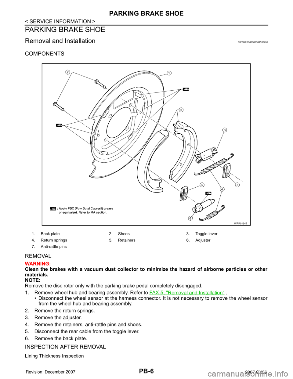
COMPONENTS
REMOVAL
WARNING:
Clean the brakes with a vacuum dust collector to minimize the hazard of airborne particles or other
materials.
NOTE:
Remove the disc rotor only with the parking brake pedal completely disengaged.
1. Remove wheel hub and bearing assembly. Refer to FA X - 5 , "
Removal and Installation" .
• Disconnect the wheel sensor at the harness connector. It is not necessary to remove the wheel sensor
from the wheel hub and bearing assembly.
2. Remove the return springs.
3. Remove the adjuster.
4. Remove the retainers, anti-rattle pins and shoes.
5. Disconnect the rear cable from the toggle lever.
6. Remove the back plate.
INSPECTION AFTER REMOVAL
Lining Thickness Inspection
1. Back plate 2. Shoes 3. Toggle lever
4. Return springs 5. Retainers 6. Adjuster
7. Anti-rattle pins
WFIA0164E
Page 2400 of 3061

PARKING BRAKE SHOE
PB-7
< SERVICE INFORMATION >
C
D
E
G
H
I
J
K
L
MA
B
PB
N
O
P
• Check thickness of lining.
Drum Inner Diameter Inspection
• Check drum inner diameter.
Other Inspections
• Check shoe sliding surface for excessive wear and damage.
• Check anti-rattle pins for excessive wear and corrosion.
• Check return springs for sagging.
• Check adjuster for rough operation.
• When disassembling adjuster, apply PBC (Poly Butyl Cuprysil) grease or equivalent to the adjuster threads.
Refer to MA-10
.
• Check either visually or with a vernier caliper to see if there is any excessive wear, cracks, or damage inside
drum.
INSTALLATION
Installation is in the reverse order of removal.
• Apply brake grease to the specified points during assembly. Refer to PB-4, "
Component" .
• Install adjuster so that threaded part expands when rotating it in
the direction shown by the arrow.
• Shorten adjuster by rotating it in the oposite direction as shown by
the arrow.
NOTE:
After replacing brake shoes or disc rotors, or if parking brake does
not function well, perform break-in operation as follows.
1. Adjust parking brake pedal stroke. Refer to PB-3, "
On-Vehicle
Service" .
2. Perform parking brake burnishing operation by driving the vehicle forward under the following conditions:
CAUTION:
• To prevent lining from getting too hot, allow a cool off period of approximately 5 minutes after
every break-in operation.Standard thickness "A" : 5.15 ± 0.25 mm
(0.203 ± 0.010 in)
Wear limit thickness "A" : 0.5 mm (0.020 in)
SBR021A
Standard inner diameter : 205 ± 0.13 mm
(8.07 ± 0.01 in)
Wear limit of inner diameter : 205.7 mm (8.10 in)
SBR768A
SFIA0153E
• Vehicle speed 40 km/h (25 mph) set (forward)
• Parking brake operating force 196 N (20.0 kg-f, 44.1 lb-f) set
• Apply time 30 sec.
Page 2523 of 3061

WHEEL HUB
RAX-5
< SERVICE INFORMATION >
C
E
F
G
H
I
J
K
L
MA
B
RAX
N
O
P
WHEEL HUB
On-Vehicle Inspection and ServiceINFOID:0000000003532624
Inspect the components for any looseness or back lash. Inspect each component for any excessive wear or
damage. Replace any components as necessary.
WHEEL BEARING INSPECTION
• Move the wheel hub and bearing assembly in the axial direction by hand to check the axial end play. Check
that the axial end play is with specification. Replace the wheel hub and bearing assembly as necessary.
• Rotate the wheel hub and bearing assembly to check that there are no unusual noises or other abnormal
conditions. Replace the wheel hub and bearing assembly as necessary.
Removal and InstallationINFOID:0000000003532625
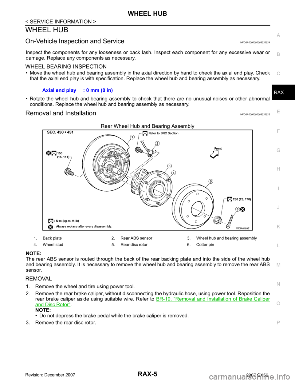
Rear Wheel Hub and Bearing Assembly
NOTE:
The rear ABS sensor is routed through the back of the rear backing plate and into the side of the wheel hub
and bearing assembly. It is necessary to remove the wheel hub and bearing assembly to remove the rear ABS
sensor.
REMOVAL
1. Remove the wheel and tire using power tool.
2. Remove the rear brake caliper, without disconnecting the hydraulic hose, using power tool. Reposition the
rear brake caliper aside using suitable wire. Refer to BR-19, "
Removal and Installation of Brake Caliper
and Disc Rotor".
NOTE:
• Do not depress the brake pedal while the brake caliper is removed.
3. Remove the rear disc rotor.Axial end play : 0 mm (0 in)
WDIA0189E
1. Back plate 2. Rear ABS sensor 3. Wheel hub and bearing assembly
4. Wheel stud 5. Rear disc rotor 6. Cotter pin