height INFINITI QX56 2007 Factory Service Manual
[x] Cancel search | Manufacturer: INFINITI, Model Year: 2007, Model line: QX56, Model: INFINITI QX56 2007Pages: 3061, PDF Size: 64.56 MB
Page 7 of 3061
2007
QUICK REFERENCE CHART: QX56
Disc Brake - Repair LimitsELS00293
Unit: mm (in)
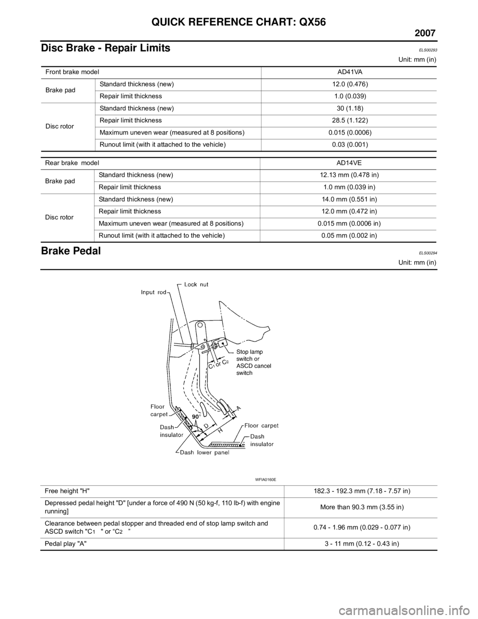
Brake PedalELS00294
Unit: mm (in)
Front brake model
AD41VA
Brake pad Standard thickness (new) 12.0 (0.476)
Repair limit thickness 1.0 (0.039)
Disc rotor Standard thickness (new) 30 (1.18)
Repair limit thickness 28.5 (1.122)
Maximum uneven wear (measured at 8 positions) 0.015 (0.0006)
Runout limit (with it attached to the vehicle) 0.03 (0.001)
Rear brake model
AD14VE
Brake pad Standard thickness (new) 12.13 mm (0.478 in)
Repair limit thickness 1.0 mm (0.039 in)
Disc rotor Standard thickness (new) 14.0 mm (0.551 in)
Repair limit thickness 12.0 mm (0.472 in)
Maximum uneven wear (measured at 8 positions) 0.015 mm (0.0006 in)
Runout limit (with it attached to the vehicle) 0.05 mm (0.002 in)
Free height "H"
182.3 - 192.3 mm (7.18 - 7.57 in)
Depressed pedal height "D" [under a force of 490 N (50 kg-f, 110 lb-f) with engine
running] More than 90.3 mm (3.55 in)
Clearance between pedal stopper and threaded end of stop lamp switch and
ASCD switch "C
1 " or “C2 ” 0.74 - 1.96 mm (0.029 - 0.077 in)
Pedal play "A" 3 - 11 mm (0.12 - 0.43 in)
WFIA0160E
Page 25 of 3061
![INFINITI QX56 2007 Factory Service Manual ACS-12
< SERVICE INFORMATION >[ICC]
LASER BEAM AIMING ADJUSTMENT
LASER BEAM AIMING ADJUSTMENT
Outline of Laser Beam Aiming Adjustment ProcedureINFOID:0000000003533782
CAUTION:
• The laser beam aimin INFINITI QX56 2007 Factory Service Manual ACS-12
< SERVICE INFORMATION >[ICC]
LASER BEAM AIMING ADJUSTMENT
LASER BEAM AIMING ADJUSTMENT
Outline of Laser Beam Aiming Adjustment ProcedureINFOID:0000000003533782
CAUTION:
• The laser beam aimin](/img/42/57029/w960_57029-24.png)
ACS-12
< SERVICE INFORMATION >[ICC]
LASER BEAM AIMING ADJUSTMENT
LASER BEAM AIMING ADJUSTMENT
Outline of Laser Beam Aiming Adjustment ProcedureINFOID:0000000003533782
CAUTION:
• The laser beam aiming adjustment cannot be performed without CONSULT-II.
• The laser beam aiming adjustment must be performed every time the ICC sensor is removed,
installed or has been moved as a result of a collision.
1. Prepare the vehicle and the work area.
2. Set up the ICC target board. For details, refer to Technical Service Bulletin.
3. Adjust the sensor following the procedure on CONSULT-II.
4. Check system operation after the adjustment.
PreparationINFOID:0000000003533783
• Place the vehicle on level ground. Shift the transmission into "P" position and release the parking brake.
• Adjust the tire pressure to the specified value.
• See that there is no load in the vehicle. Coolant, engine oil and fuel should be filled to correct level.
• Check that the vehicle suspension has been adjusted to the standard height by the load leveling rear air sus-
pension system. Refer to RSU-10, "
Basic Inspection" .
• Clean the sensor with a soft cloth.
Setting up the ICC Target BoardINFOID:0000000003533784
CAUTION:
Accuracy in setting up the ICC target board is essential for the laser beam aiming adjustment. For
details, refer to Technical Service Bulletin.
ADJUSTING HEIGHT OF THE TARGET
1. Attach a triangle scale as shown.Tool number : KV99110100 (J-45718)
LKIA0632E
WKIA1849E
Page 26 of 3061
![INFINITI QX56 2007 Factory Service Manual LASER BEAM AIMING ADJUSTMENT
ACS-13
< SERVICE INFORMATION >[ICC]
C
D
E
F
G
H
I
J
L
MA
B
ACS
N
O
P
2. Adjust the height of the target stand so that the point of the trian-
gle aims above the center of INFINITI QX56 2007 Factory Service Manual LASER BEAM AIMING ADJUSTMENT
ACS-13
< SERVICE INFORMATION >[ICC]
C
D
E
F
G
H
I
J
L
MA
B
ACS
N
O
P
2. Adjust the height of the target stand so that the point of the trian-
gle aims above the center of](/img/42/57029/w960_57029-25.png)
LASER BEAM AIMING ADJUSTMENT
ACS-13
< SERVICE INFORMATION >[ICC]
C
D
E
F
G
H
I
J
L
MA
B
ACS
N
O
P
2. Adjust the height of the target stand so that the point of the trian-
gle aims above the center of the ICC sensor.
ADJUSTING THE POSITION OF THE TARGET BOARD STRING
1. Attach a scale or straightedge (at least 350 mm [14 in] or
longer).
2. Suspend a string with a weight on the end 218 mm
(8.6 in) to the left side of the target board center.
POSITIONING THE TARGET
1. Suspend a string with weights on each end over the centerline of the vehicle. The string should lay over
the center of the front and back bumpers. Mark these centerpoints on the ground at each weight.
2. Connect the two center points using a string. Extend the string
an additional 5 m (16 ft) beyond the front centerpoint and mark
the floor. Position the target board weight on this mark.
3. Relocate the suspended string from the left side of the target board to the center of the target board. Mark
this point on the ground.
WKIA2039E
SKIA1211E
WKIA2040E
WKIA1851E
Page 283 of 3061

ON-VEHICLE SERVICE
AT-213
< SERVICE INFORMATION >
D
E
F
G
H
I
J
K
L
MA
B
AT
N
O
P
11. Remove bolts (A), (B) and (C) from control valve with TCM.
• : Front
12. Remove control valve with TCM from transmission case.
CAUTION:
Be careful with the manual valve notch and manual plate
height. Remove it vertically.
13. Remove A/T fluid temperature sensor 2 with bracket from con-
trol valve with TCM.
14. Remove bracket from A/T fluid temperature sensor 2.
15. Remove O-ring from A/T assembly harness connector.
Bolt symbol Length mm (in) Number of bolts
A 42 (1.65) 5
B 55 (2.17) 6
C 40 (1.57) 1
SCIA8074E
SCIA5142E
SCIA5253E
SCIA5264E
SCIA5155E
Page 317 of 3061

DISASSEMBLY
AT-247
< SERVICE INFORMATION >
D
E
F
G
H
I
J
K
L
MA
B
AT
N
O
P
34. Remove control valve with TCM from transmission case.
CAUTION:
When removing, be careful with transmission assembly ter-
minal connector and the manual valve notch and manual
plate height. Remove it vertically.
35. Remove A/T fluid temperature sensor 2 with bracket from con-
trol valve with TCM.
36. Remove bracket from A/T fluid temperature sensor 2.
37. Remove O-ring from A/T assembly harness connector.
38. Disconnect TCM connectors.
CAUTION:
Be careful not to damage connectors.
SCIA5308E
SCIA5253E
SCIA5264E
SCIA5155E
SCIA5447E
Page 614 of 3061

AV-74
< SERVICE INFORMATION >
NAVIGATION SYSTEM
Map-matching is a function that repositions the vehicle on the road
map when a new location is judged to be the most accurate. This is
done by comparing the current vehicle position, calculated by the
method described in the position detection principle, with the road
map data around the vehicle, read from the map DVD-ROM stored in
the DVD-ROM drive.
Therefore, the vehicle position may not be corrected after the vehicle
is driven over a certain distance or time in which GPS information is
hard to receive. In this case, the current-location mark on the display
must be corrected manually.
CAUTION:
The road map data is based on data stored in the map DVD-
ROM.
• In map-matching, alternative routes to reach the destination will be
shown and prioritized, after the road on which the vehicle is cur-
rently driven has been judged and the current-location mark has
been repositioned.
If there is an error in distance and/or direction, the alternative
routes will be shown in different order of priority, and the wrong
road can be avoided.
If two roads are running in parallel, they are of the same priority.
Therefore, the current-location mark may appear on either of them
alternately, depending on maneuvering of the steering wheel and
configuration of the road.
• Map-matching does not function correctly when the road on which
the vehicle is driving is new and not recorded in the map DVD-
ROM, or when the road pattern stored in the map data and the
actual road pattern are different due to repair.
When driving on a road not present in the map, the map-matching
function may find another road and position the current-location
mark on it. Then, when the correct road is detected, the current-
location mark may leap to it.
• Effective range for comparing the vehicle position and travel direc-
tion calculated by the distance and direction with the road data
read from the map DVD-ROM is limited. Therefore, when there is
an excessive gap between the current vehicle position and the
position on the map, correction by map-matching is not possible.
GPS (GLOBAL POSITIONING SYSTEM)
GPS (Global Positioning System) has been developed and con-
trolled by the US Department of Defense. The system utilizes GPS
satellite (NAVSTAR), sending out radio waves while flying on an orbit
around the earth at the height of approx. 21,000 km (13,000 miles).
The GPS receiver calculates the vehicle's position in three dimen-
sions (latitude/longitude/altitude) according to the time lag of the
radio waves received from four or more GPS satellites (three-dimen-
sional positioning). If radio waves were received only from three
GPS satellites, the GPS receiver calculates the vehicle's position in
two dimensions (latitude/longitude), utilizing the altitude data calcu-
lated previously by using radio waves from four or more GPS satel-
lites (two-dimensional positioning).
Accuracy of the GPS will deteriorate under the following conditions.
• In two-dimensional positioning, the GPS accuracy will deteriorate when the altitude of the vehicle position
changes.
• There may be an error of approximately 10 m (30 ft) in position detected by three-dimensional positioning,
which is more accurate than two-dimensional positioning. The accuracy can be even lower depending on the
arrangement of the GPS satellites utilized for the positioning.
• Position detection is not possible when the vehicle is in an area where radio waves from the GPS satellite do
not reach, such as in a tunnel, parking lot in a building, and under an elevated highway. Radio waves from
the GPS satellites may not be received when some object is located over the GPS antenna.
SEL685V
SEL686V
SKIA0613E
SEL526V
Page 722 of 3061
HOOD
BL-11
< SERVICE INFORMATION >
C
D
E
F
G
H
J
K
L
MA
B
BL
N
O
P
HOOD
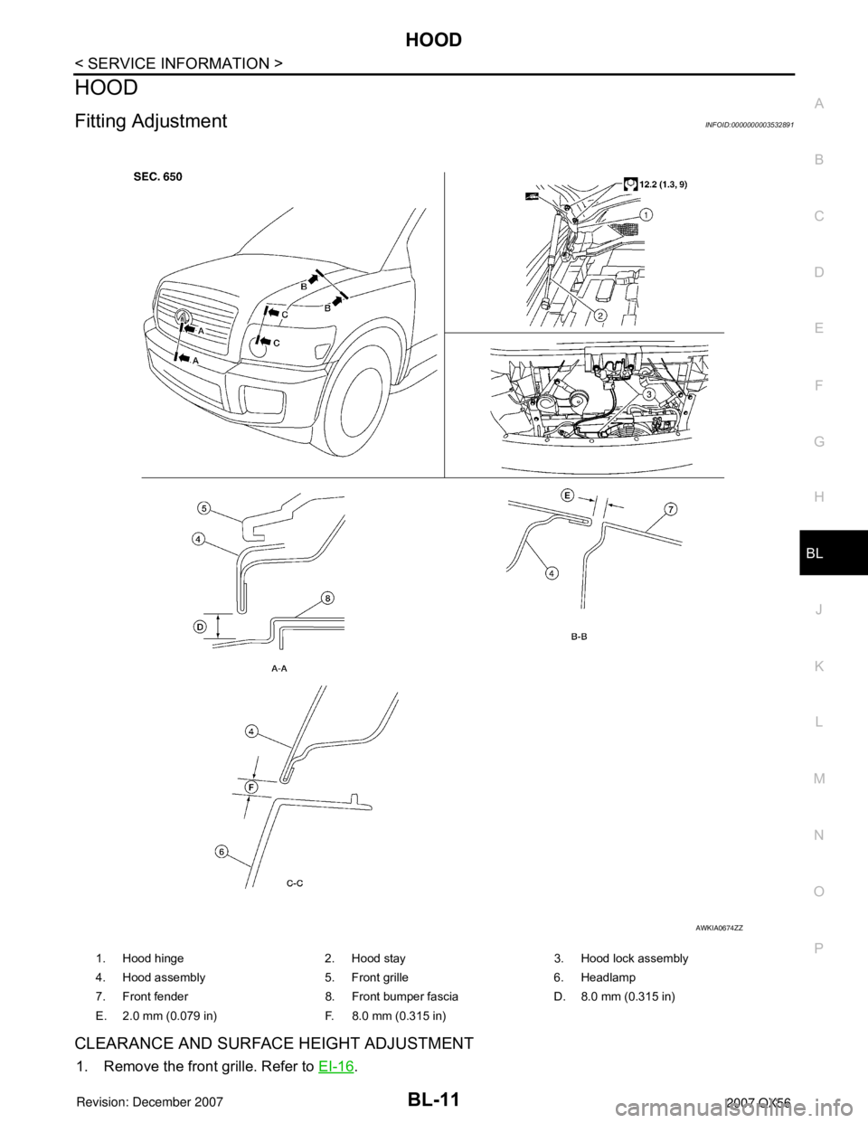
Fitting AdjustmentINFOID:0000000003532891
CLEARANCE AND SURFACE HEIGHT ADJUSTMENT
1. Remove the front grille. Refer to EI-16.
1. Hood hinge 2. Hood stay 3. Hood lock assembly
4. Hood assembly 5. Front grille 6. Headlamp
7. Front fender 8. Front bumper fascia D. 8.0 mm (0.315 in)
E. 2.0 mm (0.079 in) F. 8.0 mm (0.315 in)
AWKIA0674ZZ
Page 723 of 3061
BL-12
< SERVICE INFORMATION >
HOOD
2. Remove the hood lock assembly and adjust the height by rotating the bumper rubber until the hood clear-
ance of hood and fender becomes 1 mm (0.04 in) lower than fitting standard dimension.
3. Temporarily tighten the hood lock, and position it by engaging it with the hood striker. Check the lock and
striker for looseness, and tighten the lock mounting bolt to the specified torque.
4. Adjust the clearance and surface height of hood and fender according to the fitting standard dimension by
rotating right and left bumper rubbers.
CAUTION:
Adjust right/left gap between hood and each part to the following specification.
5. Install the front grille. Refer to EI-16
.
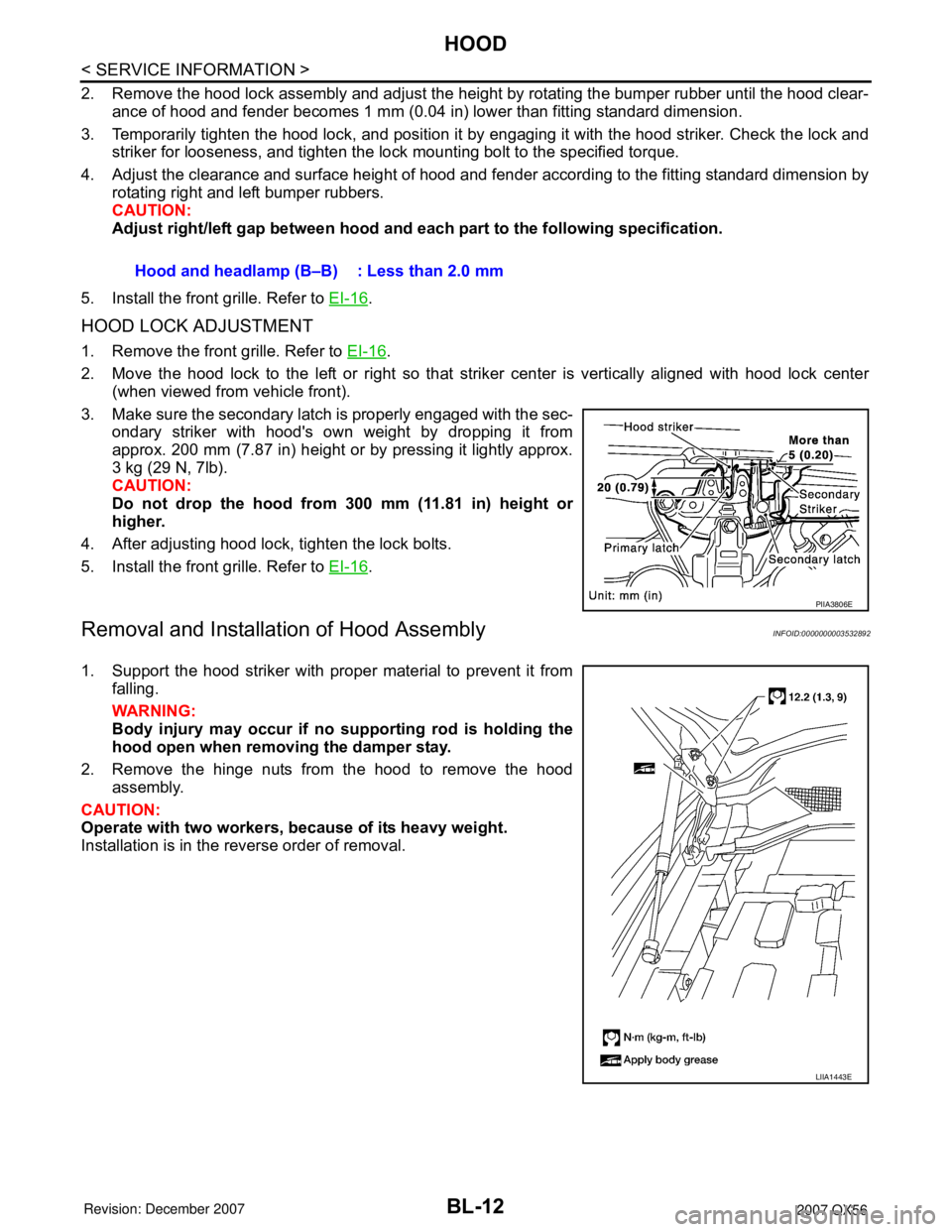
HOOD LOCK ADJUSTMENT
1. Remove the front grille. Refer to EI-16.
2. Move the hood lock to the left or right so that striker center is vertically aligned with hood lock center
(when viewed from vehicle front).
3. Make sure the secondary latch is properly engaged with the sec-
ondary striker with hood's own weight by dropping it from
approx. 200 mm (7.87 in) height or by pressing it lightly approx.
3 kg (29 N, 7lb).
CAUTION:
Do not drop the hood from 300 mm (11.81 in) height or
higher.
4. After adjusting hood lock, tighten the lock bolts.
5. Install the front grille. Refer to EI-16
.
Removal and Installation of Hood AssemblyINFOID:0000000003532892
1. Support the hood striker with proper material to prevent it from
falling.
WARNING:
Body injury may occur if no supporting rod is holding the
hood open when removing the damper stay.
2. Remove the hinge nuts from the hood to remove the hood
assembly.
CAUTION:
Operate with two workers, because of its heavy weight.
Installation is in the reverse order of removal.Hood and headlamp (B–B) : Less than 2.0 mm
PIIA3806E
LIIA1443E
Page 725 of 3061
BL-14
< SERVICE INFORMATION >
HOOD
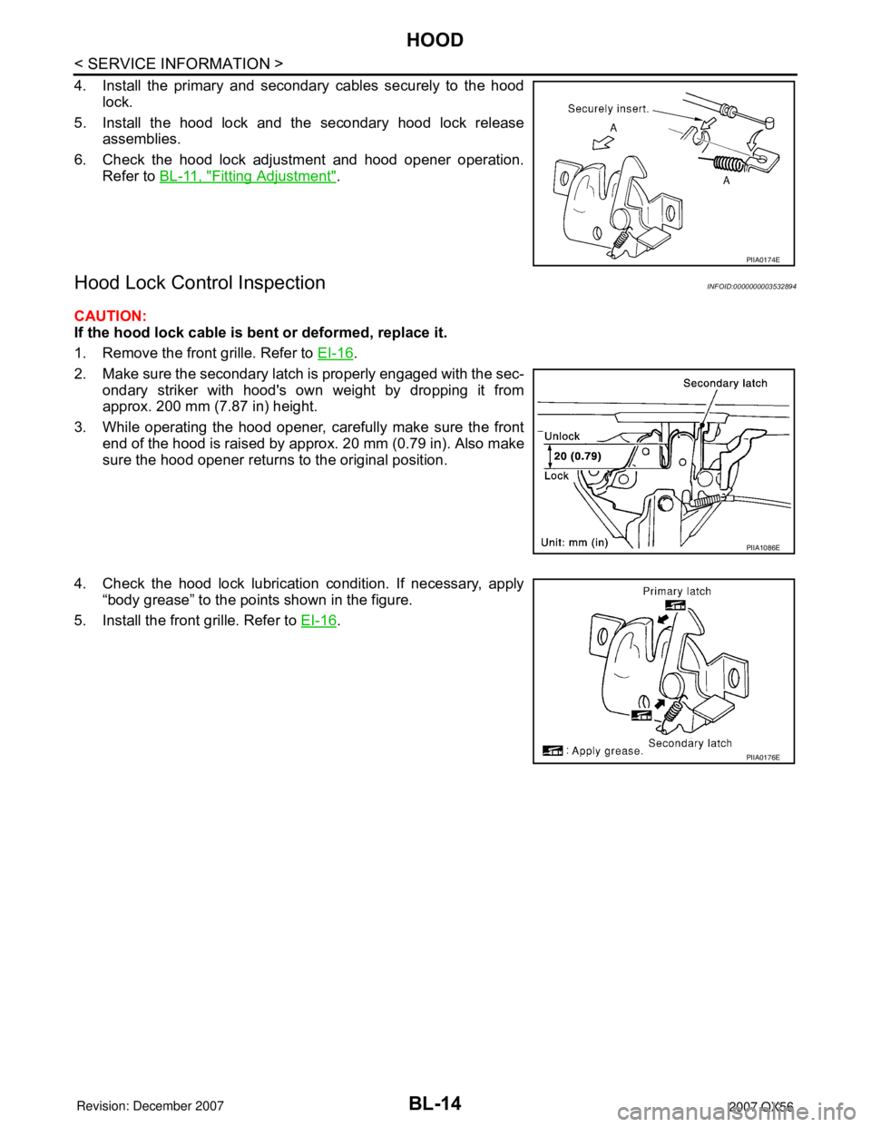
4. Install the primary and secondary cables securely to the hood
lock.
5. Install the hood lock and the secondary hood lock release
assemblies.
6. Check the hood lock adjustment and hood opener operation.
Refer to BL-11, "
Fitting Adjustment".
Hood Lock Control InspectionINFOID:0000000003532894
CAUTION:
If the hood lock cable is bent or deformed, replace it.
1. Remove the front grille. Refer to EI-16
.
2. Make sure the secondary latch is properly engaged with the sec-
ondary striker with hood's own weight by dropping it from
approx. 200 mm (7.87 in) height.
3. While operating the hood opener, carefully make sure the front
end of the hood is raised by approx. 20 mm (0.79 in). Also make
sure the hood opener returns to the original position.
4. Check the hood lock lubrication condition. If necessary, apply
“body grease” to the points shown in the figure.
5. Install the front grille. Refer to EI-16
.
PIIA0174E
PIIA1086E
PIIA0176E
Page 817 of 3061
BL-106
< SERVICE INFORMATION >
DOOR
DOOR
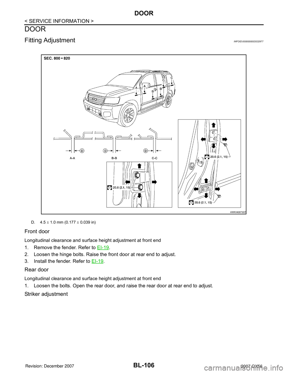
Fitting AdjustmentINFOID:0000000003532977
Front door
Longitudinal clearance and surface height adjustment at front end
1. Remove the fender. Refer to EI-19.
2. Loosen the hinge bolts. Raise the front door at rear end to adjust.
3. Install the fender. Refer to EI-19
.
Rear door
Longitudinal clearance and surface height adjustment at front end
1. Loosen the bolts. Open the rear door, and raise the rear door at rear end to adjust.
Striker adjustment
D. 4.5 ± 1.0 mm (0.177 ± 0.039 in)
AWKIA0675ZZ