cooling INFINITI QX56 2007 Factory Owner's Manual
[x] Cancel search | Manufacturer: INFINITI, Model Year: 2007, Model line: QX56, Model: INFINITI QX56 2007Pages: 3061, PDF Size: 64.56 MB
Page 470 of 3061

ATC-100
< SERVICE INFORMATION >
TROUBLE DIAGNOSIS
1. Turn ignition switch OFF.
2. Disconnect BCM connector and front air control connector.
3. Check continuity between BCM harness connector M18 terminal28 and front air control harness connector M49 terminal 10.
OK or NG
OK >> GO TO 11.
NG >> Repair harness or connector.
11 .CHECK VOLTAGE FOR FRONT AIR CONTROL (FAN ON SIGNAL)
1. Reconnect BCM connector and front air control connector.
2. Turn ignition switch ON.
3. Check voltage between front air control harness connector M49 terminal 10 and ground.
OK or NG
OK >> GO TO 12.
NG-1 >> If the voltage is approx. 5V when blower moto r is ON, replace front air control. Refer to ATC-123,
"Removal and Installation" .
NG-2 >> If the voltage is approx. 0V when blower motor is OFF, replace BCM. Refer to BCS-24, "
BCM".
12.CHECK CAN COMMUNICATION
Check CAN communication. Refer to LAN-4
.
•BCM – ECM
• ECM – IPDM E/R
• ECM – Front air control
OK or NG
OK >> Inspection End.
NG >> Repair or replace malfunctioning part(s).
Insufficient CoolingINFOID:0000000003533260
SYMPTOM: Insufficient cooling
INSPECTION FLOW
1.CONFIRM SYMPTOM BY PERFORMING OPER ATIONAL CHECK - TEMPERATURE DECREASE
1. Press the AUTO switch.
2. Turn temperature control dial (driver) counterclockwise until 16 ° C (60 ° F) is displayed.
3. Check for cold air at discharge air outlets.
Can the symptom be duplicated?
YES >> GO TO 3.
NO >> GO TO 2.
2.CHECK FOR ANY SYMPTOMS
Perform a complete operational check for any symptoms. Refer to ATC-50, "
Operational Check (Front)" .
Does another symptom exist?
28 - 10 Continuity should exist.
WJIA0450E
Te r m i n a l s
Condition Voltage
(+)
(-)
Front air con-
trol connector Te r m i n a l N o .
M49 10 Ground A/C switch: ON
Blower motor
operates
Approx. 0V
A/C switch: OFF Approx. 5V
WJIA0451E
Page 471 of 3061

TROUBLE DIAGNOSISATC-101
< SERVICE INFORMATION >
C
DE
F
G H
I
K L
M A
B
AT C
N
O P
YES >> Refer to ATC-32, "How to Perform Trouble Diagnosis for Quick and Accurate Repair" .
NO >> System OK.
3.CHECK FOR SERVICE BULLETINS
Check for any service bulletins.
>> GO TO 3.
4.PERFORM SELF-DIAGNOSIS
Perform self-diagnosis Refer to ATC-48, "
A/C System Self-Diagnosis Function" .
OK or NG
OK >> GO TO 5.
NG >> Refer to ATC-48, "
A/C System Self-Diagnosis Function" .
5.CHECK DRIVE BELTS
Check compressor belt tension. Refer to EM-13, "
Checking Drive Belts" .
OK or NG
OK >> GO TO 6.
NG >> Adjust or replace compressor belt. Refer to EM-13, "
Removal and Installation" .
6.CHECK AIR MIX DOOR OPERATION
Check and verify air mix door me chanism for smooth operation.
Does air mix door operate correctly?
YES >> GO TO 7.
NO >> Repair or replace air mix door control linkage.
7.CHECK COOLING FAN MOTOR OPERATION
Check and verify cooling fan moto r for smooth operation. Refer to EC-469, "
Description" .
Does cooling fan motor operate correctly?
YES >> GO TO 8.
NO >> Check cooling fan motor. Refer to EC-469
.
8.CHECK WATER VALVE OPERATION
Check and verify water valve for smooth operation. Refer to ATC-113, "
Water Valve Circuit".
Does water valve operate correctly?
YES >> GO TO 8.
NO >> Check water valve circuit. Refer to ATC-113, "
Water Valve Circuit" .
9.CHECK RECOVERY/RECYCLING EQUIPMENT BEFORE USAGE
Check recovery/recycling equipment befor e connecting to vehicle. Verify there is no pressure in the recovery/
recycling equipment by checking the gauges. If pressure exists, recover refrigerant from equipment lines.
>> GO TO 9.
10.CHECK REFRIGERANT PURITY
1. Connect recovery/recycling equipment to vehicle.
2. Confirm refrigerant purity in supply tank us ing recovery/recycling and refrigerant identifier.
OK or NG
OK >> GO TO 10.
NG >> Check contaminated refrigerant. Refer to AT C - 3 , "
Contaminated Refrigerant" .
11 .CHECK FOR EVAPORATOR FREEZE UP
Start engine and run A/C. Check for evaporator freeze up.
Does evaporator freeze up?
YES >> Perform performance test diagnoses. Refer to "PERFORMANCE TEST DIAGNOSES" .
NO >> GO TO 11.
Page 476 of 3061

ATC-106
< SERVICE INFORMATION >
TROUBLE DIAGNOSIS
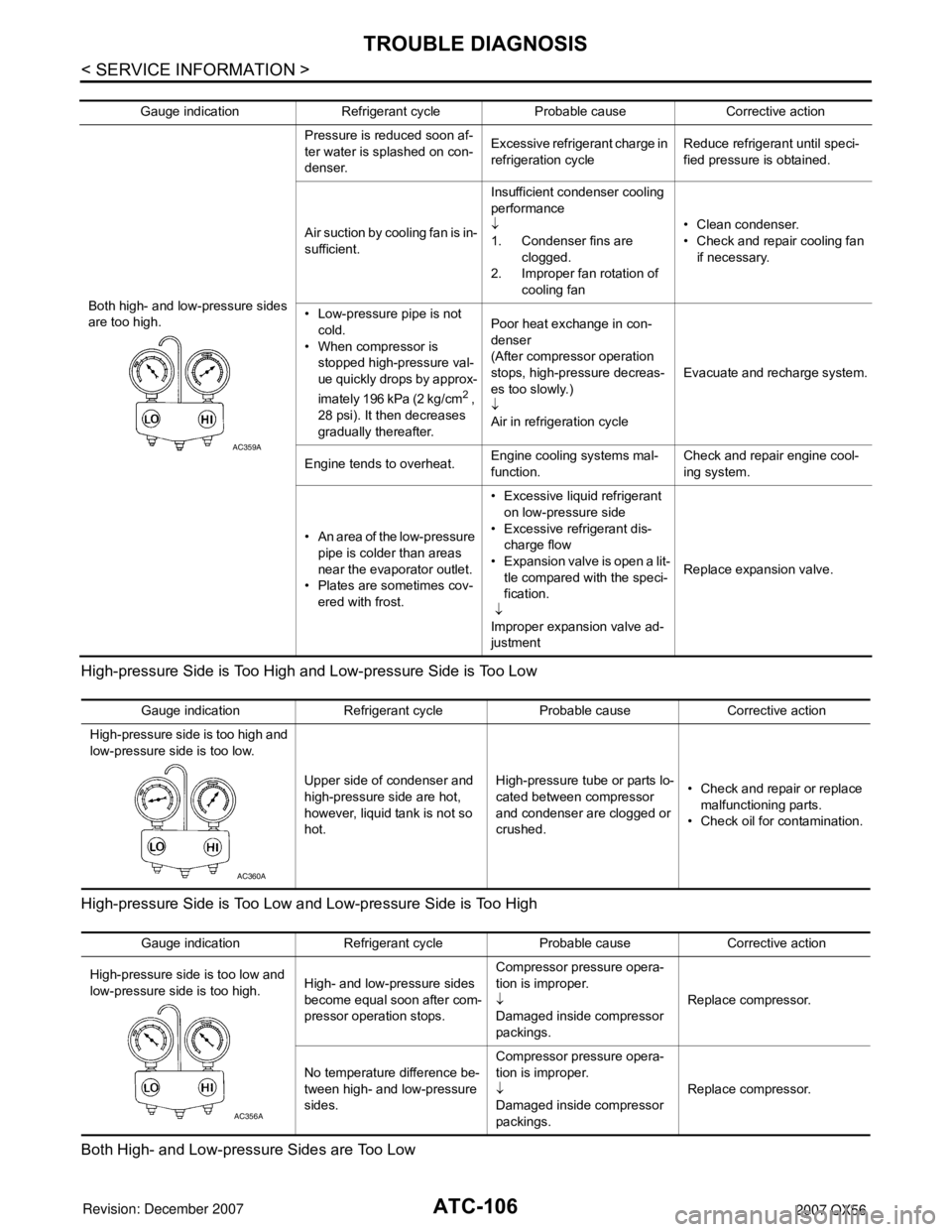
High-pressure Side is Too High and Low-pressure Side is Too Low
High-pressure Side is Too Low and Low-pressure Side is Too High
Both High- and Low-pressure Sides are Too Low
Gauge indication Refrigerant cycle Probable cause Corrective action
Both high- and low-pressure sides
are too high. Pressure is reduced soon af-
ter water is splashed on con-
denser.
Excessive refrigerant charge in
refrigeration cycle
Reduce refrigerant until speci-
fied pressure is obtained.
Air suction by cooling fan is in-
sufficient. Insufficient condenser cooling
performance
↓
1. Condenser fins are
clogged.
2. Improper fan rotation of cooling fan • Clean condenser.
• Check and repair cooling fan
if necessary.
• Low-pressure pipe is not cold.
• When compressor is stopped high-pressure val-
ue quickly drops by approx-
imately 196 kPa (2 kg/cm
2 ,
28 psi). It then decreases
gradually thereafter. Poor heat exchange in con-
denser
(After compressor operation
stops, high-pressure decreas-
es too slowly.)
↓
Air in refrigeration cycle
Evacuate and recharge system.
Engine tends to overheat. Engine cooling systems mal-
function. Check and repair engine cool-
ing system.
• An area of the low-pressure pipe is colder than areas
near the evaporator outlet.
• Plates are sometimes cov- ered with frost. • Excessive liquid refrigerant
on low-pressure side
• Excessive refrigerant dis- charge flow
• Expansion valve is open a lit- tle compared with the speci-
fication.
↓
Improper expansion valve ad-
justment Replace expansion valve.
AC359A
Gauge indication Refrigerant cycle Probable cause Corrective action
High-pressure side is too high and
low-pressure side is too low.
Upper side of condenser and
high-pressure side are hot,
however, liquid tank is not so
hot.High-pressure tu
be or parts lo-
cated between compressor
and condenser are clogged or
crushed. • Check and repair or replace
malfunctioning parts.
• Check oil for contamination.
AC360A
Gauge indication Refrigerant cycle Probable cause Corrective action
High-pressure side is too low and
low-pressure side is too high. High- and low-pressure sides
become equal soon after com-
pressor operation stops.Compressor pressure opera-
tion is improper.
↓
Damaged inside compressor
packings.
Replace compressor.
No temperature difference be-
tween high- and low-pressure
sides. Compressor pressure opera-
tion is improper.
↓
Damaged inside compressor
packings.
Replace compressor.
AC356A
Page 478 of 3061

ATC-108
< SERVICE INFORMATION >
TROUBLE DIAGNOSIS
Insufficient Heating
INFOID:0000000003533261
SYMPTOM: Insufficient heating
INSPECTION FLOW
1.CONFIRM SYMPTOM BY PERFORMING OPER ATIONAL CHECK - TEMPERATURE INCREASE
1. Press the AUTO switch.
2. Turn the temperature control dial (driver) clockwise until 32 ° C (90 ° F) is displayed.
3. Check for hot air at discharge air outlets.
Can this symptom be duplicated?
YES >> GO TO 2.
NO >> Perform complete system operational check. Refer to ATC-50, "
Operational Check (Front)" .
2.CHECK FOR SERVICE BULLETINS
Check for any service bulletins.
>> GO TO 3.
3.PERFORM SELF-DIAGNOSIS
Perform self-diagnosis. Refer to ATC-48, "
A/C System Self-Diagnosis Function" .
OK or NG
OK >> GO TO 4.
NG >> Refer to ATC-48, "
A/C System Self-Diagnosis Function" .
4.CHECK ENGINE COOLING SYSTEM
1. Check for proper engine coolant level. Refer to CO-9, "
Inspection".
2. Check hoses for leaks or kinks.
3. Check radiator cap. Refer to CO-9, "
Inspection" .
4. Check for air in cooling system.
>> GO TO 5.
5.CHECK AIR MIX DOOR OPERATION
Check the operation of the air mix door.
OK or NG
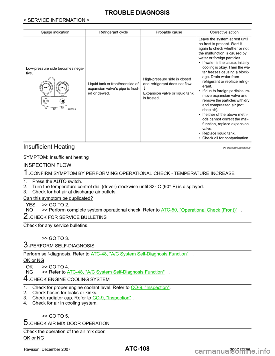
Gauge indication Refrigerant cycle Probable cause Corrective action
Low-pressure side becomes nega-
tive. Liquid tank or front/rear side of
expansion valve′s pipe is frost-
ed or dewed. High-pressure side is closed
and refrigerant does not flow.
↓
Expansion valve or liquid tank
is frosted. Leave the system at rest until
no frost is present. Start it
again to check whether or not
the malfunction is caused by
water or foreign particles.
• If water is the cause, initially
cooling is okay. Then the wa-
ter freezes causing a block-
age. Drain water from
refrigerant or replace refrig-
erant.
• If due to foreign particles, re-
move expansion valve and
remove the particles with dry
and compressed air (not
shop air).
• If either of the above meth- ods cannot correct the mal-
function, replace expansion
valve.
• Replace liquid tank.
• Check oil for contamination.
AC362A
Page 483 of 3061

TROUBLE DIAGNOSISATC-113
< SERVICE INFORMATION >
C
DE
F
G H
I
K L
M A
B
AT C
N
O P
Does another symptom exist?
YES >> Refer to ATC-32, "How to Perform Trouble Diagnosis for Quick and Accurate Repair".
NO >> Replace front air control. Refer to ATC-123, "
Removal and Installation".
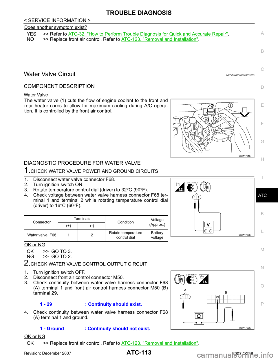
Water Valve CircuitINFOID:0000000003533265
COMPONENT DESCRIPTION
Water Valve
The water valve (1) cuts the flow of engine coolant to the front and
rear heater cores to allow for maximum cooling during A/C opera-
tion. It is controlled by the front air control.
DIAGNOSTIC PROCEDURE FOR WATER VALVE
1.CHECK WATER VALVE POWER AND GROUND CIRCUITS
1. Disconnect water valve connector F68.
2. Turn ignition switch ON.
3. Rotate temperature control dial (driver) to 32 °C (90 °F).
4. Check voltage between water valve harness connector F68 ter- minal 1 and terminal 2 while rotating temperature control dial
(driver) to 16 °C (60 °F).
OK or NG
OK >> GO TO 3.
NG >> GO TO 2.
2.CHECK WATER VALVE CONTROL OUTPUT CIRCUIT
1. Turn ignition switch OFF.
2. Disconnect front air control connector M50.
3. Check continuity between water valve harness connector F68 (A) terminal 1 and front air control harness connector M50 (B)
terminal 29.
4. Check continuity between water valve harness connector F68 (A) terminal 1 and ground.
OK or NG
OK >> Replace front air control. Refer to ATC-123, "Removal and Installation".
WJIA1791E
ConnectorTe r m i n a l s
Condition Voltage
(Approx.)
(+) (-)
Water valve: F68 1 2 Rotate temperature
control dial Battery
voltage
WJIA1792E
1 - 29 : Continuity should exist.
1 - Ground : Continuity should not exist.
WJIA1793E
Page 491 of 3061

TROUBLE DIAGNOSISATC-121
< SERVICE INFORMATION >
C
DE
F
G H
I
K L
M A
B
AT C
N
O P
The intake sensor is located on the heater & cooling unit. It converts
temperature of air after it passes through the evaporator into a resis-
tance value which is then input to the front air control.
DIAGNOSTIC PROCEDURE FOR INTAKE SENSOR
SYMPTOM: Intake sensor circuit is open or shorted. Using the CON-
SULT-II, DTC B2581 or B2582 is di splayed. Without a CONSULT-II,
code 56 or 57 is indicated on front air control as a result of conduct-
ing the front air control self-diagnosis.
1.CHECK VOLTAGE BETWEEN INTAKE SENSOR AND GROUND
1. Disconnect intake sensor connector.
2. Turn ignition switch ON.
3. Check voltage between intake sensor harness connector M146 terminal 2 and ground.
OK or NG
OK >> GO TO 2.
NG >> GO TO 4.
2.CHECK CIRCUIT CONTINUITY BETWEEN IN TAKE SENSOR AND FRONT AIR CONTROL
1. Turn ignition switch OFF.
2. Disconnect front air control connector.
3. Check continuity between intake sensor harness connector M146 terminal 1 and front air control harness connector M49 ter-
minal 21.
OK or NG
OK >> GO TO 3.
NG >> Repair harness or connector.
3.CHECK INTAKE SENSOR
Refer to "Intake Sensor Circuit".
OK or NG
OK >> 1. Replace front air control. Refer to ATC-123, "Removal and Installation"
2. Go to ATC-48, "A/C System Self-Diagnosis Function" and perform self-diagnosis.
NG >> 1. Replace intake sensor. Refer to ATC-127
.
2. Go to ATC-48, "
A/C System Self-Diagnosis Function" and perform self-diagnosis.
WJIA0571E
WJIA0464E
2 - Ground : Approx. 5V
WJIA1375E
1 - 21 : Continuity should exist.
WJIA1376E
Page 497 of 3061

INTAKE SENSORATC-127
< SERVICE INFORMATION >
C
DE
F
G H
I
K L
M A
B
AT C
N
O P
INTAKE SENSOR
Removal and InstallationINFOID:0000000003533274
REMOVAL
1. Remove the glove box . Refer to IP-10, "Removal and Installation".
2. Disconnect the intake sensor electrical connector. NOTE:
The intake sensor is located on the top of the front heater and
cooling unit assembly next to the A/C evaporator cover.
3. Twist the intake sensor to remove the intake sensor from the front heater and cooling unit assembly.
INSTALLATION
Installation is in the reverse order of removal.
LJIA0133E
Page 498 of 3061

ATC-128
< SERVICE INFORMATION >
BLOWER MOTOR
BLOWER MOTOR
ComponentINFOID:0000000003533275
Front Blower MotorRear Blower Motor
Removal and InstallationINFOID:0000000003533276
FRONT BLOWER MOTOR
Removal
1. Remove the glove box assembly. Refer to IP-10, "Removal and Installation".
2. Disconnect the front blower motor electrical connector.
3. Remove the three screws and remove the front blower motor.
Installation
Installation is in the reverse order of removal.
LJIA0136E
1. Front heater and cooling unit assembly 2. Front blower motor 3. Variable blower control
LJIA0055E
1. Rear blower motor 2. Rear blower motor case 3. Rear blower motor resistor
Page 500 of 3061

ATC-130
< SERVICE INFORMATION >
IN-CABIN MICROFILTER
IN-CABIN MICROFILTER
Removal and InstallationINFOID:0000000003533277
FUNCTION
The air inside the passenger compartment is filtered by the in-cabin
microfilters when the heater or A/C controls are set on either the
recirculation or fresh mode. The two in-cabin microfilters are located
in the front heater and cooling unit assembly. The rear heater and
cooling unit assembly only draws in air from the passenger compart-
ment to recirculate into the passenger compartment, so the rear
heater and cooling unit assembly is not equipped with in-cabin
microfilters.
REPLACEMENT TIMING
Replacement of the two in-cabin microfilters is recommended on a regular interval depending on the driving
conditions. Refer to MA-6
. It may also be necessary to replace the tw o in-cabin microfilters as part of a compo-
nent replacement if the in-cabin microfilters are damaged.
REPLACEMENT PROCEDURE
1. Remove the two lower glove box hinge pins to remove the glove box from the instrument panel and let it hang from the cord.
2. Remove the screw and remove the in-cabin microfilter cover.
3. Remove the in-cabin microfilters from the front heater and cool- ing unit assembly housing.
4. Insert the first new in-cabin micr ofilter into the front heater and
cooling unit assembly housing and slide it over to the right.
Insert the second new in-cabin mi crofilter into the front heater
and cooling unit assembly housing.
NOTE:
The in-cabin microfilters are marked with air flow arrows. The
end of the microfilter with the arro w should face the rear of the
vehicle. The arrows should point downward.
LJIA0012E
WLIA0027E
LJIA0134E
LJIA0148E
Page 502 of 3061

ATC-132
< SERVICE INFORMATION >
HEATER & COOLING UNIT ASSEMBLY
HEATER & COOLING UNIT ASSEMBLY
ComponentINFOID:0000000003533278
Front Heater and Cooling Unit Assembly
AWJIA0319ZZ
1. High-pressure A/C pipe 2. Front expansion valve 3. Low-pressure A/C pipe
4. Front heater core pipe 5. Front heater core hose 6. A/C drain hose
7. Front heater and cooling unit assembly